Determining the suitability of radio components is the main procedure carried out when repairing or servicing electronic equipment. And if everything is more or less clear with passive elements, then active ones require special approaches. It is not difficult to check the resistance of a resistor or the integrity of an inductor.
With active ingredients the situation is a little more complicated. It is necessary to separately understand how to check a diode with a multimeter with your own hands, given that this is the simplest and most common semiconductor element of electronic circuits.
Checking a Diode with a Digital Multimeter
To determine the health of the diode, you can use the following method for checking it with a digital multimeter.
But first, let's remember what a semiconductor diode is.
A semiconductor diode is an electronic device that has the property of unidirectional conductivity.
The diode has two terminals. One is called the cathode, which is negative. The other output is the anode. It is positive.
At the physical level, the diode is a single pn junction.
Let me remind you that semiconductor devices can have several pn junctions. For example, the dinistor has three of them! A semiconductor diode is essentially the simplest electronic device based on just one pn junction.
Let us remember that the operating properties of the diode appear only when connected directly. What does direct connection mean? This means that a positive voltage (+) is applied to the anode terminal, and a negative voltage is applied to the cathode, i.e. ( — ). current begins to flow through its pn junction .
When turned on in reverse, when a negative voltage ( - ) is applied to the anode and a positive voltage (+) is applied to the cathode, the diode is closed and does not allow current to pass through .
This will continue until the voltage on the reverse-connected diode reaches a critical value, after which damage to the semiconductor crystal occurs. This is the main property of the diode - one-way conductivity.
The vast majority of modern digital multimeters (testers) have the ability to test a diode in their functionality. This function can also be used to test bipolar transistors. It is indicated in the form of a diode symbol next to the marking of the multimeter mode switch.
A little note! It is worth understanding that when checking diodes in direct connection, the display does not show the transition resistance, as many people think, but its threshold voltage ! It is also called the voltage drop across the pn junction . This is the voltage above which the pn junction opens completely and begins to pass current. If we draw an analogy, this is the amount of effort aimed at opening the “door” for electrons. This voltage ranges from 100 to 1000 millivolts (mV). This is what the device display shows.
In reverse connection, when the negative ( - ) terminal of the tester is connected to the anode, and the positive (+) terminal is connected to the cathode, then no values should be shown on the display. This indicates that the junction is working properly and does not allow current to flow in the opposite direction.
In the documentation (datasheets) for imported diodes, the threshold voltage is referred to as Forward Voltage Drop (abbreviated Vf ), which literally translates as “ voltage drop in direct connection .”
The voltage drop across the pn junction itself is undesirable. If we multiply the current flowing through the diode (direct current) by the magnitude of the voltage drop, then we get nothing more than power dissipation - the power that is uselessly spent on heating the element.
You can find out more about the diode parameters here.
Diode check.
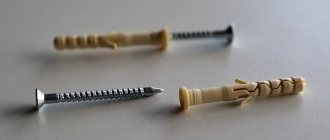
To make it more clear, let’s check the 1N5819 rectifier diode. This is a Schottky diode. We will soon see this.
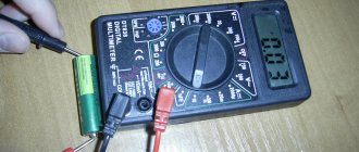
We will perform the test using the Victor VC9805+ multitester. Also, for convenience, a solderless breadboard is used.
I draw your attention to the fact that during measurements you cannot hold the leads of the element being tested and the metal probes with both hands. This is a big mistake. In this case, we measure not only the parameters of the diode, but also the resistance of our body. This can significantly affect the result of the test.
You can hold the probes and terminals of the element with only one hand! In this case, only the measuring device itself and the element being tested are included in the measuring circuit. This recommendation is also valid when measuring the resistance of resistors, as well as when checking capacitors. Don't forget this important rule!
So, let's check the diode in direct connection. In this case, we connect the positive probe (red) of the multimeter to the anode of the diode. the negative probe ( black ) to the cathode. In the photo shown earlier, you can see that the cylindrical body of the diode has a white ring on one edge. It is on this side that it has a cathode terminal. This is how the cathode terminal of most imported diodes is marked.
As you can see, the threshold voltage value for 1N5819 appeared on the display of the digital multimeter. Since this is a Schottky diode, its value is small - only 207 millivolts (mV).
Now let's check the diode in reverse connection. We remind you that when switched in reverse, the diode does not allow current to pass through. Looking ahead, we note that in the reverse connection, a small current still flows through the pn junction. This is the so-called reverse current ( Irev ). But it is so small that it is usually not taken into account.
Let's change the connection of the diode to the multimeter's test leads. We connect the red probe to the cathode, and the black probe to the anode.
The display will show “ 1 ” in the most significant digit of the display. This indicates that the diode does not pass current and its resistance is high. Thus, we checked the 1N5819 diode and it turned out to be fully functional.
Many people ask the question: “Is it possible to test a diode without desoldering it from the board?” Yes, you can. But in this case, it is necessary to remove at least one of its pins from the board. This must be done in order to exclude the influence of other parts that are connected to the diode being tested.
If this is not done, then the measuring current will flow through everything, including through the elements connected to it. As a result of testing, the multimeter readings will be incorrect!
In some cases, this rule can be neglected, for example, when it is clearly visible that there are no parts on the printed circuit board that could affect the test result.
Application of the tester
The simplest, but no less effective, device for testing elements of electronic circuits, semiconductor diodes, including, is a radio component tester.
Moreover, this instrument is the most common among radio technicians due to its unpretentiousness, small weight and size parameters and the ability to measure almost any characteristics of radio elements and circuits important for repairs.
It is believed that digital multimeters, due to their accuracy and ease of use, are gradually replacing analog ones. However, you shouldn’t compromise on the accuracy of the old “tseshka”.
It already includes microcircuits, and bridge resistors have an error of 1-2% (this is very high accuracy even for integrated circuits). Therefore, to check the serviceability of a diode or transistor, there is no need to buy a new multimeter, if you have an analog one.
Digital display has taken root due to the lack of mechanical components in the multimeter. This increased its impact resistance and service life.
Checking diodes has been simplified with the advent of a sound signal, which allows you not even to pay attention to the display. Most multimeters have a special mode that allows you to literally and figuratively ring the diode. It is marked on the body with the corresponding sign.
Just insert the black plug into the COM connector, and the red plug into the resistance measurement connector (Ω), set the switch to diode testing mode, and you can start testing.
Classification
Diodes are simple semiconductor radioelements based on a pn junction. The figure shows a graphical representation of the most common types of these devices. Anode o, cathode - “-” (given for clarity; in the diagrams, a graphic designation is sufficient to determine the polarity).
Accepted notations
Types of diodes shown in the figure:
- A – rectifying;
- B – zener diode;
- C – varicap;
- D – microwave diode (high voltage);
- E – reversed diode;
- F – tunnel;
- G – LED;
- H – photodiode.
Now let's look at verification methods for each of the listed types.
How many volts does the forward voltage of an LED have?
Current-voltage characteristic of LED.
If you study the standard current-voltage characteristic of an LED, you will notice several characteristic points on it:
- At point 1 pn the junction begins to open. Current begins to flow through it and the LED begins to glow.
- As the voltage increases, the current reaches the operating value (in this case 20 mA), and at point 2 the voltage is operating for this LED, the brightness becomes optimal.
- With a further increase in voltage, the current increases and at point 3 reaches its maximum permissible value. After this, it quickly fails, and the current-voltage characteristic curve grows only theoretically (dashed section).
It should be noted that after the end of the bend and reaching the linear section, the current-voltage characteristic has a large steepness, which leads to two consequences:
- when the current increases (for example, if the driver is faulty or there is no ballast resistor), the voltage increases slightly, so we can talk about a constant voltage drop across the pn junction, regardless of the operating current (stabilization effect);
- With a small increase in voltage, the current increases quickly.
Therefore, it is impossible to noticeably increase the voltage on the element relative to the working one.
Checking the rectifier diode and zener diode
The protective diode, as well as the rectifier diode (including the power diode) or Schottky diode, can be checked using a multimeter (or use an ohmmeter); to do this, we switch the device to the continuity mode as shown in the photo.
Multimeter mode in which semiconductor rectifier diodes are tested
We connect the probes of the measuring device to the terminals of the radio element. By connecting the red wire (“+”) to the anode and the black (“-”) wire to the cathode, the multimeter (or ohmmeter) display will display the threshold voltage value of the diode being tested. After we change the polarity, the device should show infinitely high resistance. In this case, we can state that the element is in good condition.
If, when connecting back, the multimeter registers a leak, it means that the radio element has “burnt out” and needs to be replaced.
Note that this testing technique can be used to test diodes on a car generator.
Zener diode testing is carried out according to a similar principle, however, such a test does not allow one to determine whether the voltage is stabilized at a given level. Therefore, we need to assemble a simple circuit.
Testing using a regulated power supply
Designations:
- PSU – adjustable power supply (displaying load current and voltage);
- R – current-limiting resistance;
- VT – Zener diode or avalanche diode under test.
The verification principle is as follows:
- we assemble the circuit;
- set the multimeter mode, which allows you to measure DC voltage up to 200 V;
Selecting the required mode for testing
- turn on the power supply and begin to gradually increase the voltage until the ammeter on the power supply shows that current is flowing through the circuit;
- connect the multimeter as shown in the figure and measure the stabilization voltage.
How to check LED strip for performance
On our website there is a whole article on how to check an LED strip; here we will look at express testing methods.
I’ll say right away that it won’t be possible to illuminate it entirely with a multimeter; in some situations, only a slight glow is possible in Hfe mode. Firstly, you can check each diode individually, in the diode test mode.
Secondly, sometimes it is not the diodes that burn out, but the current-carrying parts. To check this, you need to put the tester into continuity mode and touch each power terminal at different ends of the area being tested. This way you will identify the intact part of the tape and the damaged one.
The red and blue lines highlight the stripes that should ring from the very beginning to the end of the LED strip.
How to test an LED strip with a battery? The power supply for the tape is 12 Volts. You can use a car battery, but it is large and not always available. Therefore, a 12V battery will come to the rescue. Used in radio doorbells and control panels. It can be used as a power source when testing problematic areas of the LED strip.
Varicap testing
Unlike conventional diodes, the pn junction of varicaps has a variable capacitance, the value of which is proportional to the reverse voltage. Checking for open or short circuits for these elements is carried out in the same way as for conventional diodes. To check the capacity, you will need a multimeter that has a similar function.
Demonstration of checking varicap
To test, you will need to set the multimeter to the appropriate mode, as shown in photo (A) and insert the part into the connector for capacitors.
As one of the commentators on this article correctly noted, it is indeed impossible to determine the capacitance of a varicap without using the rated voltage. Therefore, if there is a problem with identification by appearance, you will need to assemble a simple attachment for a multimeter (I repeat for critics, a digital multimeter with the function of measuring the capacitance of capacitors, for example UT151B).
Multimeter attachment for measuring varicap capacity
Designations:
- Resistors: R1, R2 -120 kOhm (yes, two resistors, yes in series, no, one cannot be replaced, parasitic capacitance, no further comment); R3 – 47 kOhm; R4 – 100 Ohm.
- Capacitors: C1 – 0.15 µF; C2 – 75 pF; C3 – 6…30 pF; C4 - 47 uF ha 50 volts.
The device requires configuration. It is quite simple, the assembled device is connected to a measuring device (a multimeter with a capacitance measurement function). Power must be supplied from a stabilized power source (important) with a voltage of 9 volts (for example, a Krona battery). By changing the capacitance of the substring capacitor (C2), we achieve a reading on the indicator of 100 pF. We will subtract this value from the device reading.
This option is not ideal, the need for its practical use is questionable, but the circuit clearly demonstrates the dependence of the varicap capacity on the rated voltage.
How many volts are LEDs?
The parameters of LEDs mostly depend on the material from which the pn junction is made, although some of the characteristics still depend on the design. Typical values of operating voltage and glow color for low-power elements at a current of 20 mA are summarized in the table:
| Material | Glow color | Direct voltage range, V |
| GaAs, GaAlAs | Infrared | 1,1 – 1,6 |
| GaAsP, GaP, AlInGaP | Red | 1,5 – 2,6 |
| GaAsP, GaP, AlInGaP | Orange | 1,7 – 2,8 |
| GaAsP, GaP, AlInGaP | Yellow | 1,7 – 2,5 |
| GaP, InGaN | Green | 1,7 – 4 |
| ZnSe, InGaN | Blue | 3,2 – 4,5 |
| Phosphor | White | 2,7 – 4,3 |
Powerful lighting LEDs operate at high currents. Thus, the crystal of the popular LED 5730 is designed for long-term operation at a current of 150 mA. But due to the steep current-voltage characteristic, which stabilizes the voltage drop, its Urab is about 3.2 V, which fits into the value indicated in the table.
High Voltage Diode Testing
It will not be possible to check the high-voltage diode of a microwave oven in the same way as a regular one, due to its features. To test this element, you will need to assemble a circuit (shown in the figure below) connected to a 40-45 volt power supply.
Circuit for testing a diode used in a microwave oven
A voltage of 40-45 volts will be enough to test most elements of this type; the testing methodology is the same as for conventional diodes. The resistance value R should be in the range from 2 kOhm to 3.6 kOhm.
How to determine LED voltage
The most obvious method for determining the voltage of a semiconductor device is to use a regulated power supply. If the power supply is regulated from scratch and the current can be controlled (or better yet, limited), then nothing else is needed.
It is necessary to connect the LED to the source, strictly observing the polarity. Then you need to gradually increase the voltage (up to 3..3.5 V). At a certain voltage, the LED will flash at full power. This level will approximately correspond to the operating current, which can be read by an ammeter. If the device does not have a built-in ammeter, then it is highly advisable to monitor the current using an external device.
Testing an LED using a regulated power supply.
This method is applicable to optical devices. The glow of UV and IR LEDs is not visible to human vision, but in the latter case, you can observe the LED turning on through the smartphone camera. Using this method, you can track the appearance of infrared radiation.
The glow of the IR LED is not visible to the naked eye, but is observed through the smartphone camera.
Important! When increasing the voltage, do not exceed the limit of 3..3.5 V! If the LED does not light up under such conditions, the polarity of the device connection may be incorrect. It may fail due to the reverse voltage limit being exceeded.
If there is no regulated source, you can take a regular power supply with a fixed output, which is obviously higher than the expected LED voltage. Or even a 9 V battery, but in this case you can only test a low power LED. A resistor must be soldered in series to the light-emitting element so that the current in the circuit does not exceed the upper limit. If the LED is assumed to be low-power and operates at a current of no more than 20 mA, then for a source with an output voltage of 12 V, the resistor should be about 500 Ohms. If you are using a powerful lighting device (for example, size 5730) with a current of 150 mA (a battery will not always provide such a current), then the resistor should be about 10 ohms. You need to connect the chain to a constant voltage source, make sure the LED lights up and measure the voltage drop across it.
LED with a soldered resistor.
There are alternative ways to find out how many volts an LED is rated for.
Multimeter
Correct polarity of LED connection to the tester.
On some multimeters, the voltage applied to the terminals in diode test mode is high enough to light the LED. Such a meter can be used to determine the operating voltage of an LED while simultaneously checking the pinout of the semiconductor element. If the pn junction is connected correctly, it will light up, and the tester will show some resistance (depending on the type of LED). The problem with this method is that a second multimeter is required to measure the actual value of Uoperating at the LED terminals. And another point: the measuring voltage of the multimeter is unlikely to be sufficient to bring the LED to the current operating point. Visually this is noticeable by the insufficiently bright glow, but for measurements this will mean that the LED has not reached the linear part of the current-voltage characteristic and the actual value of the operating voltage will be higher.
Checking the LED for serviceability
By appearance
Signal LEDs of various colors.
The operating voltage can be approximately estimated by the appearance and color of the LED (sometimes the color can be determined even without supplying power to the device). To do this, you can use the table above. But it is not possible to unambiguously determine the voltage by the color of the LED. Often, manufacturers tint the compound so that the color of the pn junction radiation matches the color of the lens and produces a new shade. In addition, even within the same color there is a spread of parameters (see table) for LEDs of different types. So, for a white LED, the voltage difference can reach more than 50%.
Tunnel and reverse diodes
Considering that the current flowing through a diode depends on the voltage applied to it, testing consists of analyzing this dependence. To do this, you will need to assemble a circuit, for example, such as shown in the figure.
Testing tunnel type diodes
List of elements:
- VD – tunnel type diode under test;
- Up – any galvanic power source with a discharge current of about 50 mA;
- Resistances: R1 – 12Ω, R2 – 22Ω, R3 – 600Ω.
The measurement range set on the multimeter should not be less than the maximum current of the diode; this parameter is indicated in the datasheet of the radio element.
Video: Example of checking a diode with a multimeter
Testing algorithm:
- the maximum value is set on variable resistor R3;
- the element under test is connected, observing the polarity indicated on the diagram;
- By decreasing the value of R3, we observe the readings of the measuring device.
If the element is working properly, during the measurement process the device will show an increase in current up to Imax of the diode, followed by a sharp decrease in this value. With a further increase in voltage, the current will decrease to Imin, after which it will begin to increase again.
Checking the LED with a battery
To test the LED using a battery, you need to assemble the circuit according to the diagram.
Diagram for checking LED1 from a 9V battery.
On the diagram:
- LED1 – device being tested.
- 9V – power source (battery with a voltage of 9V).
- VAΩ is a measuring device for measuring V – voltage, A – current, Ω – resistance, AVOmeter or multimeter. In the diagram it works in voltage measurement mode.
- R1 is a current limiting resistor.
- R2 is a variable resistor that sets the brightness of the LED.
Resistor R2 on the multimeter sets the rated operating current. A working LED element produces light. Faulty - no light.
The term “multimeter” is a transliteration of the international name “Multimeter”. Derived from the terms Multi – many and meter – to measure. It has the names “tester”, “AVOmeter” - from Ampere-Volt-Ohmmeter.
A modern multimeter is a universal measuring device with a digital display.
One of the types of multimeters.
Another name for the device is “tester” - a Cyrillic transliteration of the international term tester - tester, verifier, tester.
LED testing
Testing LEDs is practically no different from testing rectifier diodes. How to do this was described above. We check the LED strip (more precisely, its SMD elements), infrared LED, and also laser LED using the same method.
Unfortunately, a powerful radio element of this group, which has a higher operating voltage, cannot be tested using the indicated method. In this case, you will additionally need a stabilized power source. The testing algorithm is as follows:
- We assemble the circuit as shown in the figure. The power supplies are set to the operating voltage of the LED (indicated in the datasheet). The measuring range on the multimeter should be up to 10 A. Note that you can use the charger as a power supply, but then you need to add a current-limiting resistor;
Measuring the rated current on an LED
- measure the rated current and turn off the power supply;
- set the multimeter mode, which allows you to measure DC voltage up to 20 V, and connect the device in parallel to the element under test;
- turn on the power supply and remove the operating voltage parameters;
- We compare the data obtained with those indicated in the datasheet, and based on this analysis we determine the performance of the LED.
Infrared LEDs
Surely every person in the apartment has at least one remote control. Sooner or later, the day comes when the remote control stops performing its functions (signal transmission to the photodetector). After checking the batteries, the most likely cause of damage is a faulty LED.
You can test the infrared LED as follows. Turn the remote control LED towards the camera. Any gadget with a camera is suitable for this. Infrared radiation cannot be seen, but when using these devices the situation will change radically. If the LED is working, a short-term violet glow will appear on the screen.
Infrared LED glow
Another LED tester, the main element of which is an infrared photodiode - an oscilloscope. When infrared radiation hits the surface of a photocell, a voltage is created at its output. To check the LED, it must be connected to the open input of the oscilloscope. Then its radiation should be directed to the sensitive zone of the photodiode.
A working LED will show pulses on the oscilloscope monitor.
Checking the photodiode
In a simple test, the reverse and forward resistance of a radio element placed under a light source is measured, after which it is darkened and the procedure is repeated. For more accurate testing, you will need to take the current-voltage characteristic; this can be done using a simple circuit.
An example of a circuit for measuring current-voltage characteristics
To illuminate the photodiode during testing, you can use an incandescent lamp with a power of 60 W or more as a light source or bring the radio component to a chandelier.
Photodiodes sometimes have a characteristic defect, which manifests itself in the form of a chaotic change in current. To detect such a malfunction, it is necessary to connect the element under test as shown in the figure and measure the reverse current for a couple of minutes.
Testing for "creep"
If during testing the current level remains unchanged, then the photodiode can be considered working.
Testing without desoldering.
As practice shows, it is not always possible to test a diode without desoldering it when it is on the board, like other radio components (for example, a transistor, capacitor, thyristor, etc.). This is due to the fact that elements in the circuit may produce an error. Therefore, before checking the diode, it must be desoldered.
Today we can’t live without electronics. It is an integral part of any modern device or gadget. At the same time, all devices, sadly, cannot work forever and periodically break down. One of the fairly common causes of failure of a number of electrical appliances is the failure of an electrical element such as a diode.
You can check the serviceability of this component yourself at home. This article will tell you how to test a diode with a multimeter, as well as what these elements are and what the measuring device itself is.
Advantages and disadvantages
When working with devices that include a Schottky diode, you should consider their positive and negative aspects. If you connect it as an element of an electrical circuit, it will perfectly hold the current, preventing large losses.
In addition, the metal barrier has minimal capacity. This significantly increases the wear resistance and service life of the diode itself. The voltage drop when using it is minimal, and the action occurs very quickly - you just need to make a connection.
However, the large percentage of reverse current is an obvious disadvantage. Since many electrical appliances are highly sensitive, there are often cases when a slight excess of the indicator, just a couple of A, can damage the device for a long time. Also, if you carelessly check the semiconductor voltage, the diode itself may leak.
Diode diode discord
A standard diode is a component of the electrical network and acts as a pn junction semiconductor. Its structure allows current to pass through the circuit in only one direction - from the anode to the cathode (different ends of the part). To do this, you need to apply “+” to the anode and “-” to the cathode.
Note! Electric current in diodes cannot flow in the opposite direction, from the cathode to the anode.
Due to this feature of the product, if you suspect a breakdown, it can be checked with a tester or multimeter. Today there are several types of diodes in radio electronics:
Miniaturization
With the development of microelectronics, special microcircuits and single-chip microprocessors began to be widely used. All this does not exclude the use of hanging elements. However, if radioelements of conventional sizes are used for this purpose, this will negate the whole idea of miniaturization as a whole. Therefore, open-frame elements were developed - SMD components, which are 10 or more times smaller than conventional parts. The current-voltage characteristics of such components are no different from the current-voltage characteristics of conventional devices, and their reduced dimensions make it possible to use such spare parts in various microassemblies.
SMD components come in several sizes. SMD size 1206 is suitable for manual soldering. They have a size of 3.2 by 1.6 mm, which allows you to solder them yourself. Other SMD elements are more miniature, assembled at the factory with special equipment, and it is impossible to solder them yourself at home.
The operating principle of an smd component is also no different from its large counterpart, and if, for example, we consider the current-voltage characteristic of a diode, then it will be equally suitable for semiconductors of any size. The current range is from 1 to 10 amperes. The markings on the case often consist of a digital code, the decoding of which is given in special tables. They can be tested for suitability using a tester, just like their larger counterparts.
How is the check carried out?
After we have figured out the semiconductors of the electrical circuit and the purpose of the device, we can answer the question “how to check the diode for serviceability?” The whole point of checking diodes with a multimeter is their one-way electrical current carrying capacity. If this rule is observed, the electrical circuit element is considered to function correctly and without failures. Conventional diodes and Schottky diodes can be easily tested using this device. To check this semiconductor element with a multimeter, you need to do the following manipulations:
- you need to make sure that your multimeter has a diode test function;
- If such a function is available, we connect the probes of the device to the side of the semiconductor from which the “ringing” will be carried out. If this function is missing, then use the switch to switch the device to 1 kOhm. You should also select the mode for measuring resistance;
- the red wire of the measuring device must be connected to the anode end, and the black wire to the cathode end;
- after this, you need to observe changes in the forward resistance of the semiconductor;
- we draw conclusions about the presence or absence of voltage
The unit can then be switched to check for leaks or high circuits. To do this, you need to change the location of the diode output. In this state, it is also necessary to evaluate the obtained values of the device.
How to ring an LED lamp?
Any electrician has “ringed” an incandescent lamp many times, but how to check an LED lamp with a tester?
To do this, you need to remove the diffuser; it is usually glued. To separate it from the body you need a mediator, or a plastic card, it needs to be inserted between the body and the diffuser.
If you can’t do this, try warming the gluing area a little with a hairdryer.
How now to check an LED light bulb with a multimeter? In front of you will be a board with LEDs; you need to touch their terminals with the tester probes. Such SMDs light up dimly in diode testing mode (but not always). Another way to check serviceability is to test the battery with a Krona battery.
The crown produces a voltage of 9-12V, so check the diodes with short-term sliding touches to their poles. If the LED does not light up with the correct polarity, it needs to be replaced.
Checking the diode bridge
Sometimes there is a situation when you need to check the functionality of a diode bridge. It looks like an assembly consisting of four semiconductors. They are connected in such a way that the alternating voltage supplied to two of the four soldered elements becomes direct. The latter is removed from the other two terminals. As a result, the alternating voltage is rectified and converted into constant voltage.
Essentially, the principle of verification in this situation remains the same as described above. The only feature here is the determination of which output the measuring device will be connected to. There are four connection options that you should call:
- conclusions 1 – 2;
- conclusions 2 – 3;
- conclusions 1 – 4;
- conclusions 4 – 3;
By checking each output, you will get four results. The obtained indicators should be evaluated according to the same principle as for an individual semiconductor.
Difference from other semiconductors
Its main difference from other semiconductors is that the barrier is a metal element with one-way conductivity.
Such elements are made from a number of valuable metals:
- gallium arsenide;
- silicon;
- gold;
- tungsten;
- silicon carbide;
- palladium;
- platinum.
The characteristics of the desired voltage indicator and the quality of operation of the electronic device as a whole depend on which metal is chosen as the material. Silicon is most often used because of its reliability, durability and ability to operate under high power conditions. Gallium arsenide combined with arsenic or germanium is also used.
Analyzing the results
When checking diodes (regular and Schottky) with a multimeter, you will get a certain result. Now we need to understand what it could mean. Signs that indicate the health of the semiconductor include the following:
- when connecting a part of the electrical circuit to the device, the latter will output the value of the available direct voltage in this element;
Note! Different types of diodes have different voltage levels, which is why they differ. For example, for germanium products this parameter will be 0.3-0.7 volts
- when connected in the opposite way (the probe of the device to the anode of the product), zero will be recorded.
If these two indicators are met, then the semiconductor is working adequately and the cause of the failure is not in it. But if at least one of the parameters does not correspond, then the element is considered unusable and must be replaced. In addition, it should be borne in mind that it is not a breakdown, but a “leakage” that is possible. This unpleasant defect can appear during long-term use of the device or poor-quality assembly. If there is a short circuit or leakage, the resulting resistance will be quite low. Moreover, the conclusion must be made based on the type of semiconductor. For germanium elements, this indicator in this situation will range from 100 kilo-ohms to 1 mega-ohm, for silicon - thousands of mega-ohms. For rectifier semiconductors, this figure will be many times higher. As you can see, it is not so difficult to assess the performance of semiconductors in any electrical device on your own. The above principle is suitable for testing diode elements of various types and types. The main thing in this situation is to correctly connect the measuring device to the semiconductor and analyze the results obtained.
Design
The Schottky diode differs from ordinary diodes in its design, which uses a metal-semiconductor rather than a pn junction. It is clear that the properties here are different, which means the characteristics should also be different.
Indeed, a semiconductor metal has the following parameters:
- Leakage current is of great importance;
- Low voltage drop across the junction when connected directly;
- Restores charge very quickly, as it has a low value.
The Schottky diode is made of materials such as gallium arsenide, silicon; much less commonly, but can also be used, is germanium. The choice of material depends on the properties that need to be obtained, however, in any case, the maximum reverse voltage for which these semiconductors can be manufactured is not higher than 1200 volts - these are the highest voltage rectifiers. In practice, they are much more often used at lower voltages - 3, 5, 10 volts.
In the circuit diagram, the Schottky diode is designated as follows:
But sometimes you can see this designation:
This means a dual element: two diodes in one housing with a common anode or cathode, so the element has three terminals. Power supplies use such designs with a common cathode; they are convenient to use in rectifier circuits. Often the diagrams show the markings of a regular diode, but the description indicates that this is a Schottky diode, so you need to be careful.
Diode assemblies with a Schottky barrier are available in three types:
Type 1 – with a common cathode;
Type 2 – with a common anode;
Type 3 – according to the doubling scheme.
This connection helps to increase the reliability of the element: after all, being in the same housing, they have the same temperature regime, which is important if powerful rectifiers are needed, for example, 10 amperes.
But there are also disadvantages. The thing is that the low voltage drop (0.2–0.4 V) of such diodes appears at low voltages, usually 50–60 volts. At higher values they behave like regular diodes. But in terms of current, this circuit shows very good results, because it is often necessary - especially in power circuits and power modules - for the operating current of semiconductors to be at least 10A.
Another major disadvantage: for these devices, the reverse current cannot be exceeded even for an instant. They immediately fail, while silicon diodes, if their temperature has not been exceeded, restore their properties.
But there are still more positive things. In addition to the low voltage drop, the Schottky diode has a low junction capacitance value. As you know: lower capacity - higher frequency. Such a diode has found application in switching power supplies, rectifiers and other circuits with frequencies of several hundred kilohertz.
Current-voltage characteristic of the LED (volt-ampere characteristic)
The current-voltage characteristic of such a diode has an asymmetrical appearance. When a forward voltage is applied, it is clear that the current increases exponentially, and when reverse voltage is applied, the current does not depend on the voltage.
All this can be explained if you know that the operating principle of this semiconductor is based on the movement of the main carriers - electrons. For the same reason, these devices are so fast: they do not have recombination processes characteristic of devices with pn junctions. All devices with a barrier structure are characterized by asymmetry of the current-voltage characteristics, because it is the number of electric charge carriers that determines the dependence of current on voltage.
The simplest and roughest check
We will need an indicator screwdriver. It costs pennies and should be in every home's toolbox. You just need to first touch the 220V input of the rectifier, if the indicator on the phase wire lights up, then voltage is present, if not, the problem is clearly not in the diode bridge and you need to check the cable. If there is voltage at the input, check the voltage at the positive output of the rectifier; at this point it can reach up to 310 V, the indicator will show it to you. If the indicator does not light, the diode bridge is broken.
Unfortunately, we won’t be able to find out anything else using an indicator screwdriver. You can learn how to use an indicator screwdriver from our article.
Results: what to do if the LED voltage drops
Voltage drop can vary greatly even for identical LEDs from the same manufacturer within the same batch. This indicator changes as the LED wears out. This characteristic also depends on temperature. Strong heating shortens the life of the LED, so a good heat sink and stabilizer are necessary.
Sources
- https://electrongrad.ru/2018/03/26/multimetr-diod/
- https://Svetilov.ru/svetovye-pribory/svetodiody/napryazhenie
- https://mastack.ru/other/kak-uznat-na-skolko-volt-svetodiod-multimetrom-po-vneshnemu-vidu-tablitsa.html
- https://tpspribor.ru/interesnoe/kak-proverit-rabotosposobnost-dioda-mul-timetrom.html
- https://stroycollege12.ru/svetodiody-harakteristiki/
- https://diodgid.ru/info/kak-proverit-diod-multimetrom/
- https://prosvetodiod.ru/informatsiya-ob-osveshhenii/kak-uznat-napryazhenie-pitaniya-svetodioda
- https://sk-fatera.ru/faq/kak-uznat-na-skolko-volt-svetodiod.html
How to find out what voltage an LED is designed for
All of the above applies to conventional LEDs operating without additional built-in elements. Existing technologies allow additional components to be built into the device body. For example, quenching resistors. This is how LEDs are produced for higher voltages - 5.12 or 220 V. It is almost impossible to visually determine the ignition voltage of such devices . Therefore, there is only one way left.
If the previous methods did not produce results and you are sure that the LED is working, you should try applying increased voltage to it. First, 5 V, then increase the voltage to 12 V; if there is no result, you can try increasing it further, up to 220 V. But it is better not to experiment to such values - this voltage is dangerous for humans. In addition, in case of an error, the LED housing can be destroyed. This may cause a slight bang, melting of the wire insulation, fire, etc. Nowadays, technology has come a long way, and LEDs are not so expensive that you would risk your equipment and health because of it.
We consolidate knowledge with the help of video:
How to determine the polarity of an LED - 2 simple ways
LED is a semiconductor optical device that transmits electric current in the forward direction. When connected inversely, there will be no current in the circuit, and, naturally, no glow will occur. To prevent this from happening, you need to maintain the polarity of the LED.
The LED in the diagram is indicated by a triangle in a circle with a crossbar - this is the cathode, which has a “-” (minus) sign. On the opposite side there is an anode with a “+” (plus) sign.
Wiring diagrams must include a pinout (or pinout) to identify all connection contacts.
How to determine the polarity of a diode while holding a tiny light bulb in your hands? After all, for a correct connection you need to know where it is minus and where it is plus. If the pinout is mixed up, the circuit will not work.
Visual method for determining polarity
The first method of determination is visual. The diode has two terminals. The short leg will be the cathode; the anode of the LED is always longer. It’s easy to remember, since the initial letter “k” is present in both words.
When both pins are bent or the device is removed from another board, their length can be difficult to determine. Then you can try to see a small crystal in the case, which is made of transparent material. It is located on a small stand. This pin corresponds to the cathode.
Also, the LED cathode can be identified by a small notch. New models of LED strips and lamps use surface-mount semiconductors. The existing bevel key indicates that this is a negative electrode (cathode).
Sometimes LEDs are marked “+” and “-”. Some manufacturers mark the cathode with a dot, sometimes a green line. If there is no mark or it is difficult to see because the LED was removed from another circuit, you need to test.
Testing with a multimeter or battery
It's good if you have a multimeter at hand. Then the polarity of the LED will be determined in one minute. Having selected the ohmmeter mode (resistance measurement), it is easy to perform the following action. By applying the probes to the legs of the LED, the resistance is measured. The red wire should be connected to the positive, and the black wire to the negative.
When turned on correctly, the device will produce a value approximately equal to 1.7 kOhm, and a glow will be observed. When turned back on, the multimeter display will display an infinitely large value. If the test shows that the diode shows low resistance in both directions, then it is broken and should be discarded.
Some devices have a special mode. It is designed to check the polarity of the diode. Direct switching will be signaled by a backlit diode. This method is suitable for red and green semiconductors.
Blue and white LEDs only provide an indication at voltages greater than 3 volts, so the desired result cannot be achieved. To test them, you can use multimeters like DT830 or 831, which have a mode for determining the characteristics of transistors.
Using the PNP part, one lead of the LED is inserted into the collector socket, the second into the emitter hole. In case of direct connection, an indication will appear; inverse connection will not give a similar effect.
How to determine the polarity of an LED if you don’t have a multimeter at hand? You can resort to a regular battery or accumulator. For this you will need any other resistor. This is necessary to protect the LED from breakdown and failure. A series-connected resistor, the value of which should be approximately 600 Ohms, will limit the current in the circuit.
And a few more tips:
- If the polarity of the LED is known, it is no longer possible to apply reverse voltage to it. Otherwise, there is a risk of breakdown and failure. With proper use, the LED will serve well, since it is durable, and its housing is well protected from moisture and dust;
- Some types of LEDs are sensitive to static electricity (blue, violet, white, emerald). Therefore, they need to be protected from the influence of “statics”;
- When testing an LED with a multimeter, it is advisable to perform this action quickly; touching the terminals should be short-term in order to avoid breakdown of the diode and its failure.
How to find out the voltage drop across an LED
The voltage drop across an LED is one of its important characteristics. Using the voltage drop, you can find out how many volts the voltage will decrease while passing through one LED if the connection was in series. For example, if the voltage drop across the LED is 2.3 volts and the supply voltage is 24 volts, then after the first light bulb the rest will have 24-2.3 = 21.7 volts. After passing the second LED, the value will become even lower: 21.7-2.3 = 19.4 volts.
Calculations can be carried out until the resulting value is less than the voltage drop, that is, it is no longer enough for the next diode. After some simple calculations, we can come to the conclusion that under such conditions only 10 LEDs can be powered, and the 11th will remain lonely on the sidelines. If there are more of them in the feed, then there won’t be enough for the rest. Voltage drop can be measured in two ways: practical and theoretical.
Theoretical method
For a theoretical method of determining the voltage drop in an LED, tables are needed. Changes in this characteristic are directly related to its color. Different semiconductor materials are used to make LEDs of different colors. Here, manufacturers do not agree on opinions, and there is no single standard, so everyone makes from what they see fit. The voltage drop is largely determined by the chemical composition of the semiconductor. There are no exact values for LEDs of the same color, but there is a certain range in which they vary. For example, for blue and white 3-3.6 V, for red 1.8-2 V, for yellow and green 2-2.4 V. This data can be viewed on the datasheet.
White LEDs have the highest indicator, and red ones are at the bottom of the list. Although the data is approximate, it is usually sufficient for calculations. If you inherited LEDs without documentation, you can search the Internet for similar ones and then download the documentation for them. This method, unfortunately, is completely unreliable, since different fillings may be hidden under identical cases, and accordingly, its characteristics will be different.
Practical method
In reality, it is easier to measure this voltage drop across the LED with a voltmeter in the circuit than to look for it in graphs and tables. There is no need to explain that the voltmeter must be turned on at constant voltage if constant current flows through the diode, and the probes must touch the anode and cathode of the diode. If difficulties arise with identification, it is easy to distinguish them. The cathode is shorter than the anode, which is visible to the naked eye.