Correct installation of the machine in the workshop is an important stage in its preparation for operation. In this case, it is necessary to outline the installation location and select the type of foundation.
The machine workplace is mainly determined by the general layout of the workshop and the accepted principle of equipment arrangement (flow along the technological processing process or by type of equipment). At the same time, they strive to ensure the best illumination of the workplace with natural light during the day, the convenience of organizing the workplace (bedside table, places for workpieces and processed parts, crane service, communication with a passage or driveway), and also maintain standard intervals between adjacent machines and to supporting columns. When choosing the type of foundation, it was previously believed that all machines without exception must always be installed on a special foundation. This point was emphasized in supplier plant catalogs and in guidance materials from various design organizations.
When deciding how to install the machine (on an individual foundation or without it), a number of factors must be taken into account:
1. The nature of the load in the machine (static or dynamic). Machines with a static load conventionally include those whose speed of translationally moving parts does not exceed 3–8 m/min; their main movement is usually rotational; machines with a dynamic load include mainly planing, slotting, etc.
2. The rigidity of the machine bed, which depends on its shape and the overall dimensions of the machine. The most rigid frames are box-type. ENIMS considers the bed to be sufficiently rigid for light and medium-sized machines if the ratio of its length l
to height
h.
Machines with large dimensions usually have insufficiently rigid frames, especially if it consists of several parts connected at the joints with bolts, pins or keys 3. Accuracy of parts and operating mode - the higher the required processing accuracy or the more difficult the operating mode, the higher the requirements for the foundation .
4. Finally, you need to take into account the quality of the soil under the floor of the workshop where the machine is installed, the depth of its freezing in the area in winter, the presence of nearby installations that create strong ground vibrations, etc.
All foundations for machine tools can be divided into two main groups:
Group I – foundations that serve only as the basis for the machine;
Group II – foundations in the full sense of the word, to which the machine is rigidly connected with foundation bolts.
A foundation of any type allows the concentrated force from the weight of the machine to be distributed onto the ground in accordance with its bearing capacity and facilitates quick and reliable alignment of the position of the machine.
The purpose of the foundations of the second group, in addition, is to increase the stability and rigidity of the machine.
The machine receives additional stability because when additional mass is attached to the frame, the center of gravity of the installation is lowered and, in addition, stability is increased due to the foundation being covered on all sides by soil
Rigidity increases due to the stationary closure of the legs of the bed or the strengthening of its base, since the machine is firmly attracted to the foundation of the second group by foundation bolts. Due to the increase in mass, the frequency of natural oscillations decreases and attenuation increases, which leads to a decrease in the possible amplitudes of oscillations of the system. Finally, again, the effect of the soil surrounding the foundation is favorable, which dampens the vibrations of this system and protects it from shocks and vibrations of surrounding installations.
It should be noted right away that if the rigidity of individual machine components (support, table, console, headstocks) is insufficient, then unacceptably large vibrations can occur on such a machine on the most massive and reliable foundation.
Approximately, the foundation group, depending on the design features of the machine and its general characteristics, can be assigned according to table. 1. If the machine requires at least one of the characteristics of the foundation of the second group, then for it it is necessary to calculate and build the foundation of this group.
Table 1
| No. | Structural and operational features of the machine | General characteristics of the machine | Recommended foundation group |
| 1. | Degree of accuracy | Roughing machines | I |
| Normal precision machines | I | ||
| Precision machines | II | ||
| 2 | The nature of the actual effort | Machines with static main loads (most machines with main rotary motion). | I |
| Machines with dynamic main loads (machines with reciprocating motion: longitudinal and transverse planing, slotting and gear shaping, backing, broaching, etc.) | II | ||
| 3 | Machine weight | Lightweight machines weighing up to 2 tons. | I |
| Medium machines weighing from 2 to 10 tons. | I | ||
| Heavy machines weighing over 10 tons. | II | ||
| 4 | type of drive | Machines with built-in motors. | I |
| Machines with a separate electric motor or with a transmission drive. | I | ||
| 5 | Rigidity | Machines with rigid bed | I |
| Machines with insufficiently rigid frame | II | ||
| 6 | Insufficient stability (small base) | Some designs of radial drilling, aggregate and special machines. | II |
Types of bases
To install the units, different foundation structures are used that meet the requirements set by the standards.
In practice, machines are installed mainly on the types of support structures presented in the table below.
| № | Type of foundation structure | Characteristics of the constructed base |
| 1 | slab foundation without basement | it is poured only on the ground floor, it is expensive due to the significant consumption of building materials and high labor costs, but its massiveness well dampens the resulting vibrations |
| 2 | frame base equipped with a grillage of beams | is capable of withstanding high-frequency vibrations without negative consequences, therefore it is often used for the installation of impact mechanisms |
| 3 | wall support structure (is a modification of strip-type bases) | it is erected from the second floor, the effective load from the units with this support structure is taken by the external (load-bearing) walls, as well as internal partitions |
| 4 | base-floor with a basement | is located above the first floor, transmits vibrations (arising during the operation of machines) to the interfloor floors (building frame), and is capable of withstanding only static loads or vibrations with insignificant amplitude |
The most modern option for light or medium-heavy mechanisms is to install bases with springs or other types of vibration supports that dampen vibrations that occur during operation of the units. Dampers (vibration dampers) can be especially easily installed under frame-type bases.
At its core, a floor foundation equipped with a basement is the same slab, only built from ready-made reinforced concrete blocks laid on floor beams.
The given foundation structures are divided into 2 types:
- basementless (it almost completely lacks a part located above the floor);
- basement (with a well-developed above-ground section).
The latter option can have a wall or frame form. It is characterized by a large height above the floor plane.
Foundations by design can also be prefabricated, monolithic, prefabricated-monolithic. They come in the following forms:
- rectangular;
- tape;
- stepped;
- shaped;
- trapezoidal.
It is possible to use piles of different types as foundations for units with periodic loads. A slab or strip grillage is installed on top of the supports. Impact-type mechanisms must be mounted on solid reinforced concrete piles.
The distances between installed pillars are regulated by SP 24.13330. It should not exceed 10 of their diameters. The vibrations of pile foundations can be calculated using the relevant subsections of this document.
Various blocks and slabs (hollow or solid) are used as elements of prefabricated structures.
Individual and group foundations
The equipment is mounted on individual or group foundation structures.
Group foundations are designed for installation of several mechanisms of light or medium weight (up to 8 tons) with a rigid frame and normal operating accuracy, operated with a predominance of static forces. Their thickness is usually 150-250 mm. They often serve only as bases. The single support is mainly concrete (or reinforced concrete) floors. But in practice there are other design options.
Mechanism frames are considered rigid when the ratio of their length to height is no more than 2 to 1.
Individual type foundations are built for precision equipment with medium or heavy weight, which operates with dynamic loads of moderate or significant magnitude. Such supports, in addition to removing vibrations from machines and ensuring their correct working position, also isolate the units from each other. This prevents the transfer of vibrations between them.
Lightweight machines, or medium-weight units with a predominant static type of load, are often mounted directly on the floor or interfloor ceiling (the so-called foundation of the first type). If necessary, such a base is reinforced with a concrete screed (while laying reinforcement), also increasing its thickness.
8.1. Recommendations for installing normal precision machines on foundations
Normal precision machines, depending on their weight and design, can be installed on the workshop floor, on thickened concrete strips (strip foundations) installed in the floor, or on specially designed conventional foundations. Machines weighing up to 10-15 tons with rigid and medium-hard frames are installed on the workshop floor (
,
l
– length, h
– height of the frame section). The thickness of the concrete slab (underlying floor layer) is determined based on strength and is assigned at least 150 mm. Heavier machines (weighing up to 30 tons) are also installed on the floor (common slab) of the workshop or on thickened concrete strips of appropriate strength and rigidity. The design and calculation of floor strength are carried out in accordance with floor design standards (SNiP II-B.8-71).
Related article: Construction of a strip foundation and its pouring
The following are installed on specially designed foundations: a) machines with non-rigid, i.e. long
, and with composite frames, in which the required rigidity of the frame is ensured by the foundation; b) heavy machines (weighing more than 10 tons) located in workshops, the thickness of the floor of which, determined by the performance of the majority of machines installed in the workshop, is insufficient for the installation of machines of this mass; c) machines located in workshops whose floors are made with a non-rigid underlying layer (without concrete preparation).
Individual and group foundations can be used. The size of the foundation in plan is determined by the dimensions of the supporting surface of the frame. The height of the foundation for machines weighing up to 30 tons is determined according to the table. 8.2. For machines weighing over 30 tons, the height of the foundation is determined from the condition of ensuring the necessary rigidity of the frame due to the foundation (heavy turning, longitudinal milling and longitudinal planing, boring, etc. machines), as well as from design considerations.
Medium-sized machines can be installed on ceilings. In this case, the conditions must be met to ensure the strength of the building’s load-bearing structures (taking into account dynamic loads) and limit the level of vibrations (in accordance with sanitary standards and process requirements).
The procedure for dismantling machines and equipment
All work is divided into stages, which also determine the cost of our services. An appraiser visits the site to determine the amount of work and the required time to complete the dismantling of the machine.
Stages of dismantling work:
- recruiting a team with special skills;
- travel of workers to the customer’s site;
- carrying out dismantling work – 7,000 rubles per 1 working day;
- removal of metal to our nearest recycling point.
These prices are average for today, but when delivering metal in bulk, loading and removal are free. At the same time, the cost of the dismantling work itself will be about 1,400 rubles per 1 ton.
Types of foundations by design and material
Foundations for milling or other types of machines differ in design and the material used for their construction.
The bases for the machine are divided into two groups:
- the first, which simply serves as an installation site;
- the second, serving as a full-fledged foundation, rigidly connected to the equipment, for example, using a bolted connection.
The first one is suitable for light mechanisms. It often consists of a cement floor, either existing or slightly reinforced, as well as individual reinforced concrete slabs. This base is often used at home for installing equipment.
The table below shows the types of foundation structures used in practice.
| Type of design | Characteristics of the created base |
| slab base without basement | it is built only on the 1st floor, it is expensive due to the high consumption of materials and labor costs, but it dampens vibrations well with its large weight |
| frame support | installed starting from the 2nd floor and can withstand only static loads or minimal vibration |
| wall (represents a modification of the foundation tape) | all impacts with such a foundation are taken by partitions and load-bearing walls, and it is often built from the 2nd floor |
| frame structure with beam grillage | it is able to withstand significant high-frequency vibrations because dampers can be installed in the supports |
The most advanced option is a foundation structure equipped with springs. They almost completely dampen vibrations.
The material for supporting a grinding (or any other) machine can be:
- reinforced concrete monolith formed by pouring formwork with a reinforcement cage installed inside;
- metal pile structure with a top brace (frame grillage);
- prefabricated reinforced concrete blocks connected to each other in different ways;
- simultaneously metal and reinforced concrete: concrete blocks, piles and metal grillage.
When pouring, concrete grade M200 (for light machine tools) and higher is used. Both conventional and chemical anchors are used as fasteners.
The construction of the foundation for the machine is shown in the video below.
Machine tools of different models and intended for different types of work place different requirements on the foundation. In any case, the supporting structure must meet the requirements, then it will last for many years. At the same time, vibration impacts on neighboring equipment and the building itself will be minimal.
Why vibration support is a bad option
The foundation of the machines is, as a rule, 1-2 or more meters of concrete, in which anchor bolts are fixed. The machine is leveled and then firmly screwed to the foundation. In this case, the tightening torque of each support affects the overall geometry of the machine. Therefore, the installation of a machine requires a very highly qualified specialist - a commissioning operator, who understands how the machine behaves when tightening or loosening a particular attachment point. When installed correctly, the machine has an ideal geometry, and the rigidity of the foundation increases the rigidity of the machine. As a result, processing accuracy is increased and wear on the machine guides is minimized. If vibration supports are used, the machine bed “walks” under load, which negatively affects both the quality of the manufactured part and the service life of the machine itself.
Machine installation
In previous years, if not eras, a typical machine was a monoblock structure that only needed to be lowered onto the foundation, leveled and secured. Now the situation has changed somewhat. A modern machine tool is often an entire machining center, consisting of both a main functional monoblock (the machine itself) and many attachments, which include the following:
- automation;
- hydraulics;
- measuring devices;
- service devices.
The specified equipment is usually supplied in separate boxes or boxes. Thus, the task of the installers is not only to install the machine, but also to assemble all the attached elements.
Sharpening tool
For abrasive sharpening of the cutter, a sharpening machine or lathe can be used. For carbide tools, green carborundum of medium hardness is used. For initial processing, the abrasive value of the wheel should be 36-46, at the end of the process - 60-80. For high quality sharpening, a whole circle is required, without defects and geometry violations.
Diamond wheels are also widely used for sharpening turning tools, which ensures high cleanliness of cutting surfaces. In comparison with carborundum wheels, the surface cleanliness of the cutter increases by two classes, and work productivity increases. The use of diamond wheels also increases the service life of the tool - the possible number of cutter regrinds increases by 20-30%. But it should be taken into account that it is economically feasible to use sharpening with a diamond tool with an allowance of no more than 0.2 mm. For larger values, preliminary sharpening with a carborundum wheel is recommended.
Lathe rigging
Rigging work includes: loading, moving, unloading equipment.
The lathe has a large mass. Therefore, during work it is necessary to comply with technical safety rules. Lathes weigh from 300 kg to 5 tons
Before you begin rigging the machine, you need to make accurate technical calculations, measurements of units and openings, and take into account the technical characteristics of the equipment. Draw up a transportation plan so as not to clutter up the site where the lathe is planned to be installed and not to paralyze production.
Experienced specialists of our company will carry out professional rigging of the lathe using lifting equipment and equipment (turnbuckles, ropes, belts, slings, chains, trolleys, forklifts and truck cranes).
Basic rules for rigging work:
- The workspace must be equipped with flooring and racks for spare parts;
- Large elements are screened with a wooden frame and signal flags are glued on;
- Moving units are fixed in a static, stationary state;
- Auxiliary parts (nuts, fasteners) are packaged in separate cases with tags.
The price of dismantling machines and equipment today
| List of services for dismantling machines and equipment | Dismantling price |
| Visit of the appraiser to the site | For free |
| Working day of the dismantling crew | from 800 rub. in 1 hour |
| Cutting scrap machines and equipment with metal thickness up to 4 cm. | from 500 rub. per ton |
| Cutting scrap machines and equipment with metal thickness from 4 to 8 cm. | from 1500 rub. per ton |
| Easy dismantling of machines and equipment | Negotiable |
| Medium complexity dismantling of machines and equipment | Negotiable |
| Complex technological dismantling of machines and equipment | Negotiable |
| Dismantling and demolition of wooden buildings | Negotiable |
| Dismantling and demolition of brick buildings | Negotiable |
| Dismantling and demolition of reinforced concrete buildings | Negotiable |
| Cutting of machines and equipment with a thickness of more than 8 cm (oxygen-propane cutting, plasma cutting, diamond cutting) | Negotiable |
| Cutting of special steel, stainless steel, alloy steel, high-alloy and chromium steels, composite materials, armor (oxygen-propane cutting, gas-flux cutting, plasma cutting, diamond cutting, thermite cord cutting) | Negotiable |
See all prices
How to build it yourself
A normal machine costs at least 50,000 rubles. If you assemble it yourself, this amount will be significantly reduced.
Attention. To make a homemade lathe, it is advisable to use standard drawings
There are all the dimensions of the parts and the order of assembly.
These drawings can be improved. For example, it is worth adding an emergency shutdown button, a thermal relay that protects against overheating, and a protective casing.
Selection of parts
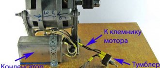
Certain elements of the device will have to be purchased assembled, such as the motor and clamp. Some are purchased separately and ordered in workshops, where they will be made to the required dimensions. The better the steel used, the longer the machine will last.
Base
The best choice would be to use a cast frame from an old non-working machine. The stability of the unit depends on the base. As an alternative, you can weld a frame from channels or profile pipes. You cannot take wood, as it will not be able to withstand the workload.
Electric motor and transmission
For the engine, you can use a device from an old washing machine or other household appliances that have sufficient power. It is also worth considering purchasing a new engine, since the price is not too high.
It is better to use a belt drive. It is much easier to assemble. Also, when using a belt directly on the shaft, there is less impact, and this significantly increases the service life.
Master and slave centers
These two nodes are placed on the same axis. There is also a type of machines that have one leading center. The follower must be placed on the tailstock (it can be rotating or stable). The sharpened end of the bolt is suitable for manufacturing.
Spindle as an element of a lathe
The most important structural component of a lathe is its spindle, which is a hollow metal shaft with a conical inner hole. What is noteworthy is that several structural elements of the machine are responsible for the correct functioning of this unit. It is in the inner conical hole of the spindle that various tools, mandrels and other devices are fixed.
Spindle drawing of screw-cutting lathe 16K20
In order to be able to install a faceplate or a lathe chuck on the spindle, its design includes a thread, and to center the latter there is also a collar on the neck. In addition, to prevent spontaneous unscrewing of the chuck when the spindle is quickly stopped, some models of lathes are equipped with a special groove.
The results of machining parts made of metal and other materials on the machine largely depend on the quality of manufacturing and assembly of all elements of the spindle assembly. In the elements of this unit, in which both the workpiece and the tool can be fixed, there should not be even the slightest play that causes vibration during the rotational movement. This must be carefully monitored both during the operation of the unit and when purchasing it.
In spindle units, which can be immediately determined from their drawing, sliding or rolling bearings can be installed - with roller or ball elements. Of course, rolling bearings provide greater rigidity and accuracy; they are installed on devices that process workpieces at high speeds and with significant loads.
Foundation for a metal processing machine
Preparing a foundation for a machine differs from building a foundation for residential, commercial and industrial buildings.
The created support must be rigid so that the equipment’s operation accuracy is high. It is also necessary to ensure high-quality vibration damping so that they do not destroy the structural elements of the building. You can purchase the machine here: https://st-ok.ru/
The size and structure of the base is determined not only by the weight of the equipment, but also by the type of soil at the installation site and the degree of its moisture content. The machine base is often used in difficult conditions, so it must withstand destructive factors for many years.
The need to secure equipment
One of the fundamental factors for the production of a foundation for a machine is its purpose. The machine is secured to the floor mainly if it is intended for the production of parts with micron accuracy.
Provided that the equipment is mobile and periodically moved, a separate foundation is not required for it; its installation requires a perfectly flat concrete floor or a concrete panel lining, about 15 cm thick. Considering the weight of the equipment, up to 30 tons, its stability cannot be considered worry.
In order to avoid emergency situations in the workshop, turning equipment still requires its own foundation with the laying of routes for communication components that ensure its functionality. Metal pipes for hoses for supplying air, water, and electricity with a voltage of 380 V will reliably preserve the insulating layer and the wires and hoses themselves from deformation.
The height of the platform will depend on the diameter of the pipes and the weight of the equipment. The foundation area is calculated for each piece of equipment separately, which is why it may not have a strict quadrangular shape. It may appear to be created from individual elements put together into a cohesive whole. Despite this design, it is poured in a single slab, and not for each unit separately.
One of the requirements for the foundation for a lathe or an entire complex is that the platform protrudes from under each unit on all sides of the same width.
Picking up and transporting
The equipment removal diagram looks like this:
- Removal of units located in an easily accessible place.
- Removal of heavy units. Dismantling of such units is carried out using special auxiliary means: winches, beam cranes, etc.;
- Analysis of removable units. Assemblies representing a complex mechanism are disassembled into spare parts.
- Special treatment of components with a specific lubricant. It must be taken into account that the removed parts and assemblies can be stored in the open air for a long time, which can lead to loss of presentation, so anti-corrosion treatment is required.
- The main task of preparing equipment for movement is to preserve its working and technical qualities during transportation.
- Certain conditions are also imposed on the transport on which the movement will be carried out. Transport requirements are specified in advance. Any type of lifting work is a high-risk activity. Therefore, before carrying out such work, it is necessary to instruct all employees who will participate in this process.
Foundation for a metal processing machine
Preparing a foundation for a machine differs from building a foundation for residential, commercial and industrial buildings.
The created support must be rigid so that the equipment’s operation accuracy is high. It is also necessary to ensure high-quality vibration damping so that they do not destroy the structural elements of the building. You can purchase the machine here: https://st-ok.ru/
The size and structure of the base is determined not only by the weight of the equipment, but also by the type of soil at the installation site and the degree of its moisture content. The machine base is often used in difficult conditions, so it must withstand destructive factors for many years.
Tool installation
The first stage of setup is the installation of tools. But you can start with installation only after cleaning the components from dust, chips and other contaminants. For this it is recommended to use:
- rags;
- tassels;
- toothbrush.
Then you need to place plugs in the slots and threaded holes that you do not plan to use. After this, you should make sure that the screws are in good condition. By tightening the jaws, you need to block the rotation of the chuck. This condition is ensured by a drive. The keys used to secure the equipment during installation must be in good condition.
Commissioning
Commissioning work is usually carried out by representatives of the manufacturer, but sometimes this function is performed by an employee of an enterprise that has passed the appropriate licensing. Commissioning consists of mutually interfacing the machine components and setting up functional blocks according to the technological map approved by the plant where the machine will be operated.
In addition, the service technician programs the machine's numerical control and optimizes software parameters.
Installation of milling machines on foundations.
Installation of milling machines on conventional foundations must be done after the concrete has hardened. Before installing the machine, the foundation must be marked according to the overall dimensions of the machine in plan.
Due to the insufficient flatness of the foundation, metal spacers with a thickness of 3-10 mm or steel wedges with a slope of 4-5° should be used (Fig. 65, a), the number and location of which is indicated in the drawing. Typically, it is recommended to install wedges around the perimeter of the frame at intervals of 500-700 mm from each other.
The horizontalness of the machine in the longitudinal and transverse planes is checked using levels installed in several places and by tamping wedges to ensure that the installation accuracy corresponds to the standardized one, i.e. 0.04 mm per 1000 mm of bed length.
Rice. 65. Adjusting the position of the machine on the foundation:
a - driving the wedge in with a hammer, b - moving the wedge with a screw; 1 - bed, 2 - wedge, 3 - wedge base, 4 - foundation
Heavy milling machines are mounted on shoes (Fig. 65, b), which are double wedges adjusted by a screw.
After the final alignment of the machines, the bolts are tightened or cement mortar is poured under the supporting surface of the frame.
CNC milling machines, including CNC milling, drilling and boring machines with automatic tool changers (machining centers), are installed on foundations secured with anchor bolts or on vibration supports (lightweight machines) (Fig. 66).
Rice. 66. Installation of a milling machine on a foundation:
a - with fastening with foundation bolts, b - on vibration supports
Rice. 67. Rubber-metal vibration mounts:
a - equal-frequency, b - elastic-rigid; 1 — thrust screw, 2 — threaded adjusting sleeve
Currently, a large number of vibration supports are known, differing in the material of the elastic element (rubber, rubber-metal, metal with felt springs, cork, etc.) and design solutions. Among rubber-metal supports, the most common are equal-frequency supports EV-31 and OV-33 (Fig. 67, a).
For equal-frequency supports, the stiffness is approximately proportional to the load, and therefore the frequency of natural vibrations of the machine depends little on the load on the support. This significantly simplifies the selection of supports, since there is no need to calculate the support reactions from the mass of the machine, but only need to determine whether the load on the support exceeds the maximum permissible. The advantages of equal-frequency supports compared to supports with a linear characteristic is that changing the mass of a part or moving heavy machine components does not overload the supports. Therefore, one standard size can be used to install different machines.
To change the rigidity of the support in different directions, and this is especially important for machines with heavy reversible units or working with shock loads, a special insert can be inserted into the support. Vibration supports have a device for leveling the machine; For different supports, the height adjustment ranges from 8 to 15 mm. The special design of the lower base of the supports ensures good adhesion to the floor surface
The service life of vibration supports is at least 10 years
The special design of the lower base of the supports ensures good adhesion to the floor surface. The service life of vibration supports is at least 10 years.
The accuracy of machine installation on rubber-metal supports is lost over time due to the creep of rubber. To reduce the loss of accuracy, lock nuts should be secured to the supports, and the machines should be re-leveled three to four days after installation. The machine is aligned with the moving parts in the middle position.
The machine, mounted on elastic supports, can tilt when moving the moving parts. Therefore, when checking the installation of a machine for its compliance with accuracy standards, it is necessary to use two levels - one installed on a non-deformable part of the bed to record the general inclination of the machine on the supports, the other on the stationary unit of the machine. Reconciliation is carried out based on the difference in readings of these levels.
At significant angles of inclination, it is advisable to use elastic-rigid supports (Fig. 67,b), which allow you to quickly move from an elastic installation to a rigid one without changing the location of the machine.
This is achieved by rotating screw 1 until it stops at the base; Height adjustment is performed by rotating threaded bushing 2.
Source
DEVICES FOR INSTALLING AND ALIGNING MACHINES
When installing, regardless of the foundation group, the machine must be accurately aligned to horizontal or vertical. To facilitate and speed up installation, special devices are used that are placed between the base of the machine and the foundation.
Flat metal pads with a thickness of 0.3–1 mm are currently almost never used due to a number of disadvantages:
a) adding or removing pads involves the need to lift the machine each time, which is done either with a crane or crowbars manually, which is always accompanied by the danger of moving the machine from its installation site;
b) stepwise adjustment and the need to have a large set of different pads, which are easily clogged, bent, or lost;
c) the rigidity of installation on such pads is insufficient due to numerous joints and insufficient smoothness and straightness of the pads.
| Rice. 3. Steel wedge |
Setting wedges (Fig. 3) are widely used for installing light and medium-sized machines of normal and reduced accuracy. Wedges are placed around the perimeter of the base at intervals of 500 - 600 mm. If the machine is installed on the foundation of the second group, then the wedges should be located as close as possible to the foundation bolts. When aligning, the position of the machine can be smoothly changed by tapping wedges.
| Rice. 4. Installation shoe |
Installation shoes are used for mounting medium and large machines. They can also be used to install precision machines. The shoe consists of a durable body and a wedge (Fig. 4), which can be moved with a screw using two nuts. In this case, the screw does not bend, since it can move freely along the vertical slot of the rack. Oblong holes in the wedge and the base of the shoe allow the foundation bolt to be passed through them freely, if necessary.
At the end of the alignment, the screw is firmly locked with the same two nuts. The figure shows the approximate dimensions of an average shoe. Installation shoes are placed at intervals of 1 - 1.5 m but not less than three or four under the machine.
| Rice. 5. foundation slab element |
Foundation slabs are used exclusively for the installation of large and especially precision machines. The foundation slab is made of fairly massive cast iron (Fig. 5). In relation to the machine being installed, shoes similar to those discussed above are built into the plate every 1–1.5 m. The slab is embedded in the upper part of the foundation during its laying and is connected to it either with special dowels protruding from below, or is attracted by special bolts embedded in the masonry. The entire foundation plate protects the machine from deformation in the event of uneven settlement of the foundation. In all cases, it is easy to make the machine horizontal by adjusting the shoes.
Convenient, but less common means of machine alignment include alignment using bolts located at the edges of the base of the bed along its entire perimeter. The machine in this case rests on the supporting ends of the bolts, which in turn must rest on sufficiently thick steel plates. Once the machine has been aligned, the bolts are secured with locknuts.
The second group of devices for installing machines consists of foundation bolts. They must provide a sufficiently rigid and strong connection of the frame with the foundation of the second group. The clamping force developed by the bolts, together with the weight of the machine, causes frictional forces between the base of the frame and the foundation, which always exceed the shear forces that can arise and act on the machine. This is also facilitated by the cement bead formed after gravy around the sole of the machine. Therefore, foundation bolts only work in tension. From experience it has been established that foundation bolts with a diameter of less than 14 mm should not be used, since they become deformed (“flow”) when tightened. When fastening light and medium-sized machines with foundation bolts with a diameter of more than 14 mm, they are usually not checked by calculation. It is recommended to calculate bolt diameters for heavy machines.
| Rice. 6 Mounting unit of the machine on the foundation of the second group |
The length of the foundation bolts is determined from the condition of equal strength of the bolt in tension and the strength of the foundation masonry in tension. The section of the masonry working on tearing is taken in the form of an overturned truncated pyramid (Fig. 6) with an angle of 2p at the apex.
In table Table 2 shows the values of the minimum embedding length of foundation bolts for various masonry materials, obtained on the basis of calculations.
table 2
| Diameter of the foundation block, mm | Foundation material | ||
| Concrete | Brick | Booth | |
| 14 | 140 | 160 | 300 |
| 16 | 170 | 200 | 350 |
| 18 | 190 | 260 | 450 |
| 22 | 250 | 280 | 450 |
| 24 | 260 | 300 | 550 |
| 27 | 280 | 320 | 550 |
| 30 | 320 | 360 | 550 |
| 36 | 380 | 420 | 750 |
| 42 | 460 | 500 | 750 |
| 48 | 500 | 600 | 850 |
To ensure reliable fastening, the edges of the wells for the bolts are made with a slight slope.
In fig. Figure 6 shows a correctly completed filling of the machine with cement mortar.
Structurally, foundation bolts differ mainly
design of the tail section (Fig. 7).
There are foundation bolt designs that do not require grouting; such bolts are called anchor bolts and can be easily dismantled.
When laying a foundation near the bottom of a straight well, an anchor plate is sealed (Fig. 8), onto which a bolt is then attached. To do this, pass the rectangular head of the bolt through the same hole in the plate and then turn it 90° until it stops. After this, the bolt is tightened in the usual way.
Rice. 7.Structural types of foundation bolts |
All other things being equal, the length of the anchor bolt can be taken less than the length of the foundation bolt, since the anchor plate increases the surface of the section of masonry to be torn off.
Anchor bolts are rarely used and only for fastening heavy machines.
Preparatory work before installing the lathe
The lathe is usually supplied in a single, integral package or box. Depending on the type of machine, its purpose, and, consequently, the weight and size of the installation work can also be different. After receiving the machine to the production workshop, you should:
- make calculations on the size and density of the support for the machine;
- prepare a place for installing the machine;
- properly unpack the machine using chucks or other hydraulic tools.
The main task of a lathe is to provide a smooth, strong, stable support necessary for metal processing. Therefore, all installation work is reduced to ensuring the maximum degree of stability, strength and reliability
It is very important to dampen all possible vibration effects that may occur during work.
Purchase of machines and equipment today
Call the single phone number of VtorMetall LLC
+7
or order
Back call
PAYMENT IS MADE IN A FORM CONVENIENT FOR YOU
Frequently asked questions from our clients
- What is the minimum weight of machines and equipment for sale?
In most cases, we accept scrap machinery and equipment weighing over 100 kg. It all depends on what type of scrap metal you are going to hand over, its contamination, total weight and method of delivery to the nearest recycling point. - How can I find out the exact price of machines and equipment over the phone?
In order to get the most accurate price for machines and equipment, we will need a photograph of the entire batch of this category. Send a photo to our WhatsApp and we will advise you on the cost within 3 minutes.
- Why did the operator name one price, but in fact it turned out to be different?
Only the total weight of this scrap metal and its contamination can affect the final cost of machines and equipment. In other cases, the price cannot change! Call our single number +7 and get a free consultation.
- Can you offer me special conditions?
Of course we can! To do this, you need to hand over scrap machinery and equipment over 2 tons, or be our regular customer. Call us on one phone number and we will definitely come to an agreement!
Transportation of a lathe
Transporting equipment is difficult and has its own peculiarities
It is important to properly secure the moving parts of the machine; some elements must be transported separately
Features of lathe truck transportation:
- Special equipment of the vehicle with spacers or mounting profile;
- Availability of equipment for reliable fastening of equipment;
- Fastening is carried out with special straps diagonally for stability;
- Compliance with the speed limit (during emergency braking, a high load mass can change the trajectory of the vehicle);
- Use of low profile trailers to facilitate loading and unloading.
Our specialists will deliver the lathe professionally and efficiently, guaranteeing the safety of the equipment.
Preparing floors for installation of a metal processing machine
An intermediate stage in the process of putting any machine into operation is its correct installation. Based on the weight of the equipment, it is installed directly on the floor or on a separately constructed base. The location for it is selected at enterprises according to a plan, and at home - arbitrarily, where it is convenient. Preparing the floor for the machine is an important point on which the stability of the unit during operation will depend. The foundation must be strong enough to withstand dynamic and static loads from the equipment. If necessary, it is strengthened.
Regulations
Regulatory documents that must be followed for dismantling, rigging, transportation and installation and commissioning of the transformer:
GOST 12.3.009-76 “SSBT. Loading and unloading works. General safety requirements"
Guidelines for fastening technological equipment with foundation bolts (SN 471-75)
GOST 24379.0-2012. Foundation bolts. General technical conditions.
SNiP 3.05.05-84 Process equipment and process pipelines
VSN 362-87 Manufacturing, installation and testing of process pipelines up to 10 MPa
VSN 70-79 Instructions for installation and testing of pipelines with a nominal diameter of up to 400 mm inclusive for pressures over 9.8 to 245 MPa
SN 527-80 Instructions for the design of steel pipelines up to 10 MPa
GOST 21.401-88 System of design documentation for construction. Production technology. Basic requirements for working drawings
Collection E26 Installation of process pipelines
We will professionally carry out rigging of a lathe in Moscow and the Moscow region, we also have partners throughout Russia and the CIS countries, and will also dismantle the lathe, install a foundation for the lathe, carry out maintenance of the lathe and its modernization.
Lathe rigging
Rigging work includes: loading, moving, unloading equipment.
The lathe has a large mass. Therefore, during work it is necessary to comply with technical safety rules. Lathes weigh from 300 kg to 5 tons
Before you begin rigging the machine, you need to make accurate technical calculations, measurements of units and openings, and take into account the technical characteristics of the equipment. Draw up a transportation plan so as not to clutter up the site where the lathe is planned to be installed and not to paralyze production.
Experienced specialists of our company will carry out professional rigging of the lathe using lifting equipment and equipment (turnbuckles, ropes, belts, slings, chains, trolleys, forklifts and truck cranes).
Basic rules for rigging work:
- The workspace must be equipped with flooring and racks for spare parts;
- Large elements are screened with a wooden frame and signal flags are glued on;
- Moving units are fixed in a static, stationary state;
- Auxiliary parts (nuts, fasteners) are packaged in separate cases with tags.
24-hour dismantling of machines and equipment in Moscow
After dismantling the machines or equipment, you can hand over your equipment to our collection points, presenting write-off certificates and receive a high monetary reward. The cost of scrap metal varies depending on the quantity of non-ferrous and ferrous metals, their quality characteristics, as well as sorting and clogging. If you need all metal junk removed from your property, then you can use our 24-hour metal removal service today.
| Name of service for removal of machinery and equipment | Price for removal of machines and equipment |
| Loading scrap machines and equipment with special equipment | From 1550 rub. for 1 shift |
| Removal of metal waste (from 6 to 37 cubic containers) | For free |
| Removal of machines and equipment by gazelle up to 1 ton | from 1100 rub. |
| Removal of machines and equipment by gazelle over 1 ton | For free |
| Removal of machines and equipment by KAMAZ up to 3 tons | from 4100 rub. |
| Removal of machines and equipment by KAMAZ over 3 tons | For free |
| Removal of machines and equipment by scrap truck up to 35 tons | Negotiable |
| Removal of machines and equipment by scrap truck over 35 tons | Negotiable |
See all prices
The total amount of payments is determined after calculations based on the assessment of the total lot. You can find out today’s average prices for 1 ton of ferrous or 1 kg of non-ferrous metals on our company’s website or by contacting a specialist at our equipment dismantling points +7 (499) 343-02-32 [www.lom-msk.ru ].
Construction of the equipment base
The construction of the simplest slab-type base, for a machine or a low-power press, proceeds as follows:
- First you need to determine the location of the base. The foundation should not come into contact with the walls, columns or internal partitions of the building itself. The minimum distance from the press foundation to the workshop foundation is 100 centimeters. Otherwise, the vibration will transfer to the base of load-bearing walls, columns or partitions.
- After this, you should determine the position of the fastening (foundation) bolts securing the frame of the press or machine. It should be taken into account that the minimum distance from the edge of the foundation to the axis of the bolt is 20 centimeters. That is, the foundation should protrude beyond the edges of the frame by at least 20-30 centimeters.
- Having determined the above parameters, you can begin excavation work (digging a pit). Moreover, the depth of soil excavation in an unheated workshop is equal to the freezing depth + 25-40 centimeters. In a heated workshop, the depth of the foundation is 50-80 centimeters. The dimensions of the pit itself are equal to the width and height of the foundation + the depth of the base. After all, the walls of the pit, as a rule, are arranged at an angle of 45 degrees.
- Having completed the excavation work, you can begin to increase the bearing capacity of the soil by adding a two-layer sand and gravel cushion to the bottom (15-20 centimeters for each fraction).
- The next stage is the construction of formwork surrounding the contour of the foundation. It is assembled from removable metal or wooden panels connected by transverse ties.
- At the next stage, a reinforcing frame is introduced into the internal cavity of the base (in bases for small machines you can do without a frame), and the bottom of the formwork is covered with a layer of waterproofing (roofing felt). In special cases, a special material is placed at the bottom of the base to dampen vibration (oak timber or something else).
- After this, the internal cavity is filled with concrete, laying the solution in layers of 10-15 centimeters.
The foundation is considered ready for use after 25-30 days from the moment of pouring. During this time, the base monolith will reach its design strength. Before this period, the equipment is not installed on the foundation.
https://youtube.com/watch?v=XhQNw0SPNT4
Lathe - equipment that requires installation on a foundation
To ensure the safety of its use for workers and to minimize breakdowns of the equipment itself, special attention must be paid to preparing the foundation
The unusual thing about the foundation for turning equipment is that when designing it, it is necessary to take into account the supply of compressed power and power supply. Grounding bolts are required in the system. In addition to the machine itself, depending on the model, the following can be installed on this concrete platform:
- conveyor that removes chips from the workplace;
- hydraulic station with a water supply and discharge chute;
- electrical cabinet
Assembly technology of screw-cutting lathes.
Assembly of metal-cutting machines is carried out in accordance with GOST 7599-82. There are 5 accuracy classes of machine tools: N, P, B, A, S. The assembly of metal-cutting machines, and in particular lathes, is a typical example of unit assembly in mass production.
Assembly of machines in serial and large-scale production is carried out on conveyors (machines of class N and P); in single and small-scale production they are assembled on panel stands. Class B, A, C machines are assembled on special foundation assembly stands.
Parts entering the subassembly and assemblies entering the general assembly must be clean and free of traces of various contaminants. The treated surfaces must be free of mechanical damage (cracks, dents, nicks, etc.) that impair the performance properties or appearance of the machine.
Surfaces after scraping should not have traces of previous mechanical treatment. The scraping of the guides must be uniform along the entire length and, when checking for paint, it must contain in a 25 x 25 square at least 12 spots for machines of class H, 16 spots for machines of class P, 20 spots for all other machines (classes B, A, C) .
After studying the design of the machine, identifying the relationship of all assembly units and parts, and conducting a dimensional analysis, they begin the general assembly of the machine. At the same time, the design features of the machine, ease of assembly, the possibility of mechanizing assembly work, and reducing fitting work to a minimum are taken into account.
The general assembly of a machine type 16K20 after assembling its components is carried out in the following sequence (one of the possible options):
1) installation of the main electric drive, lubricant and coolant tank, connection of electrical wiring harnesses to electric motors, limit switches, electromagnetic couplings. All these components are placed on pedestals or in pedestals of the machine.
2) installation of frames on cabinets, installation of a pallet. During installation, a tight fit of the parts is ensured to prevent deformation of the frame when fastening it. If necessary, the mating surfaces are scraped. You should also ensure that the bolts are tightened evenly to avoid deformation of the frame.
3) installation of the longitudinal support slide or carriage. During installation, a tight fit of the mating surfaces is ensured; control is carried out using paint or a probe. If necessary, scraping or grinding of the carriage guides is carried out. The smooth movement of the carriage along the guides is controlled.
4) installation of the headstock with gearbox. During installation, the correct fit of the supporting surfaces is ensured and, if necessary, the surface of the bed is scraped along the mounting surface of the headstock body. Control is carried out using paint or a probe. The parallelism of the spindle axis to the bed guides or the longitudinal movement of the carriage is controlled. Control is carried out using a mandrel installed in the spindle of the machine and an indicator located on the carriage and moved along the stroke length. Control is carried out in two mutually perpendicular planes when the spindle is rotated 180°. Deviation from parallelism in the vertical plane is 0.0016 at a length of 200 mm for machines of class H and 0.01 at a length of 200 mm for machines of class P. In the horizontal plane 0.008 at a length of 200 mm for machines of class H and 0.05 for machines of class P .
After installing the headstock, the influence of the installation of the headstock and the level position of the beds is also monitored. The tightness of the supporting surfaces is checked with paint and a feeler gauge, the radial and axial runout of the spindle axis, the end runout of the spindle support shoulder, the radial runout of the axis of the conical surface of the spindle at the end, etc. are monitored;
5) installation of the feed box. During installation, the correct fit of the supporting surfaces and their relative position are ensured; the required position of the feed box is achieved either by moving it along the frame or by scraping the supporting surfaces. Control is carried out using paint or a probe;
6) installation of the upper or transverse support. During installation, the support guides are perpendicular to the frame guides or the spindle rotation axis. Control is carried out using a special mandrel 1 installed in the machine spindle and indicator 2 on the support (Fig. 2). Control is carried out in two mutually perpendicular planes when the spindle is rotated 180°; deviations from perpendicularity are 0.0012 at a length of 200 mm for H machines and 0.0008 at a length of 200 mm for P machines. If necessary, the dovetail of the caliper guides is scraped;
7) installation of the apron, lead screw, lead shaft and rear bracket for the lead screw and roller. The apron is installed using bolts on the carriage; the position of the lead screw is installed and aligned parallel to the guides. The roller is installed and aligned parallel to the guides. The parallelism of the lead screw and the lead roller is controlled using a special bridge with indicators or an indicator mounted on a special plate moved along the frame guides. The rear bracket is positioned for the lead screw and the lead shaft, the gear rack is screwed to the frame, the position of the gear wheel relative to the rack is verified, and the apron is finally fastened. After installing the lead screw and lead roller, their position and axial runout are monitored, which for N machines is 0.0008 at a length of 400 mm and 0.0005 at a length of 400 mm for P machines;
Figure 3. Control circuit using a special bridge
Figure 4. Control circuit using a special plate

| a) |
installation of the tailstock.
During installation, the tight fit of the tailstock body to the guides and the alignment of the spindle and quill axes are ensured. Correct fit is ensured by scraping or grinding the supporting surface of the tailstock housing. The alignment of the spindle and quill axes in the horizontal plane is achieved by shifting the tailstock body using the adjustment method, and in the vertical plane by scraping the supporting surface of the tailstock using the fitting method. After installing the tailstock, the parallelism of the quill axis is checked by moving the caliper using an indicator at a length of 400 mm. The deviation from coaxiality in the vertical plane is for H machines - 0.003 at a length of 400 mm and for P machines - 0.002 at a length of 400 mm. The same height of the spindle and quill axes in the vertical plane is 0.003 for N machines, and 0.002 for P machines. Alignment is determined by installing a control mandrel in the centers of the machine using an indicator mounted on the machine support (Fig. 6). Fig.5
Fig.6
9) installation of the guitar body. The gears of the guitar engage the gearbox and feedbox;
10)
machine testing. carried out in a static state (smooth movement), tested at idle, under load and special tests (for accuracy, rigidity and vibration resistance);
11) final finishing, painting, preservation and packaging. General requirements for the accuracy of machine tools according to GOST 8-82.
Shaft installation
Shafts in various machines are used to support rotating parts (couplings, gears, bushings, etc.), workpieces, tools, etc. Quality indicators for mounting shafts on bearings are:
— Ease of shaft rotation in bearings;
— No vibration during rotation;
— Radial and axial runout within specified limits;
— Accuracy of the shaft position relative to the main housing bases in which it is installed;
The degree of accuracy of shaft installation is determined by its service purpose. When mounting shafts on plain bearings, it is necessary to ensure a gap between the shaft support journals and the bearing bushings. The size of the gap is determined by the service purpose of the shaft.
Before assembling the shafts, the quality of manufacturing of the housings and bearing bushings is monitored, errors in the shape of the bushings, deviations from the perpendicularity of the end of the bushing axis, and radial runout of the cylindrical surfaces of the bushing are monitored. The working surfaces of the mating parts must be free of various defects (sinks, scratches, nicks, etc.), the error of the hole in the body should not exceed ½ the tolerance for the hole diameter. The roughness of working surfaces is not higher than Ra 1.25 microns.
In general, the deviation of the gap from the required value is determined by the following reasons:
— errors in the shape of the shaft bearing journals and bearing bushings in the longitudinal and cross sections (cone-shaped, saddle-shaped, oval, cut, barrel-shaped).
— misalignment and spatial intersecting of the axes of the bearing journals and bearing bushings.
Reducing the guaranteed clearance can cause the shaft to become stiff or even jam. The radial runout of a shaft surface is considered relative to its specific surface. When installing a shaft on two supports, the radial runout of any of its surfaces is the result of the runout of this surface relative to each of the supports.
As an example, consider the radial runout of the surface of a conical hole in a machine spindle mounted on two sliding supports (Fig. 7).
Fig.7
In this case, the radial runout of a given surface is the result of the summation of runout errors relative to the front and rear spindle supports, determined by the corresponding dimensional chains.
Links A1 and B1 characterize the misalignment of the surface of the conical hole relative to the shaft support journal. Links A2 and B2 characterize the misalignment of the shaft support journals and the holes of the bearing bushings. When combining the components of the radial runout in one plane, its value is determined: E=AD+BD.
The errors of links A2 and B2 depend on the distance between the supports and the location of the shaft section, in which the radial runout relative to each of the supports is considered. So, for example, if the runout of the rear support is equal to 0, then in the front support it will be equal to the value a, and at the front end of the spindle - to the value b, that is, at the front end the runout value increases (Fig. 8). If the runout in the rear support is equal to some value k, and in the front support it is equal to 0, then the output will be a value of L, that is, the runout value will be reduced. As a result, it is necessary to introduce correction factors when calculating tolerances for the component links of the dimensional chain.
Where g1 and g2 are correction factors.
Rice. 8
Axial movements when mounting shafts on plain bearings arise due to gaps between the ends of the supporting surfaces and shafts and due to the non-perpendicularity of the ends of the supports and the shafts themselves to the axis of the rotating shaft. Axial clearances are ensured during assembly using the adjustment method.
When taking into account deviations from the perpendicularity of the end surfaces, proceed from the following:
— axial movements occur in the event of deviations from the perpendicularity of the ends of the mating surfaces. If one of the mating surfaces does not deviate from perpendicularity, then there is no axial movement (Fig. 9);
—
Of the two effective errors in deviations of the ends from perpendicularity, the smaller error always acts, which is a feature of the summation of errors in the dimensional chain that determines the axial movement of the rotating part when the selective summation law is in effect.
Non-perpendicularity of the end surfaces of the mating parts can lead to stiff movement of the shaft or to jamming. To reduce axial movement, it is necessary to reduce the tolerances for deviations from perpendicularity and the number of mating pairs of parts.
After assembling the shaft, it is run-in at low loads and the frequency of the rotating ends, gradually bringing their values to nominal. The heating temperature of the bearings should not exceed 60° C. Depending on the technical requirements, radial and axial runout, the presence of seizure during installation and startup of the machine, and the noise level are monitored.
When mounting shafts on rolling bearings, the required accuracy is achieved by interchangeability and adjustment methods. Ease of shaft rotation is ensured by a given guaranteed clearance. The amount of radial runout of shafts on rolling bearings is influenced by the bearings’ own runout. The magnitude of the radial runout in the shaft section under consideration is determined by the distance between the shaft supports or the location of the shaft section in which the radial runout is considered relative to each of the supports.
Let's consider a diagram of dimensional chains that determine the magnitude of the radial runout of the conical surface of the machine spindle when installing it on rolling bearings (Fig. 10). Links A1 and B1 – characterize the misalignment of the surface of the conical hole relative to the support journals. Links A2, B2, A3 and B3 - characterize the own runout of the bearings.
Rice. 10
In general, reducing radial runout by regulation can be done as follows:
— selection of bearings so that the eccentricities of the holes of the inner rings in relation to the running tracks of the outer rings are equal to the eccentricities of the corresponding bearing journals in relation to the section under consideration.
— installation of shafts and bearings is carried out in such a way that the eccentricities mutually compensate each other. To do this, the eccentricity errors of each of the supports must be in the same plane, but located in opposite directions.
The condition for mounting the shafts is to ensure that the shaft axis is parallel to the main base of the body part within specified limits in two coordinate planes.
When mounting bearings on shafts, they are heated in electric oil baths to a temperature of 70-80°. When installed in a housing, they are cooled with solid carbon dioxide or the housing is heated.
The assembled unit is monitored for heating and noise levels.
Regulations for arrangement
Above we discussed the basic requirements that any foundation intended for installing industrial equipment on it must satisfy. However, there are other requirements - for the foundation for equipment with dynamic loads, which it must meet.
Design work, as well as the practical part of arranging the foundation, should be carried out only by competent specialists who, in addition, also have experience in carrying out this type of work. In order to create a correct and complete project, it is necessary that all the required data is available. During the construction of the foundation for the equipment, it is necessary to periodically carry out quality control. It is very important that the actions of all participants in the work process are strictly coordinated. Those foundations that have already been erected should be used only with the equipment for which they are intended. There is technical documentation for this. For construction, you can use only those materials that are suitable according to the design documentation. In the future, it is necessary to carry out maintenance of the foundation so that the structure can be used for as long as possible. It is recommended to use the simplest possible parts as fastenings.
For example, these could be anchor bolts that are embedded in concrete.
Technical conditions for the manufacture of the foundation.
For normal precision machines: Soil bearing capacity 5kg/m2. If necessary, load the foundation with an additional load (concrete blocks, blooms, etc.) exceeding the weight of the machine by 3-4 times and check the elevation marks with a level on a benchmark not connected to the foundation every day until the end of shrinkage. For high-precision machines: The foundation must be made with free side edges and heavy concrete of design grades must be used with a compressive strength of 150-200 kg/cm2. To fill the foundation, use a concrete mixture with a volume ratio of cement-sand-crushed stone of 1:1:3 (concrete grade not lower than M250). Foundation depth H > 0.6 √F, where F is the area of the foundation. The foundation is reinforced with a single lattice along the length, width and height with a cell size of 200 mm. The diameter of the reinforcement depends on the size of the foundation and can be from 12 mm to 20 mm. Strength of foundation concrete. Installation of the machine can be allowed when the concrete reaches a compressive strength of at least 50% of the design strength (approximately corresponding to seven-day concrete). By the time the machine is started, the concrete strength should be at least 70% of the design strength (approximately equivalent to 15-day concrete). The period for complete hardening of concrete is 28 days. The quality of concrete is controlled by the strength of control cubes 200x200x200 mm. The strength of concrete in a finished foundation can be roughly estimated by sound and impact.
Installation and adjustment of lathes
Installation and adjustment are preliminary work to prepare machines to perform the necessary work, taking into account all technological processes that help achieve the required quality of the manufactured product. In order to establish the required operating mode of the machines, they are additionally configured, that is, the machines are prepared to perform certain functions using established technologies. Before starting work, you need to make sure that the machines carry out all the necessary commands and operate without deviations from the prescribed norm. If the machine works without interruptions, you can begin to set it up.
After the machines have been set up, they need to be configured. Before setting up the machines to perform the necessary functions, they must be switched to a neutral non-working position. First, the feed and main movement chains of the machines are adjusted, then the speed is adjusted in order to obtain the required cutting speed. With the correct choice of mode for cutting metal, it is possible to fully use all the working capabilities of machine tools and, accordingly, cutting tools.
Why you should entrust equipment installation to professionals
Some of the main reasons to entrust installation and assembly work to an experienced professional company are the following.
- The machine equipment to be installed is large in size and weight. Violation of safety precautions by untrained people can lead to injury to workers themselves and damage to the production building.
- Mounted machines have a high price - 100–200 thousand euros per machine. One wrong action leads to their damage and large losses.
- Installation, assembly, installation of equipment - work that requires special technical knowledge and practical skills. Without this, it is impossible to correctly assemble the elements of a complex machine and organize its operation.