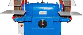
DESCRIPTION TRIOD SP-2000
TRIOD SP-2000 is a roughing and grinding machine designed for sharpening, polishing, finishing of both cutting tools and parts of various materials. TRIOD sharpening machines are highly reliable and durable in operation. SP-2000 has: a strong cast iron body, fully sealed bearings, adjustable protective screens, adjustable supports, holes in the body for mounting on a workbench. Includes: roughing and finishing grinding wheel, grinding wheel protection. The homeland of the brand is Russia.
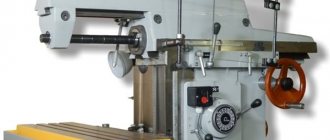
3B633 Floor-mounted grinding and grinding machine. Purpose, scope
The sharpening and grinding machine with two wheels model 3B633 is designed to perform the following operations:
- a) sharpening of cutters up to 50 mm high (high-speed and equipped with carbide plates);
- b) sharpening of drills with a diameter from Ø 6 to 25 mm and from Ø 12 to 50 mm;
- c) metalworking work (removal of burrs, chamfers, etc.);
- d) sharpening metalwork tools;
- e) grinding parts with an abrasive tape;
- e) polishing of parts.
Design features and operating principle of the machine
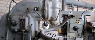
The main components of the 3B633 sharpening and grinding machine are: bed, head, wheel mounting, protective covers, rotary table, tool rest and electrical equipment.
The controls of the machine are a spindle speed switch (Figure 2), a control button with a black pusher “Start”, a control button with a red pusher “Stop”, and a rotary table moving handle.
Accessories are supplied with the grinding machine.
The kinematic diagram of the machine consists of a motor whose shaft is a spindle. This diagram is simple and therefore is not included in the manual.
Machine bed
The upper supporting surface of the frame has two windows that connect the internal cavity with windows for cooling located in the electric motor of the head. The panel with electrical equipment is mounted on four bosses inside the frame. An opening in the front wall, hermetically sealed with a door, allows access to electrical equipment. A control panel with a push-button station and a spindle speed switch is mounted on the front wall of the frame.
Roughing and grinding machines
Ferrous metallurgy plants operate more than 500 abrasive machines for power and high-speed grinding of rolled products.
Every year 20-30 new machines are put into operation, but this does not correspond to the need for machines, which is satisfied by about half. The number of models of these machines has exceeded 50. A significant amount of work is still performed on manual sanding machines, which are still necessary when sampling local defects (Fig. 72). The complete elimination of manual hanging and stationary sanding machines should be carried out in two main directions: 1. Improving the technology of grinding on mechanized machines by creating significantly more resistant abrasive wheels with greater productivity in removing chips per unit of time with the existing self-sharpening efforts and the use of grinding waste during smelting metal For processing high-speed steels, as already indicated, this way of solving the problem can be considered found.
The solution to this problem in a patent is of some interest. It is reported that an attempt was made to equip hand-held machines with high-strength alumina wheels, but such wheels quickly became greasy due to insufficient self-sharpening force on these machines. Coarse-grained wheels were made from natural abrasive materials: spinel (MgO*Al2O3) and mullite (3Al2O3*2SiO2) using technology for high-strength wheels. Tests of these circles gave positive results (Fig. 73).
Improvement of manual machines can also be carried out by using endless coarse-grained abrasive belts, which in laboratory conditions with a drive power of 7 kW and a grinding speed of 25 m/s showed an average productivity of 8 kg/h of removed chips with a durability of 40 minutes of machine time.
2. Development of maneuverable automatic devices for sampling local defects. The creation of such devices is hampered by the lack of an automatic sensor for determining the depth and location of surface defects in the workpiece, as well as the lack of a grinding head design with additional degrees of freedom that exceeds the capabilities of a suspended emery machine. The introduction of machines for sampling local defects should be carried out at the achieved level of grinding technology and tools, i.e., ensure normal sanitary and hygienic working conditions, full use of waste, including remelting of grinding chips, and high tool life with a sufficient level of self-sharpening.
Universal stripping machines with a movable table, a common layout of which is shown in Fig. 74, made it possible to mechanize the labor-intensive operation of continuous stripping of the surface of the semi-product, increase labor productivity by 3-5 times, and reduce the cost of stripping. The cost of processing 1 ton of rolled products on these machines is 8.0–18.0 rubles, 50–70% of which falls on the share of abrasive tools due to the relatively low durability of the wheels (the grinding coefficient is 2–3).
Technical and economic indicators of stripping on the KhSh7-02NZ machine are given in Table. 33, from which it follows that the main influence on costs is exerted by the volume of defective metal and the weight of the workpiece. The most widely used machine in domestic factories is mod. M7400 and various options for modernizing this machine (Table 34). Processing of workpieces is carried out on a horizontal table made in the form of a welded box-shaped structure.
The table moves on rollers along the frame, which is a welded or cast structure. During processing, the workpiece is clamped in a vice. The table drive hydraulic cylinder is installed on the frame and moves the table in the longitudinal direction through a rack and pinion transmission. The grinding head of the machine moves vertically along the carriage guides. The movement is carried out by a pneumatic cylinder. The spindle of the abrasive wheel is placed in a cast housing on rolling bearings. Rotation is transmitted to the spindle via a V-belt transmission; the belts are tensioned as a result of the movement of the electric motor.
The carriage on which the grinding head is located has the ability to move transversely along roller supports and guides. The carriage is moved by a hydraulic cylinder.
The machine has a loading device, which is a frame with inclined rails and a chain conveyor for feeding workpieces. The conveyor drive consists of an electric motor and a gearbox. The processed workpieces are unloaded into the pocket.
The control of the machine is concentrated on the remote control. The table reverse in automatic mode is carried out by adjustable cam stops, in manual mode - from the operator control handle.
The stripping productivity of square workpieces made of steel 12Х18Н10Т on M7400 machines is about 5000 t/year.
Universal roughing and grinding machines are quite simple in design, reliable in operation, their utilization rate in most factories is 0.75-0.85.
The improvement of universal machines occurs on the basis of improving their layout, which is mainly determined by the size, shape and weight of the metal being processed, as well as improving the main components.
The most widely used are pendulum-type grinding wheels mounted on movable carriages or portals. Grinding wheels with feed in a vertical plane have also found use. Planetary type grinding wheels are known.
AC and DC electric motors are used as a grinding wheel drive on these machines, providing grinding speeds of 60-80 m/s or more. Rotation from the electric motor to the grinding wheel spindle is transmitted by V-belts or toothed belts, the tension of which is carried out by the movement of the electric motor.
There are known designs of machine tools in which hydraulic motors are used as a drive, directly rotating the machine spindle. This design allows for increased maneuverability of the grinding wheel.
Most machines have three types of feed: longitudinal, transverse and feed for cutting into a circle. Work is underway to provide the wheel with additional oscillating feed, which increases the maneuverability of the wheel when sampling local defects. Feeds are carried out from separate drives with stepless regulation. To create a clamping force, hydraulic and pneumatic cylinders and electric motors with gearboxes are used; it is known to use springs for elastic compression of the grinding wheel. The mutual movement of the units occurs, as a rule, along roller guides.
Machine tables are made primarily in the form of rigid welded box-shaped structures, on which are placed locking and tilting mechanisms, operating mode control devices, and shock-absorbing devices that ensure reliable movement of the table to its extreme positions. Hydraulic cylinders are used as a table drive, the rods of which are made in the form of racks, meshing through an intermediate gear with a stationary rack placed on the lower plane of the table. Due to the increase in the speed of movement of tables, a rope table drive system is being used.
Round rolled products are moved along a roller conveyor; to turn the rolled products, the roller conveyor rollers are profiled.
Moving, turning and fixing when processing rolled products are the most unresolved issues. In recent years, for these purposes, quite complex, but providing maneuverability during processing, rotary-feeding mechanisms have been created.
There are a significant number of schemes and designs of fixing and moving devices, which is explained by the wide range of processed sections in terms of sizes and shapes of rolled products.
Machines, both operating autonomously and built into mechanized lines, are equipped with loading and unloading devices of various designs.
Universal machines, as a rule, have automatic (for operations of continuous stripping and brightening with a “snake”), semi-automatic and manual control. The latter is used when sampling local defects and is carried out using a mnemonic handle.
Recently, considerable attention has been paid to the designs of dust removal systems, which simultaneously ensure the collection of grinding waste for subsequent remelting. In Fig. Figure 75 shows a diagram of a dust collection device and a settling tank for collecting large metal components of grinding waste. To ensure normal sanitary and hygienic conditions on universal machines, dust suction devices must provide a suction capacity of at least 6000 m3/h.
However, the further development of these machines is beginning to be hampered due to increasing losses of usable metal, insufficient processing productivity that does not correspond to the capabilities of modern abrasive tools, and the high metal consumption of the equipment (see Table 35).
A significant number of advanced roughening and grinding machines operating in metallurgical plants were manufactured in the GDR at the Heinrich Rau enterprise (Table 35).
These machines are unified. The main layout of the machine includes a grinding complex, a movable table, a table frame, a loading table, an unloading device with a pocket, and a control panel. The machines are supplied complete with ventilation units. A distinctive feature of the machines is the inclined arrangement of the table with the workpiece being processed, which improves inspection of the metal surface from the control panel, which is located on the receiver side of the grinding torch. The productivity of the machine when grinding stainless steel workpieces is up to 10 thousand tons/year, the cost of cleaning is 5 rubles/t, taking into account the use of grinding waste.
The most advanced universal grinding machines are manufactured in Sweden.
The machine of this company for processing a square workpiece with a cross-section of 75-150 mm and a slab with a cross-section of 100x406 mm, a length of 3000-11400 mm made of carbon steel has the following basic technical data:
The motor drive of this machine has six stages of grinding speed control. The abrasive wheel is offset relative to the workpiece axis by 50°, which ensured a grinding line width of 60 mm. With the specified wheel dimensions and limited power (240 kW), a chip removal rate of 1050 kg/h was obtained for carbon steel. For normal operation of the machine, the chip productivity was reduced to 850 kg/h with a grinding ratio of 127.5 for carbon steel. Productivity when processing workpieces weighing about 1 ton when removing 5% of defective metal was 10-12 t/h, which corresponds to an annual productivity of 60-70 thousand tons (Fig. 76).
An even more powerful machine for processing stainless steel slabs with a length of 4500–9000 mm, a width of 800–1650 mm, a thickness of 75–200 mm, model CM9000-HSE/45° (Fig. 77), has the following basic technical data: It is reported that this company is working on creating a heavy-duty roughing and grinding machine with simultaneous improvement of abrasive tools and grinding modes. The main drive power of this machine will be about 600 kW, metal removal should be expected at least 2500 kg/h. Such a machine will compete in productivity with machine fire cleaning and create a significant economic effect by reducing metal consumption (Fig. 78).
Powerful abrasive-grinding machines for power and high-speed grinding create a significant level of noise, protection against which is currently being addressed by creating special operator cabins. However, this does not protect personnel working nearby from the harmful effects of noise. As one of the ways to solve this problem, the Swedish company recommends installing machines in soundproof enclosures (Fig. 79).
Odessa SKB has developed a series of machines with a movable table for continuous cleaning and brightening of the surface of rolled products with a “snake”, as well as for selecting rough local defects on metal of square, rectangular and round sections. The new machines have high design technical and economic data. Serial production of these machines began at the Voronezh Machine Tool Plant named after the 50th anniversary of the Lenin Komsomol.
Design of the basic machine mod. 3304I is shown in Fig. 80. The machine is designed for processing square rolled products with a cross-section of 71-180 mm, a length of 1200-3000 mm with a maximum workpiece weight of 750 kg. The grinding wheel has dimensions 630x80x203 and is designed to work with peripheral speeds of 60 and 80 m/s. The clamping force of the grinding wheel is adjustable within the range of 150-1000 kgf. The grinding head of the machine has an adjustable transverse movement of 1-9 m/min. The grinding wheel approach speed to the workpiece is 3 m/min, the accelerated withdrawal speed is 6 m/min. The speed of longitudinal movement of the table, adjustable within 6-60 m/min. The machine is equipped with seven electric motors. The main drive of the grinding wheel type 4A280M2UZ has a power of 132 kW. The total power of the machine's electric motors is 173 kW. Machine dimensions: length 13195 mm, width 8520 mm, height 3810 mm; machine weight 35,100 kg.
The operating principle of the machine is as follows. The grinding wheel 1 receives rotation from the main drive 2 through pulleys and a double flat-toothed belt drive. The grinding spindle pulley is replaceable to set the machine to a speed of 60 or 80 m/s, depending on the technical characteristics of the abrasive wheel. The movement of the grinding head 3 is carried out by a hydraulic cylinder. During transverse movement, the grinding head rests on four rollers. The vertical movement of the grinding head 5 is carried out from a pneumatic cylinder. The grinding head is connected to the grinding headstock using a parallelogram lever. When moving the grinding head up and down, the platforms made on the traverse can rest against the adjustable stop buffers. The grinding head has four side rollers, which protect it from lateral movements and also relieve the load on the lever parallelogram. The machine table 6 moves in front of the grinding head along a rail track 7. The table is driven by a hydraulic motor through a gearbox and a gear coupling. The low-speed end of the gearbox shaft is connected by means of a gear coupling to the shaft of the drum 8, along which the cable 9 is rewound. The branches of the cable coming from the drum pass through a stationary roller 10 and a tension roller 11, the latter is mounted on a trolley driven by a hydraulic cylinder. Two support rollers are fixed in the table, connected by a cable to rollers 10 and 11 - this system ensures longitudinal movement of the machine table. In front of the table, a current supply tape 12 is fixed on a bracket. The machine table moves on roller supports 13 along a rail track 7. Roller supports, with the exception of 14, are mounted on pedestals that house the workpiece tilting mechanisms, levers and hydraulic cylinders that ensure loading and clamping of the workpiece.
The machine is composed of two main groups of units and a number of auxiliary units.
The first main group of units includes a grinding complex, which ensures movement of the abrasive wheel and cleaning of the workpiece surface. This group consists of the following components: the grinding headstock frame, the base of the frame, the grinding headstock, the grinding head, the grinding wheel spindle, the hydraulic cylinder for moving the grinding headstock, the pneumatic cylinder for pressing the wheel, the grinding wheel casing and the grinding wheel drive casing.
The headstock bed 4 is made in the form of a welded structure. Its internal cavity is used to receive the grinding torch. The lower part of the frame has a funnel through which metal-abrasive waste falls into a box mounted on the trolley. Rails are attached to the top of the frame, along which the grinding headstock moves. On the rear wall of the frame there is a window with a hinged lid, which serves to clean the channel from deposits of metal-abrasive waste.
The grinding head is a welded box-shaped structure. Inside the headstock there are parallelogram levers and their axes, on which the grinding head, the pneumatic cylinder for pressing the grinding wheel and rubber stop buffers that limit the movement of the grinding head are fixed. At the bottom of the headstock there is a bracket for fastening the hydraulic cylinder for moving it. Two axes of the pneumatic cylinder for pressing the grinding wheel are attached to the upper part of the grinding headstock on plates.
The grinding head is welded, box-shaped. In its lower part there is a split boring, in which a grinding spindle with a casing for the wheel is installed. The main drive is installed on the plate above the spindle, which can be moved from the screw to tension the belt. Parallelogram levers ensure movement of the head in a vertical plane and are mounted in it in bores with bearings. Spring-loaded rollers are installed on the side walls of the head, which move along the guides and provide unloading of the levers from axial loads. The head pneumatic clamping cylinder is installed in the grooves of the grinding headstock on the brackets.
The grinding spindle is installed in the cup sleeve on angular contact rolling bearings, the spindle is lubricated with sprayed oil, the heating of the front and rear spindle bearings is controlled by thermocouples. The front wall of the grinding wheel housing is used for changing the abrasive wheel and has hinged and hinged screws. The wheel drive casing is made of welded sheet steel and covers the pulleys and belt drive.
The second main group of machine components is used for moving, turning and dispensing the workpiece. It includes the following components: rail track, machine table with drive, reverse control cams, tension roller, current supply.
The machine table moves along crane rails, butt-welded with an assembly seam and secured to sleepers made of channels. The sleepers are secured with foundation bolts. Rubber buffers 15 are attached to separate brackets along the edges of the rail track, which ensure safe operation in the event of a failure of the table travel limit switches. The machine table is a welded structure - a frame consisting of separate pedestals, inside of which there are mechanisms for clamping, turning and dispensing the workpiece. A table of almost any length can be assembled from individual cabinets. To move the table along the rail track, the cabinets are mounted on wheels.
The table drive is provided by a high-torque hydraulic motor or a conventional hydraulic motor. The unit consists of a welded base on which the gear coupling hydraulic motor and gearbox are mounted. The latter low-speed end is connected through a gear coupling to a drum having a screw thread on which the cable is wound.
Table reverse control cams 16 are installed at the ends of the workpiece and are adjustable stops. When the table moves to the right, the front left cam presses the table reverse limit switch lever and a command is issued to reverse the table to the left. The front right cam works accordingly. The rear left cam commands the table to stop in its original position. If it is not ensured, the emergency limit switch is triggered. The rear right cam provides an emergency stop of the table if the table does not reverse.
The tension roller ensures a change in the direction of movement of the cable and its tension using a hydraulic cylinder. The unit is installed on a movable cart.
The roller assembly is a frame with an axle on bearings, on which a double-strand roller rotates and serves to change the direction of movement of the cable.
The current lead is a tape, one end of which is attached to the table using a bracket, and the other to the sleeper of the rail track. The hoses in which the power supply and control system wires are laid are attached to the tape with clamps.
The operator's cabin of machine 17 has double insulated soundproof walls, is lined with plastic, and has glazed parts facing the grinding area. The cabin is equipped with a machine control panel and air conditioning. The main control of the machine is concentrated on the remote control: a cross control handle, which serves to transmit the stroke movement to the table and the grinding headstock; tilting control handle; wheel lowering pedal; position and operating mode switches; various buttons; control indicating equipment; signal lights.
The machine is also equipped with a grinding waste collection unit, which is located in the lower part of the machine foundation and provides blot collection of grinding chips.
The hydraulic system of the machine consists of two original stations: a hydraulic unit for the table drive and a hydraulic unit for the tilter. The hydraulic unit of the grinding head is the AMLG48-84 unit. The hydraulic system of the machine provides reciprocating movement of the table, movement of the grinding headstock, tension of the table drive cable, tilting, clamping and dispensing of the workpiece. If necessary, oil heating is provided in the hydraulic units of the machine, which ensures the operation of the machine in the conditions of workshops in the North and Siberia.
The pneumatic system of the machine is connected to the factory pneumatic network with preliminary thorough filtration and drying of the air. The pneumatic system in the machine provides supply, removal and clamping of the grinding head; releasing pressure on the circle at the ends of the workpiece; supply of oil mist to the grinding spindle.
The machine is controlled in a semi-automatic mode for continuous stripping and brightening of rolled products with a “snake” and in a manual mode when selecting local defects.
Calculation of economic efficiency performed when designing the basic machine mod. 3304I, showed that the annual economic effect from the introduction of one machine is expected to be 34.2 thousand rubles. with a wholesale price for the machine of 84.3 thousand rubles. The effectiveness of the new machine was revealed by comparison with the machine mod. OPA-37, taking into account a 2.1-fold increase in productivity and amounting to about 21 thousand tons of billets per year.
Based on the experience of developing the basic design of a machine for power and high-speed grinding of rolled products, Odessa SKV and Voronezh Machine Tool Plant began creating a unified series of machines mod. 3305I, intended for almost the entire range of rolled products with square and rectangular sections produced in the Union. The main technical data of these machines are given in table. 36.
A number of improvements have been made to the design of these machines related to the wheel drive, the position of the grinding head at an angle of 45°, the wheel clamp, the tilting mechanism, etc.
The creation of such machines is a transitional stage to aggregate abrasive machines designed for continuous cleaning of the surface of workpieces in automatic production lines, including machines for sampling local defects, as well as in the hot stream of developing casting and rolling installations (Table 37).
The advantages of power and high-speed grinding are especially evident in abrasive machines, since it provides the ability to regulate the removal of removed metal, the use of grinding waste during remelting, and a sharp reduction in the metal consumption of equipment. The estimated costs for cleaning a workpiece with a cross-section of 140x140 mm made of X12M steel with a volume of defective layer removed of 5% is 3 rubles/t, which is 2-3 times lower than existing costs.
The abrasive machine is designed for installation in a casting and rolling unit for stripping an ingot with a cross section of 56x78 mm from resistance alloys (Kh20N80, Kh27Yu5A, etc.) at temperatures up to 1000°C (Fig. 81).
The kinematic diagram of the machine is shown in Fig. 82.
The machine is equipped with four pendulum grinding heads installed in pairs on both sides of the working stand in the direction of movement of the metal being processed. The grinding head contains a spindle on which a grinding wheel protected by a casing is mounted in a cantilever, driven into rotation through a V-belt transmission from an asynchronous electric motor. The clamping force and removal of the wheel are provided by a hydraulic cylinder, hinged to the grinding head and coupler. Each pair of pairs is connected to each other by two rocker arms, the axes of which are cantilever mounted on the working cage.
The transverse feed mechanism of the grinding heads is made in the form of a crank-eccentric differential drive. The machine is controlled from a remote control on which wattmeters and pressure gauges are installed. The pneumatic suction system ensures the removal of metal-abrasive waste.
A comparative analysis of a 125x125 mm workpiece made of steel 12Х18Н10Т with a stripping depth of 1.3 mm showed that the productivity of the stripping machine is 5.5 times higher than the mod. SFXKP (see Table 36). Increasing productivity and reducing metal consumption of equipment reduces fixed costs on the machine by 6-8 times compared to universal machines.
The greatest development is achieved by technological lines consisting of power grinding machines with transport roller tables, loading and unloading devices, flaw detectors, etc.
It is reported that firms in the USA, Argentina and Spain use installations in which fire cleaning of carbon steel workpieces is replaced by grinding. Swedish reported that in the near future there will be a grinding installation for automatic removal of local defects with automatic determination of the depth and location of cracks on the surface of the workpiece. The diagram of the line for stripping workpieces is shown in Fig. 83.
At one of the domestic factories, machines for sampling local fashion defects were tested. DVT, made in the Czech Republic.
Machines mod. DVTs are assembled in a line consisting of transport roller tables, storage units, the actual machines and other equipment. Kinematic diagram of the machine mod. DVT is shown in Fig. 84.
The design of paired machines is shown in Fig. 85.
Operation of the machine is carried out as follows. After straightening on a straightening machine and removing scale on a shot blasting machine, the rods are subject to inspection and sanding of surface defects. Along the central roller conveyor, the bars are fed until they stop, and then automatically transferred to the loading device of the machine, from which they are delivered individually to the roller conveyor for transporting the bars to the defect sampling machine. Bars that do not have defects can be fed in transit along the central roller table to the end of the line, into the appropriate pockets. Defects in the rolled surface are removed with an abrasive wheel. The roller conveyor, equipped with rotating profile rollers, allows you to change the feed and number of revolutions of the rod; the grinding head has longitudinal, transverse and vertical strokes. Working movements are controlled from the machine control panel.
Performance data for one machine mod. DVT based on the observation results are given in table. 38.
When sampling local defects, it is possible to process bent rods on a machine after a cooler, but this increases the time for installing a rod with a defect under the grinding wheel. Sampling of defects on curved steel leads to loss of productivity.
Sampling of local defects on the machine mod. DVT should be carried out within the longitudinal stroke of the grinding head only over supports: rollers, vices. Grinding metal when the wheel is located outside the support causes its vibration and, as a result, the appearance of burn marks on the treated surface. Grinding burn in itself is not a defective sign, but under unfavorable conditions it can lead to the appearance of a grinding crack or the development of the original one. Machine mod. DVT does not have devices for limiting the grinding depth, so control of the grinding depth on the machine is carried out visually by the width of the grinding line, which for a diameter of 50 mm should not exceed 8 mm, for a diameter of 90 mm—12 mm. The stripping depth should be controlled using a depth gauge. The level of maneuverability of the machine mod. DVT provides the most productive processing for large diameters, i.e. it is more profitable to select local defects on bars with a diameter of 90 mm than with a diameter of 50 mm, due to less time lost on auxiliary operations associated with installing the rod.
The use of machines with a movable table in production lines for sampling local defects should be considered inappropriate, since this results in additional time losses compared to direct-flow feeding of rods. This is explained by the fact that the maneuverability of the table is lower than that of the grinding head, stripping rolled products on the table requires increased accuracy of straightening, if the rod is bent, it can be ejected under the influence of grinding forces, the rigidity of the position of the rod on the table is lower than, for example, under the supports on a mod machine. DVT.
The operation of fanning rolled steel with a “snake” to a depth of 0.6-0.7 mm on machines with a table is practically impossible due to the reduced rigidity in the contact zone.
In table 39 shows data for calculating the costs of cleaning local defects on a machine mod. DVT in comparison with suspended emery machines for processing round rolled products with a diameter of 70-90 mm from stainless steels of type 0ХН1М, 12Х18Н10Т, which have undergone a preliminary operation of continuous stripping to a depth of 0.6 mm. As can be seen from these data, existing mechanized equipment for sampling local defects creates virtually no economic effect compared to manual machines at ferrous metallurgy plants. However, if we take into account that consumers of rolled products have defects on the surface of rolled products due to poor-quality sampling of local defects at a number of metallurgical plants, which, based on the results of observations, can be estimated at a lower limit of ~2%, then the volume of processing given in Table. 40, the economic effect will be at least 180 thousand rubles. in year. Such an economic assessment indicates the need to transfer manual cleaning operations of local defects to mechanized ones.
Machine mod. DVT is the closest prototype of a modern machine for sampling local defects, the creation of which is currently underway.
The main technical requirements implemented in the new machine for sampling local defects are as follows:
1. Creation of a maneuverable oscillating grinding head, ensuring minimal loss of usable metal when cleaning local defects.
2. The use of a rotary-feeding mechanism in the machine, providing separate longitudinal and rotational feed of the rods, adjustable over a wide range.
3. Creation of a device that limits the cutting depth of the abrasive wheel within the specified value for the tolerance on the diameter of the rod.
4. Use of a mnemonic three-coordinate handle to control the working movements of the tool and metal when cleaning a local defect.
5. Creation of a special abrasive tool that operates at a grinding speed of 80 m/s or more, has high durability and provides grinding waste suitable for remelting.
In table 40 shows comparative calculated economic indicators of machines for a sample of local defects of the mod. DVT and the newly created machine. As can be seen from these data, the designed machines for sampling local defects, even without taking into account the efficiency of increasing productivity (an increase in productivity is expected to be at least 1.5 times), will provide a significant economic effect.
In recent years, in Russia and abroad, there have been trends towards an increase in the use of hand-held grinding machines at increased cutting speeds of up to 80 m/s.
According to GOST 12634-67, grinding machines are manufactured of the following types: straight, angular and face. The working tools of the machines are abrasive wheels and heads of various types and profiles, made on an organic bond.
The technical characteristics of the machines are varied. Simplicity of design, reliability of operation, low weight and dimensions, and the ability to develop significant power are the reasons for the spread of hand-held pneumatic grinding machines. They create significant economic benefits. Despite the fact that the efficiency of a pneumatic motor does not exceed 0.2, the cost of drive energy does not exceed 2-3% of all production costs per ton of product. Therefore, the small increase in labor productivity gained from using pneumatic machines results in a relatively large reduction in labor costs, which more than offsets the higher cost of compressed air energy.
Abroad, significant attention is paid to the improvement of manual pneumatic machines. The largest manufacturers of this equipment are , "C1eco" and "Skil" (USA), "Bosch" (Germany), "Atlas Sorc" (Sweden), etc. It is reported that the economic effect from the use of improved hand-held grinding machines reaches 5 thousand dollars .
A manual pneumatic machine with a rotary engine of modern design is shown in Fig. 86. It consists of the following main components: a housing, a pneumatic motor, a handle with a starting device, a speed controller, a spindle at the end of which the tool is attached, a vibration protection device, an aerodynamic noise muffler and a protective casing. The machine is started by pressing the trigger, turning the handle or ring; Compressed air from the air duct enters through the hole in the speed controller housing into the working cavity of the engine and rotates the rotor connected to the spindle.
A manual grinding machine model P-21, modernized in terms of fastening the PP 150x20x32 wheel, was tested under production conditions. The machine is mass-produced at the Noginsk pilot plant and has the following technical characteristics:
Grinding of ZOL grade steel was carried out using abrasive wheels with technical characteristics 14A100ChT2B, intended for operation at a speed of 80 m/s. Such circles are made by hot pressing with exposure under pressure during bakelization. The productivity of chip removal when working with these wheels is up to 3.5 kg/h, the durability of the wheels compared to those commercially used at speeds of up to 40 m/s increases by at least 10 times. This allows you to dramatically reduce dust levels in the workplace. Economic efficiency from the use of a high-speed grinder mod. P-21 when used in the casting cleaning area is 0.5 thousand rubles. per year with a car cost of 50 rubles.
High-speed pneumatic hand-held grinding machines should be used everywhere to replace those operating at speeds of up to 40 m/s, and it is also possible to expand their scope of application to select local defects on workpieces made of expensive steel grades after complete stripping, on finished rolled products of small sections instead of suspended sandpaper and pneumatic chisels .
3B633 Location of the main components of the grinding machine
Location of the main components of the 3B632 sharpening and grinding machine
3B633 list of main components of a grinding machine
- Bed – 3B633.10.000
- Head – 3B633.21.000
- Fastening the PP circle – 3B633.30.00
- Right casing
- Right rotary table – 3B633 46.000
- Dust collector – 3B633.54 000
- Pipe branch
- Left casing
- Visor – 3B633.44.00
- Screen
- Left hand rest – 3B633.43.000
- Retractable damper – 3Б633.56.000
- Switch
- Switch with black pusher “Start”
- Switch with red pusher “Stop”
- Rotary table movement handle.
3B633 list of accessories for sharpening and grinding machine
- Device for sharpening drills with a diameter of 12–50 mm – 3Б633.50.000
- Adapted for sharpening drills with diameters Ø 6–25 mm – 3Б633.50 000
- Device for belt grinding – 3Б633.51.000
- Polishing device – 3Б633.52.000
- Left rotary table – 3Б633.53.000
- Device for dressing wheels – 3Б633.55 000
- Right hand rest – 3B633.57.000
Technical characteristics of the grinding machine for sharpening cutters 3B633
Technical characteristics of the grinding and grinding machine 3B633
Related Links. Additional Information
The main function of a traditional grinding machine is clear from the name. But, despite the general purpose, all such equipment is divided into three main categories: stationary machines, suspended units and special-purpose machines. To study this technique in detail, it makes sense to consider each of the areas in more detail.
Stationary machine
The category of stationary roughening and grinding machines is represented by single- and double-sided units. The technique is used mainly when processing small castings. Stationary type devices are represented by radial sharpening machines and face grinding machines.
The former are in much greater demand due to their versatility. Such machines are usually equipped with abrasive wheels, the diameter of which varies from 400 to 750 millimeters. Their grinding intensity range ranges from 4-50 meters per second.
Rules for working with the device
Any technique requires careful handling. Not only the quality of workpiece processing, but also the health of the worker depends on correct use. To avoid problems with the operation of the equipment, it is important to follow these rules:
- Abrasive tools must be stored, tested and used in accordance with the manufacturer's instructions.
- Elements must be protected from the negative effects of external factors that contribute to their destruction.
- The removal of the rings must be the same.
- If the machine is moved from place to place, the table should be securely fastened each time.
- Flanges and rings should be carefully inspected before installation.
- The casing needs to be cleaned of metal dust from time to time.
- Before turning on, you should carefully inspect all components of the unit. Subsequent grinding must be carried out after the device has warmed up.
- Periodically, the unit must be subjected to maintenance: repair and lubrication of components, replacement of failed parts.
- Installation of circles is carried out only by a specially trained person.
Additional safety requirements
It is better not to allow amateurs to get involved in this process, since the installation may be done incorrectly, which will lead to poor quality work, rapid breakdown, and injury to workers.
Only compliance with the presented rules will help make the stripping process effective and safe. The device experiences significant vibration loads during operation. This parameter should be taken into account when installing equipment in the workshop.
A peeling machine is a universal multifunctional equipment that allows you to make metal workpieces of high quality and neat. The correct choice of equipment will allow you to process parts for a long time.
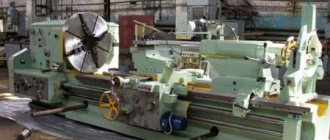
Hanging machine
The overhead roughing and grinding machine is used for processing medium and large sized metal castings. A special feature of these machines is that they are suspended, which makes it possible to rotate the massive structure in a vertical plane around its axis, as well as lift and lower it without applying significant effort.
Suspended machines are distinguished by the high power of built-in electrical units, as well as the large dimensions of the abrasive wheel. Of course, with such a “set” the labor productivity of the master is quite high.
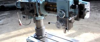
Special machines
This category of grinding and grinding machines includes a variety of automatic and semi-automatic units. All of them are involved in the casting processing process. Moreover, such devices are used mainly in mass production.
In special machines, most of the work is done automatically. The craftsman only needs to install the rough casting, and then remove the finished processed product.
Today, the grinding equipment market is saturated with a variety of equipment models. We will dwell in detail on the 3M636 roughing and grinding machine - one of the most popular units in the post-Soviet space.
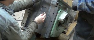
Standard device structure
The 3M636 grinding machine has several main components that work harmoniously with each other. The design of a roughing and grinding machine is not complicated.
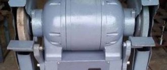
Head with two-speed electric motor. Thanks to it, the movement of abrasive wheels is ensured. The shaft is housed in a housing with two covers. Its ends are equipped with bearing units, which simultaneously support the spindle.
Spindle supports - the presented unit ensures the reliability of the equipment and the accuracy of rotation of the wheels. The supports contain seals.
Cooling unit - the operation of the electric motor is accompanied by the release of a large amount of heat, which can lead to breakdown. Therefore, the device must be cooled during operation. This is accomplished due to air flows located in the cavity of the housing and inside the frame. They circulate constantly, they have no obstacles.
Head covers - protective covers are attached to them. Additionally, it is allowed to fix devices for polishing workpieces on them.
Grinding machine head covers
Bed - most often it is made of cast iron. Inside the frame there is a cabinet in which all electrical equipment is hidden. In the front part there is a window that gives access to all internal components of the equipment. During operation, it is securely closed with a lid.
Transparent protective screens. They protect against metal dust and make work more convenient. A lamp is adopted as an additional device.
Replacing the grinding wheels is quick, because to do this you just need to fold back the side of the casing.
The design of the device is quite simple, so some craftsmen are able to build the device themselves. However, in the household there is no need for a stationary option, since at home you will not have to process hundreds of workpieces every day.
Model features
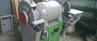
This tool is designed for cleaning and roughing castings in a production workshop. Thanks to its worthy performance characteristics, it has gained popularity in the market and has become the standard of reliability and performance.
In terms of accuracy class, this unit complies with the “H” standard, which means that the equipment is excellent for finishing work. This machine is equipped with two 600mm 75mm wide grinding wheels, which are driven by a powerful 7kW power motor. The rotation speed of grinding wheels ranges from 955-1425 rpm. In this case, the distance between the centers of the circles is 1025 millimeters.
The 3M636 roughing and grinding machine is capable of processing fairly large products. The maximum workpiece weight reaches 30 kg, which is enough to perform most tasks encountered in a foundry. The device is equipped with a small desktop 110x200 mm. At the same time, the dimensions of the machine itself are 1275x750x1350 millimeters, and the weight is 860 kg. Of course, with such parameters, transporting equipment from one workshop to another will cause a lot of trouble, which must be taken into account when purchasing.
Results
Nowadays, a craftsman should not have any problems choosing a suitable roughing and grinding machine. The market offers a wide range of different special, stationary or suspended units. Those who are limited by budget can be advised to pay attention to used Soviet equipment, such as the 3M636 model. If you are interested in more innovative machine tools, it makes sense to choose among European and Asian machines, which are superior to domestic engineering solutions in many respects.
Technical characteristics of 3M636 equipment
The 3M363 grinding machine is a domestic device used for professional metal processing. It has the following technical characteristics:
| Options | Indicators |
| Accuracy class | N (suitable for finishing work) |
| Grinding wheel dimensions (diameter) | 60 cm |
| Abrasive tool width | 7.5 cm |
| Number of grinding wheels | 2 |
| Distance between circle centers | 102.5 cm |
| Distance from the floor to the middle of the abrasive element | 85 cm |
| Maximum workpiece weight | 30 kg |
| Abrasive wheel rotation speed | 955–1425 rpm |
| Table dimensions | 11×20 cm |
| Main drive power | 7 kW |
| Machine dimensions | 127.5×75×135 cm |
| Unit weight | 860 kg |
The cost of the device is about 45 thousand rubles. But this price can vary greatly depending on the degree of wear and tear of the device.