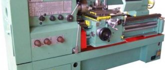
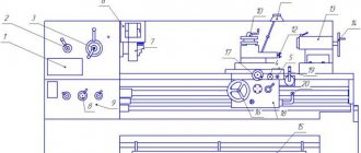
The main movement or cutting speed.
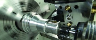
If we look at the figure given above, we will see that the main movement when turning bodies of rotation on a lathe is performed by the workpiece. It can rotate both clockwise and counterclockwise. Basically, as we see, the rotation is directed towards the cutter, since this ensures the cutting of the surface layer from the workpiece and the formation of chips.
p, blockquote 5,0,1,0,0 –>
The rotation of the workpiece is imparted by the lathe spindle and the spindle speed range (n) is quite large and can be adjusted depending on the diameter of the part, its material and the cutting tool used. When turning, these are mainly turning cutters of various types and purposes.
p, blockquote 6,0,0,0,0 –>
The cutting speed during turning is calculated by the formula:
p, blockquote 7,0,0,0,0 –>
p, blockquote 8,0,0,0,0 –>
p, blockquote 9,0,0,0,0 –>
V is the most important movement called cutting speed.
p, blockquote 10,1,0,0,0 –>
P is a constant that equals 3.14
p, blockquote 11,0,0,0,0 –>
D is the diameter of the workpiece (workpiece).
p, blockquote 12,0,0,0,0 –>
n is the number of revolutions of the machine spindle and the part clamped in it.
p, blockquote 13,0,0,0,0 –>
Features of setting up lathes
Home » Articles » Professionally about metalworking » LathesWe recommend purchasing:
Installations for automatic welding of longitudinal seams of shells - in stock!
High performance, convenience, ease of operation and reliability in operation.
Welding screens and protective curtains are in stock!
Radiation protection when welding and cutting. Big choice. Delivery throughout Russia!
Before you begin setting up the lathe, you must prepare it for work in accordance with the instructions. Before starting work, the turner must make sure that the machine carries out all commands and that the movements of the support slide (manually and automatically) are carried out smoothly, without jumps, jerking or jamming. First, you need to check that the chuck is securely fastened to the machine spindle, then at idle speed, check that the machine is following commands to start and stop the electric motor, turn the spindle rotation on and off, and turn on and off the mechanical feeds of the support.
After making sure that the machine is in good working order, we begin setting it up.
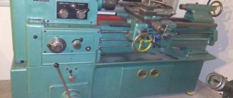
Let's look at the setup using the example of the most universal lathe of the lathe group - a screw-cutting lathe with manual control.
Setting cutting modes
consists of kinematic preparation of the machine for processing the workpiece in accordance with the selected or specified cutting mode. To do this, adjust the kinematic chains of the machine, setting the speed controls of the main movement and feed to the proper positions. Often, the required gear ratios of the adjusted chains are pre-calculated, then these ratios are established using the gearbox and feedbox handles, switching the rotation speed of the adjustable electric motor, installing the appropriate gears, replaceable cams, copiers, etc.
Setting the speed chain of modern screw-cutting lathes does not require any calculations and consists of switching the gearbox handles to positions corresponding to the specified spindle speed. To reduce switching time, machines have tables indicating which position of the handles corresponds to a certain speed value. With stepless control, the spindle rotation speed is indicated by a dial gauge.
The feed movement during turning is communicated by the running roller to the support carriage or its transverse slide. The required feed per spindle revolution is set by switching the handles without any calculations. To facilitate the switching process, the values of possible feeds are pre-calculated and presented in the form of tables given in the machine passport.
When cutting threads, both tuning elements are used - the feed box and the guitar of replacement wheels, which are rebuilt only when the type of threads being cut changes. The replacement wheels required for this are supplied with the machine. Switching the gear banks in the feed box and changing the guitar gears ensures the machine is set up to cut most standard threads. The list of standard threads is given in the passports of the corresponding models of lathes.
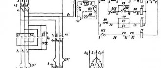
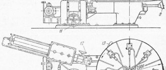
The screw-cutting chain of a screw-cutting lathe is shown schematically in Fig. 9.1. In some machine models, the feed chain may also have gears with a constant total gear ratio (not shown in the figure).
The adjustment elements of the screw-cutting chain are calculated and adjusted in such a way that the longitudinal movement of the caliper per one revolution of the spindle exactly corresponds to the pitch (When cutting multi-start threads, the chain is adjusted to the thread stroke, which is equal to the product of the thread pitch and the number of its starts) P of the thread being cut.
Total gear ratio of the specified screw chain
i'=i'ri'ki'у.ш,
where i'r,i'k and i'у.ш are the gear ratios, respectively, of the replacement gears, feed box and pitch increasing link.
In a specific example, the equation for the kinematic balance of a screw-cutting chain will be written as follows:
1 rev. sp. x i'Pх.в = Р.
To set up the machine, use the following dependency:
i' = Р/Рх.в
The pitch of the cut thread P and the pitch of the lead screw with the value Px.v must be indicated in the same units of measurement.
Installation and fastening of cutting tools on machines
are produced using a variety of devices (holders, mandrels, cutting blocks), which are related to auxiliary tools and in most cases are normalized.
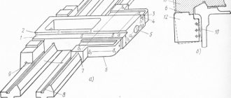
The next adjustment element is the selection and installation of the cutter in the tool holder along the height of the axis of the machine centers (Fig. 9.2). To do this, the tool holder is brought to the center of the tailstock, the top of the cutter head is set so that the overhang of the cutter does not exceed 1...1.5 times the height of its holder, the relative position of the top of the cutter head and the center of the machine is determined and their height is aligned by introducing shims under the cutter holder. The shims must have parallel and well-finished surfaces, and their length and width must not extend beyond the supporting surface of the tool holder. The number of pads should be no more than two.
Clamping fixtures
. Depending on how the workpiece should be installed and secured on the machine - in the centers, in the chuck, etc. - fixtures are selected.
For example, when installing a three-jaw self-centering chuck on a machine spindle, first wipe the threads or the tapered end and the tapered bore of the spindle with a cleaning material lightly moistened with kerosene. Then clean the internal threads or the conical hole of the adapter flange of the cartridge. A guide mandrel is inserted into the conical hole of the spindle with a sharp movement (Fig. 9.3, a); take the cartridge with both hands (Fig. 9.3, b) and carefully put it on the guide mandrel. Next, moving the chuck to the left and rotating it, the first threads of the spindle and chuck threads are aligned.
Then, supporting the cartridge with your left hand from below and simultaneously rotating it with your right hand, turn the cartridge until it stops. Using a key inserted into one of the square holes of the cartridge, pull it slightly towards you and sharply (with effort) turn it away from you until it stops (Fig. 9.3, c). To avoid self-unscrewing of the cartridge, the teeth of the locking blocks are inserted into the grooves of the spindle and firmly secured with screws; remove the guide mandrel by pushing it (with a light blow) with a brass rod through the hole in the spindle.
To install a workpiece in a three-jaw self-centering chuck, with your left hand, open the jaws of the chuck with a wrench (Fig. 9.3, d) so that the workpiece passes between the jaws; With your right hand, insert the workpiece between the jaws and first clamp it with your left hand, and then, rotating the key with both hands, finally secure the workpiece in the chuck.
If the processing is carried out in the centers, then to remove the chuck (Fig. 9.3, d), the chuck jaws are first moved apart and the mandrel is secured in the spindle hole; then they remove the locking blocks and, having inserted the key into the chuck socket, sharply turn the chuck toward themselves, and then, supporting the chuck with their left hand and intercepting it with their right, carefully screw the chuck onto the mandrel and remove it from the machine.
After removing the mandrel, carefully wipe the tapered bore of the spindle and the tapered shank of the center. Then, with your right hand, insert the center (shank) into the spindle hole and with a sharp movement insert it until it stops (Fig. 9.4, a). Turn on the spindle rotation and check the center for radial runout. If the center rotates with beating, then it is knocked out with a brass rod and reinserted into the spindle hole, rotated 30...45° around the axis. Then, with your left hand, insert the center into the tailstock quill. To check the alignment of the centers, the tailstock is moved to the left so that the distance between the tops of the centers is no more than 0.5 mm; fix the quill and check (by eye) the coincidence of the vertices in the horizontal plane. If the tops of the centers do not coincide, then their alignment is achieved by shifting the tailstock. After this, the drive chuck is installed (Fig. 9.4, b), using the same techniques as when installing a three-jaw chuck.
Characteristics of cutting conditions
The necessary technological parameters used in metal turning have their origin in the theory of cutting. Its main provisions are used by designers when designing cutting tools, metal-cutting machines and devices.
The required turning processing conditions can be obtained in two ways. In the first case, modes are assigned using tabular data. Data were recorded over a long period of time at different stages of processing with different tools.
Read also: Btb12 800cw how to check with a tester
In the second case, cutting conditions are calculated using empirical formulas. This method is called the analytical method. It is believed that the analytical method gives more accurate results in contrast to the assigned parameters.
Today, software developers offer many programs for calculating processing modes. It is enough to enter known data into the fields and the program will independently perform the calculations and display the result. This greatly simplifies the work and reduces its duration.
To manufacture a part with the specified dimensions and the required surface finish, a drawing is required. On its basis, a technological processing process is developed with the selection of the necessary equipment and tools.
Who does the adjustment
Setting up a CNC machine for processing is a complex task, which is carried out by qualified employees with technical training.
To successfully configure machine equipment, a control panel operator requires:
- professional knowledge of instrument design;
- ability to operate the device in different modes;
- ability to use technological equipment and other tools of a milling machine.
The responsibilities of the adjuster include programming and launching control systems, as well as checking the electronics and mechanics of the configured devices during operation. He must not only have theoretical knowledge of how to set up the device, but also have practical experience.
People with higher education in the field of:
- mechanical engineering;
- programming;
- electronics and computer technology.
Installers periodically need to undergo advanced training. This condition is required in connection with the periodic updating of machine-tool turning instruments, their modernization, as well as the release of new models.
Turning tools: classification
The accuracy of the resulting dimensions and processing productivity largely depend on the quality and reliability of turning tools. They must provide:
- obtaining the required form;
- dimensions;
- surface quality;
- the greatest productivity with minimal power, and therefore energy costs;
- manufacturability in manufacturing;
- possibility of restoring cutting properties;
- minimal consumption of expensive tool materials.
Turning cutters can be classified according to the processing method:
- checkpoints;
- pruning;
- cutting;
- slotted;
- fillets;
- threaded;
- shaped;
- boring
Based on the material of the cutting part there are:
- instrumental;
- high-speed;
- carbide:
- single-carbide (tungsten);
- two-carbide (titanium-tungsten);
- tricarbide (titanium tantalum tungsten);
- mineral ceramic;
- diamonds.
According to their design, turning tools are:
The choice of the type of turning cutter depends on the type of surface being processed (external, internal), the hardness of the workpiece material, the type of processing (roughing, semi-finishing, finishing), geometric parameters and the material of the cutting part and holder.
Setup diagram
The setup is carried out step by step in several stages. The sequence of steps must not be changed, otherwise the task will be completed incorrectly. There are six main setup stages:
- installation of equipment in a fixed position;
- installation of devices and working mechanisms;
- performing dimensional adjustments;
- input of control program;
- processing of a test piece;
- assessing the performance of the control program and making corrections.
It should be borne in mind that even an experienced operator cannot adjust metal-cutting devices without the need to make changes. This process is called adjustment. It represents additional adjustment in order to improve the quality of processing. If the machine was set up by a professional, he will definitely carry out adjustments and look at the errors in detail.
Input and output of control programs
Input and output of a control program is one of the simplest actions when working with a CNC machine. To perform this task, you must connect the milling tool to the control device. It can be:
- desktop computer;
- control terminal;
- laptop.
If you are using a computer or laptop, you must first install the machine program on it. These actions are performed by pressing the corresponding keys. They may also be signed in English. Additionally, after selecting a task, you must press the “execute” button. Operations can only be performed when the milling machine is switched off.
Determination of workpiece zero
This value is determined after the milling machines are linked. It will indicate the surface area of the workpiece from which processing will begin. In most cases, the end part of the part is used. It has a physical surface that the tool can touch. If it does not reach the workpiece, you must select another zone. The machine will not move the cutter to the desired location automatically, so the operator must do this.
Important! You cannot start processing a part with idle movement.
To determine this value, two functions are provided in the numerical control system:
- the first is designed for one-time processing, and after turning off the machine’s CNC does not retain the value of zero;
- the second is intended for serial processing, and ensures that data is saved after the device is turned off.
Automatic setup
The automatic mode assumes autonomous movement of the tool and control over it frame by frame. If you are milling continuously, you do not need to move the workpiece yourself, but you will need to watch for sounds. At the slightest change in the standard sound, you should press the power button. To do this, it is recommended to keep your hand on the power button when operating it. Otherwise, the workpiece will be damaged and the machine may break down.
The program does not have to be started from the very beginning. But it must begin with the tool change point. Most control programs do not have a restart function. The launch is performed on the computer or controller after selecting the desired frame.