Information about the manufacturer of the screw-cutting lathe 16B16F3
The manufacturer of the 16B16F3 universal lathe is the Srednevolzhsky Machine Tool Plant SVSZ , founded in 1876.
The production of metal-cutting machines at the Srednevolzhsky Machine Tool Plant first began at the end of January 1926. The first machine produced at the enterprise was a screw-cutting lathe with a stepped pulley, model TV-155V.
In 1934, the plant created an original screw-cutting lathe, model SP-162 , with 8 speeds and spindle revolutions per minute from 24 to 482. For the first time, an individual electric motor with a power of 1.5 kW was installed on the machine.
During the war years, the plant mastered the production of a screw-cutting lathe 1615
and soon upgraded it, bringing the spindle speed to 1000 rpm.
In 1949, the machine was put into mass production 1616
, in the sixties the models were
1B616 and 1A616
, and from the beginning of the seventies the production of the
16B16 .
Since the 90s of the last century, the SVSZ company has been producing lathes under the SAMAT .
Machine tools manufactured by the Srednevolzhsky Machine Tool Plant, SVSZ, Samara
- 1A616
universal screw-cutting lathe, Ø 320 - 1A616k
screw-cutting lathe with automatic transmission, Ø 320 - 1A616P
high-precision screw-cutting lathe, Ø 320 - 1B811
turning and backing machine, Ø 250 - 1E811
turning and backing machine, Ø 250 - 1P611
universal screw-cutting lathe, Ø 250 - 16B16
universal screw-cutting lathe, 320 - 16B16A
especially high precision screw-cutting lathe, Ø 320 - 16B16KA
especially high precision screw-cutting lathe with automatic transmission, Ø 320 - 16B16P
high-precision screw-cutting lathe, Ø 320 - 16B16KP
high-precision screw-cutting lathe with automatic transmission, Ø 320 - 16B16F3
chuck center lathe with CNC, Ø 320 - 16B16T1
CNC lathe, Ø 320 - 16D16AF1
especially high precision screw-cutting lathe with digital display, Ø 320 - 561
thread milling machine, Ø 400 x 700 - 1615
universal screw-cutting lathe, Ø 320 - 1616
universal screw-cutting lathe, Ø 320 - 1716PF3
CNC lathe, Ø 320 - 5350A
semi-automatic slot milling machine, Ø 150 - Samat 400
high-precision screw-cutting lathe, Ø 400 - Craftsman
table lathe, Ø 175
Machine 16B16P. Screw-cutting lathe. Manual. Electrical equipment
This operating manual for electrical equipment “Screw-cutting lathe 16B16P” contains information necessary both for the maintenance personnel of this machine and for the employee directly involved in working on this machine. This manual is an electronic version in PDF format of the original paper version. This documentation contains the Manual (instructions) for operating the electrical equipment of a screw-cutting lathe model 16B16P.
CONTENT
- General information
- Description of work
- Protection and blocking
- Initial launch
- Installation and operating instructions
- Recommended lubricants for rolling bearings of electric motors
- Safety instructions
- Applications. Electrical diagram of the machine
download the operating manual for the electrical equipment of the screw-cutting lathe 16B16P in good quality from the link below.
16B16F3 Chuck-center lathe with CNC. Purpose, scope
The CNC machine 16B16F3 was designed in the early 70s on the basis of the universal machine 16B16
and replaced in production the then outdated CNC lathe 16A16F3.
In 1978, the 16B16F3 machine was replaced by a more advanced model - 16B16T1 (Samat 135NC)
.
The lathe with numerical control 16B16F3 is designed for turning in the chuck or centers of various bodies of rotation with grooves, chamfers and surfaces with a curved generatrix in one or several passes in a closed automatic cycle; used in small-scale and mass production.
The technological capabilities of the 16B16F3 for centering and chuck processing are almost equivalent. The use of only four tools installed in the front tool holder for power cutting somewhat limits the technological capabilities of the machine.
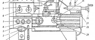
Operating principle and design features of the machine
A box-shaped bed with transverse U-shaped ribs is installed on a hollow pedestal. The caliper moves along two hardened guides of the bed, and two other guides serve to move the tailstock.
The drive of the main movement of the 16B16F3 consists of a two-speed asynchronous flange electric motor A02-52-8/4, from the shaft of which the movement is transmitted by a flat-toothed belt to the automatic gearbox (AKS) AKS209-6.3.
The spindle of the 16B16F3 receives rotation from the AKS through a flat-toothed belt drive with kinematic engagement directly or through a switch mounted in the spindle head, 17 steps of different spindle rotation speeds. Automatic switching of spindle speeds is possible in two ranges, determined by turning on the spindle directly or through search.
The machine is equipped with a threading sensor installed on the left end of the spindle head.
The drive of the longitudinal and transverse feeds is an electro-hydraulic stepper with a backlash-free ball drive screw-nut (with a split wheel to eliminate gear play). The drive of longitudinal movements has a reduction gear transmission; the backlash in the meshing is selected by bringing the gear axes closer together.
The transverse drive is similar to the longitudinal feed drive and includes an electro-hydraulic motor. Only instead of a cylindrical gear a worm pair is used.
The four-position tool holder is mounted on the transverse slide, in its front part. In the automatic operating cycle of the machine, it is controlled by the program and ensures that each of the four tools sequentially returns to their original working position. The rotation and clamping of the tool holder is carried out by a hydraulic cylinder attached to the transverse slide. Tools are installed in tool blocks, in which the base mounting surface is made in the form of a spur gear. This design makes it possible to install cutters for external machining and boring cutters into identical cutting blocks.
The nut of the ball pair of longitudinal movements of the caliper is mounted in an apron bracket attached to the carriage in front, the screw is protected by an accordion and a shield:
A double pump, driven into rotation from the first shaft of the automatic gearbox, provides centralized lubrication of the automatic transmission system, longitudinal feed drive, spindle head, rolling screw pairs and caliper guides.
The machine is equipped with a hydraulic tailstock with a manual valve spool; a pedal-controlled workpiece clamping hydraulic cylinder is available for an additional fee.
Coolant from a reservoir located on the right side of the cabinet is supplied to the quick-change cutter blocks of the tool holder in the working position.
The device with a transparent screen reliably covers the workplace from chips and coolant.
Lighting is luminescent.
By special order, the machine can be equipped with an optical device for installing cutters outside the machine, made on the basis of the BV-2011 device.
The machine is equipped with a CNC device type EM-907 , which is designed to control lathes operating with a stepper electro-hydraulic drive. Subsequently, the machine was equipped with an N22-1M .
Machine accuracy class N according to GOST 8-77.
The developer and manufacturer of the machine is the Srednevolzhsky Machine Tool Plant.
Several modifications of the machine: 16B16F3-21 was produced by the Yerevan Machine Tool Plant named after. Dzerzhinsky (Yerevan Machine Tool Production Association).
Model features
The machine has a number of features:
- the gearbox of the device is characterized by a long service life, which is ensured through the use of a V-belt system;
- the apron of the machine equipment is equipped with a handle with which the spindle rotation speed is controlled;
- the machine support and longitudinal slide are capable of moving rapidly longitudinally and transversely;
- the headstock is equipped with two gearboxes with different gear ratios;
- the device is equipped with a specially designed tool holder, which allows the operator to quickly remove the working tool from it when cutting a part;
- the equipment has been assigned accuracy category “N”;
- the unit is capable of operating in several modes, which is ensured by the use of a thyristor-type electric drive;
- There is a handle on the apron of the machine that controls the movements of the longitudinal slide and caliper at an accelerated pace.
Machine apron
All operations performed on a screw-cutting lathe are characterized by precision and high cleanliness of the thread. This is due to the fact that all the basic parts on it are of high precision, the spindle supports are equipped with high precision bearings.
All machine elements are carefully balanced. The device is characterized by stepless adjustment of cutting speed in various ranges.
The device is marked “K”, which means it contains a copy mechanism. The marking “P” indicates the high accuracy of processing products with a machine of this type.
The turning-screw-cutting electrical unit has in its design:
- a device that blocks feeds in 2 directions;
- longitudinal switching stops;
- a system that protects the device from overloads.
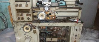
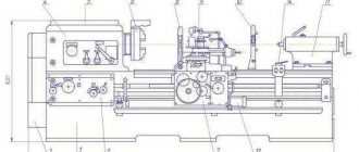
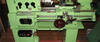
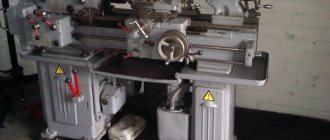
16B16F3 General view of the lathe
Photo of a CNC lathe 16B16F3
Operator's console CNC N22-1M lathe 16B16F3
CNC correction panel N22-1M for lathe 16B16F3
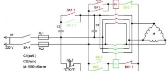
Scheme of the machine 16B16P. Screw-cutting lathe. Electrical principle
Below is a sketch of the electrical circuit diagram of the 16B16P lathe
You can download a free electrical diagram of the 16B16P screw-cutting lathe in good quality from the link above. It is contained in the Electrical Manual
Technical characteristics of the machine 16B16F3
| Parameter name | 16B16T1 | 16B16F3 |
| Basic machine parameters | ||
| Accuracy class according to GOST 8-82 | P | N |
| The largest diameter of the workpiece above the bed, mm | 320 | 320 |
| The largest diameter of the workpiece above the support, mm | 125 | 160 |
| Maximum length of the workpiece, mm | 750 | 710 |
| Cutter height, mm | 25 | 25 |
| Number of tools in the tool holder | 4 | 4 |
| Spindle | ||
| Number of spindle speeds | 18 | 17 |
| Number of stages of automatically switched spindle speeds | 12 | |
| Spindle hole diameter, mm | 37 | |
| The largest diameter of the rod passing through the hole in the spindle, mm | 36 | 34 |
| Range of spindle speeds switched according to the program, rpm | 40..500, 160..2000 | 45..560, 140..1800 |
| Spindle speed range, manually set, rpm | 40..2000 | 45..1800 |
| Headstock spindle center according to GOST 13214-67 | Morse 5 | Morse 5 |
| Spindle end according to GOST 12593-72 | 6K | 6K |
| Maximum torque on the spindle, Nm | 350 | |
| Maximum drilling diameter for steel/cast iron, mm | ||
| Submissions | ||
| Maximum longitudinal movement of the caliper, mm | 700 | 700 |
| Discretion of longitudinal/transverse movement of the caliper per step, mm | 0,01/ 0,005 | 0,01/ 0,005 |
| Maximum transverse movement of the caliper, mm | 210 | 240 |
| Range of longitudinal feed speeds, mm/min | 2..1200 | 1..1200 |
| Transverse feed speed range, mm/min | 1..1200 | 1..600 |
| Speed of fast longitudinal/transverse strokes, m/min | 6/ 5 | 4,8/ 2,4 |
| Limits of pitches of cut cylindrical threads, mm | 0,05..40,95 | 0,2..10 |
| Positioning accuracy along the X axis, mm | 0,02 | |
| Positioning accuracy along the Z axis, mm | 0,035 | |
| Standard deviation from the specified movement along the X axis, mm | 0,0025 | |
| Standard deviation from the specified movement along the Z axis, mm | 0,006 | |
| Machining accuracy in a batch of 5 parts. (span tolerance) in diameter (Ø = 84 mm), mm | 0,025 | |
| Machining accuracy in a batch of 5 parts. (span tolerance) along length (L = 30 mm), mm | 0,032 | |
| Maximum cutting force, N | 6000 | |
| Tailstock | ||
| Tailstock quill stroke, mm | 120 | |
| Tailstock quill center according to GOST 13214-67 | Morse 3 | |
| CNC system parameters | ||
| CNC system designation | Electronics NTs-31 NC-201(M) | N22-1M |
| Reference system | In absolute value In increments | In increments |
| Number of coordinates/simultaneously controlled coordinates | 2/ 2 | 2/ 2 |
| Resolution in the longitudinal direction (discreteness of the task along the Z axis), mm | 0,01 | 0,01 |
| Resolution in the transverse direction (discreteness of the task along the X axis), mm | 0,005 | 0,005 |
| Feedback sensor type | ||
| Threading sensor type | IGR | |
| Electrical equipment. Drive unit | ||
| Number of electric motors on the machine | 7 | |
| Main motion drive electric motor, kW (rpm) | 4,2/ 7,1 (720/ 1440) | 3,8/ 6,3 (750/ 1500) |
| Electric motor for longitudinal feed drive, N*m | 100 | |
| Cross feed drive electric motor, N*m | 70 | |
| Turret head electric motor, kW | 0,18 | — |
| Quill drive electric motor, kW | 0,18 | — |
| Electric motor of hydraulic station, kW | ||
| Lubrication station electric motor, kW | 0,09 | |
| Cooling pump electric motor, kW | 0,18 | |
| Total power of electric motors, kW | ||
| Total power consumption of the machine, kW | 13,0 | |
| Dimensions and weight of the machine | 3100 x 1390 x 1870 | 3065 x 2395 x 1860 |
| Weight of CNC machine, kg | 2860 | 2500 |
- Panov F.S., Travin A.I. Work on lathes with numerical control, 1984. P. 76
- Acherkan N.S. Metal-cutting machines, Volume 1, 1965
- Batov V.P. Lathes, 1978
- Beletsky D.G. Handbook of a universal turner, 1987
- Denezhny P.M., Stiskin G.M., Thor I.E. Turning, 1972. (1k62)
- Denezhny P.M., Stiskin G.M., Thor I.E. Turning, 1979. (16k20)
- Modzelevsky A. A., Muschinkin A. A., Kedrov S. S., Sobol A. M., Zavgorodniy Yu. P., Lathes, 1973
- Pikus M.Yu. A mechanic's guide to machine repair, 1987
- Skhirtladze A.G., Novikov V.Yu. Technological equipment for machine-building industries, 1980
- Tepinkichiev V.K. Metal cutting machines, 1973
- Chernov N.N. Metal cutting machines, 1988
Bibliography:
Related Links. Additional Information
- Classification and main characteristics of turning
- Selecting the right metalworking machine
- Graphic signs for lathes
- Methodology for checking and testing screw-cutting lathes for accuracy
- Manufacturers of lathes
- Manufacturers of metal-cutting machines
- Directory of lathes
- Generations of CNC systems. Terms and concepts of CNC systems
- Russian manufacturers of modern CNC systems
- Review of Russian-made CNC systems
- Recommendations for choosing CNC devices
- Problems with modernized CNC machines: tips and tricks from professionals
- Requirements for ensuring stability and safety of machine control systems
Home About the company News Articles Price list Contacts Reference information Interesting video KPO woodworking machines Manufacturers
Description
This machine is a fairly deep modification of the device from the 16b16 line. The period of the most active development and production of such machines fell in the 70s of the twentieth century. The main difference between the 16b16kp machine and its counterparts was the automated gearbox. This factor significantly increased the convenience of the device and its operating efficiency.
The machine has other important features that set it apart from other similar mechanisms:
- The working equipment belongs to the “N” accuracy class.
- The machine has a fairly ergonomic shape and relatively small dimensions.
- The tool holder of the device is designed in such a way that while creating a thread, the operator can quickly remove the cutting tool from the workpiece.
- In the front headstock of the machine there are two gears with different gear ratios (1:4 and 1:16).
- The longitudinal slide moves in any direction in a forced mode.
- After processing on this machine, the workpieces have excellent surface cleanliness. This result was achieved thanks to the installation of bearings with high precision characteristics and due to the high-quality assembly of other working components of the machine. In addition, the design of the device allows the operator to adjust the speed of cutting parts.
- The service life of the feed box is achieved through the use of a special kinematic scheme. At high processing speeds, information from the working surfaces is transmitted to the feed box using a V-belt system, which has a positive effect on the operating life of the device.
- The operator can quickly select the required processing mode for the part thanks to the presence of a special electric drive.
- The operator controls the intensity of spindle rotation with a handle on the apron of the machine.
Device markings “K” and “P” indicate the presence of a copier and an increased level of accuracy, respectively. In total, there are about twenty different modifications of machines from this line. Unlike most other models, this machine is designed for more filigree turning, so it is not recommended to be used for “rough work”.