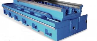
Repair by scraping
Scraping of guides or scraping followed by lapping remains the most effective way to restore their geometric and technical accuracy. And now this method is often used, demonstrating excellent results in machine bed repair for many decades. First of all, it is necessary to examine the condition of the guides and determine the degree of their wear. The place where the wear is minimal is taken as the base level, and the measurement data is entered into a table, on the basis of which repairs will be made. In a lathe, the base surface is most often taken to be the location of the tailstock, which practically does not wear out during operation of the equipment. The method includes the following steps:
- installation of the machine bed on a rigid base (repair stand), the longitudinal and transverse position of the bed should be adjusted exactly in the horizontal plane using wedges, shoes or using jacks;
- after completion of the preparatory work, rough (preliminary) scraping is performed with a working scraper width of 20-25 mm, while maintaining a length of strokes on the surface of more than 10 mm and achieving 4-6 spots when checking paint in 25x25 mm squares. This achieves the breakdown of large spots into smaller ones;
- semi-finish scraping is performed with a 12-16 mm scraper, stroke length 5-10 mm until 8-15 spots per square are achieved;
- finishing (finishing) scraping is carried out with a scraper 5-10 mm wide and strokes 3-5 mm long to achieve 20-25 spots per square.
[Show slideshow]
Since the guides of the lathe bed are quite long, processing is carried out along the beacons, dividing the total length into sections. The first beacon is always the place of maximum production. At a distance less than the length of the straight edge from the first beacon, a second beacon is scraped, located in the same plane as the first. Then the entire surface between the beacons is scraped, followed by moving to the adjacent area. Periodically, apply a ruler with paint to assess the condition of the guides and the quality of work.
Watch the video of rough scraping
Non-hardened parts of lathe guides are subjected to this treatment; the method guarantees the achievement of high surface accuracy (0.002 mm per 1000 mm length). The tiny holes formed after scraping are able to hold the lubricant well and distribute it evenly. The quality of scraping depends entirely on the professionalism of the worker.
Eliminating scoring on guides using polymer materials
- home
- Articles
- Eliminating burrs on guides
2
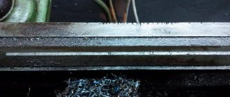
Another common defect that occurs during the operation of grinding machines is the appearance of scoring. The cause of this type of defect can be, for example, loss of lubricant during operation. Similar damage was found on the bed guides of the roll grinding machine mod. LUX5-05. A section 7200 mm long was damaged. Across the entire width of the guides, from 8 to 12 burrs up to 0.8 mm deep were recorded.
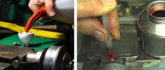
To apply the polymer material, the notches were pre-prepared: the V-shaped notch in cross-section was given a U-shape using a disk cutter. Surface preparation, filling of burrs with Moglais FL/P and formation of the working surface were carried out similarly to the operations described in the first case.
Similar damage was eliminated on the carriage guides using the multimetal-steel material (Diamant, Germany). The described types of repairs did not require dismantling the machine frame and were completed in a short time.
One of the most complex repairs carried out in recent years was the repair of a horizontal boring machine mod. 2A656F11. The machine received damage in the form of multiple scratches in the lower part of the bed guides at a length of 1500 mm and similar damage on the carriage guides. It was decided to restore the guides using polymer material. Another option - grinding six planes of guides over a length of 4000 mm - was not possible in the conditions of a metallurgical plant. Sending the machine to the manufacturing plant was unacceptable due to the high cost and the impossibility of removing the machine from the production process.
The initial stage was to restore the bed guides. The damaged areas were milled to a depth of 2.0 mm. The formation of the plane of the bed guides, installed horizontally, was carried out using the “multi-metal-steel” material and polished rulers. Particular attention was paid to ensuring contact of the rulers with the base surfaces after applying the material. For this purpose, specially designed traverses and screw clamps were used (for horizontal planes of the frame), as well as powerful clamps (for vertical planes of the frame).
The guide carriages were prepared for the next step. The milled grooves of all six guide planes (four horizontal and two lateral vertical) were degreased. The restoration was carried out using Moglais FL/P and Moglais-hart materials. Two vertical guides were restored by injecting a restoration compound with an injector into the gap between the ruler and the groove milled in the guide. The ruler was installed in advance and secured with clamps.
The final stage of forming 4 carriage guide planes was performed after applying the material to the milled grooves. The material was applied with 30% excess of the required volume. Then the bed was laid on the carriage and secured with special clamps. This operation was complicated by the uneven load on the carriage and the impossibility of installing it in a strictly horizontal position. In this regard, the carriage was mounted on a hinged device, which ensured a perfect fit. Thus, all 4 guides were formed by the bed guide planes in one installation. The required technological processing accuracy has been restored, there are no comments on the work.
Article parts: 2
Repair by grinding
It is not always possible to use planing or longitudinal milling machines for repairs due to the long length of the lathe bed. In this case, the bed guides are restored using a portable device with a grinding head, which is installed directly on the equipment bed.
Repairs can be made on site, without removing the machine from the foundation. This method ensures high repair accuracy, low surface roughness, and is also indispensable when processing hardened surfaces. This method is many times more productive than scraping, but experts still prefer finishing planing.
[Show slideshow]
Repair cost
| Type of work | Price |
| Spindle Prevention | 9,000 rub. |
| Troubleshooting clamping devices | 19,000 rub. |
| Burnout (damage) of the stator winding | 30,000 rub. |
| Replacing bearings with rotor balancing | 50,000 rub. |
| Replacing spindle sensors | 10,000 rub. |
| Maintenance | 10,000 rub. |
| Non-standard work | 10,000 rub. |
| Major renovation | 50,000 rub. |
| Modernization of machine tools | 30,000 rub. |
Our main specialization is machine repair
If your machine does not work, our specialist will arrive as soon as possible and fix it. Call and consult by phone: 8
Technologies
Thanks to the use of modern devices, we can more accurately identify faults. And we save your money on repairs
Ideas
If your machine does not break down as usual. We will send it to our technicians and they will solve any problem
Speed.
You need the machine to work as quickly as possible. Our desires coincide.
Read useful information:
Overhaul of machines
Not one unit can work forever. To restore the functionality of turning equipment, they often resort to major repairs. It is difficult to carry out this process on your own, so it is worth contacting a company that specializes in repairing these units.
Further
Self-repair of the machine shaft and care for it
In the modern world, the use of complex equipment is associated with wear and tear. In particular, the shafts of various machines are subject to enormous loads due to the large volume of work, and sometimes due to the conditions in which they are operated. The article discusses the main causes of breakdowns, as well as methods of prevention and maintenance of equipment. Questions about repairs for various damage to machine shafts are also covered.
Further
Repair of the electrical part of the machine
The slightest malfunction of the electrical part of the machine can disrupt the plant’s work schedule. It is important to be able to identify the source of the problem and eliminate it.
Further
How to set up a machine correctly
But before you start working, all the machines need to be set up. How this happens and what it means is written below in the article.
Further
Machine head repair
The headstock is an important element of the machine. If this part fails, it is very difficult to cope with the repair yourself and you have to contact specialized workshops. How to prevent breakdowns, what is important to know when doing your own repairs and how much the services of qualified craftsmen cost - all this can be learned from the article.
Further
When concluding a long-term service agreement, you receive a discount of up to 20%. Don't forget, we have a guarantee on all types of work.
- engineer - mechanic
- CNC programmer
- Service engineer
- Electrician
- Electronics engineer
- Locksmith - repairman
Video course by Viktor Leontiev “Turning” and educational videos
- 1.1. The device of a screw-cutting lathe
- 1.2. Control of a screw-cutting lathe
- 1.3. Lathe Maintenance
- The device of a screw-cutting lathe. Educational video
- Purchase, operation and repair of a TV-4 lathe. Educational video
- Design and principle of operation of a CNC lathe. Educational video
- 2.1. Operating the Three-Jaw Chuck of a Lathe
- 2.2. Installing the chuck on the machine and checking the centering accuracy
- 2.3. Boring and lapping of lathe chuck jaws
- 2.4. Restoring the lathe spindle mounting base
- 2.5. Quality control of lathe chucks
- 3.1. Measuring with calipers on a lathe
- 3.2. Micrometer measurements on a lathe
- 4.1. Concept of the cutting process on a lathe
- 4.2. Cutters for metal lathe
- 4.3. Tool steels
- 4.4. Hard alloys and materials
- 4.5. Super hard cutting materials
- 4.6. Heat generation during metal cutting
- 4.7. Cutting force and machine rigidity
- 4.8. Tool deformation and its causes
- 4.9. Rigidity of fastening parts
- 4.10. Deformation of treated surfaces
- 5.1. Installing cutters on a lathe
- 5.2. Using Limbs
- 5.3. Axial stops on a lathe
- 5.4. Working with longitudinal feed stops
- 5.4.1. Working with a universal stop
- 5.5. Cross and axial feed stops
- 6.1. Size, deviations, tolerance when processing workpieces on a lathe
- 6.2. Tolerances and fits when processing on a machine
- 7.1. Positioning of workpieces during processing on a machine
- 7.2. Bases and base sets
- 7.3. Cylinder alignment
- 8.1. Sharpening machines and wheels
- 8.1.1 Basic rules for working on grinding machines
- 8.1.2 Installing the grinding wheel
- 8.1.3 Dressing grinding wheels
- 8.1.4 Retrofitting tabletop sharpening machines
- Sharpening drills for drilling sheet material
- Sharpening turning tools on a technological plate
- Sharpening the front surfaces of turning tools
- Sharpening drills with flat back surfaces
- Sharpening taps
- Non-standard drill sharpening
- 9.1. Measuring metal temperatures based on heat and tarnish colors
- 9.2. Metal hardness measurements
- 9.3. Internal stresses in metals
Operation of a universal screw-cutting lathe
Three jaw chuck
Measuring tools
Cutting theory
Getting started on a lathe
Tolerances and landings
Practical basing of parts
Working on grinding machines
Measuring the hardness and temperatures of metals
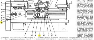
Lathe device
A classic lathe made in the USSR consists of the parts shown in the drawing:
Lathe device - front view
This figure does not show everything, only some parts, but this is enough for a basic understanding. The parts that are related to electrical are highlighted.
- 8 – handle for clutch and switching direction of spindle rotation. The important thing is that this handle acts on the zero stroke limit switch - while it is pressed, the machine will not turn on.
- 12 – Start and Stop buttons for controlling the main engine.
- 21 – non-latching button to turn on the high-speed motor (accelerated movement of the carriage).
- 24 – lighting lamp.
- 27 – direct connection ammeter, for monitoring the main motor current.
- 28 – toggle switch for turning on the engine of the coolant pump (coolant).
- 29 – power on indicator.
- 30 – power handle.