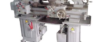
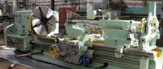
Advantages of the 1K62 model
These days, this unit is used quite widely and is considered to be very high quality equipment. The technical characteristics of the 1K62 lathe are simply excellent. The undoubted advantages of this model include:
- Versatility. The 1K62 can be used to perform any type of work, including thread cutting.
- Possibility of use for processing workpieces made of very hard hardened metal. The machine spindle is mounted on bearings of a special design, ensuring fastening rigidity.
- Greater power of the main drive and reliability of the kinematic motion scheme assembly.
- Wide range of gears and speeds.
- Cutting on the 1K62 machine can be performed with mineral-ceramic as well as carbide tools.
- Vibration resistance is one of the advantages that this heavy metal lathe has.
- High precision even when used in impact mode.
Feed movement of the machine
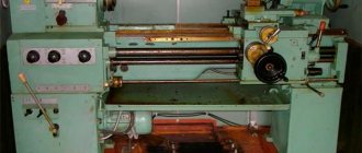
Model 1K62 belongs to frontal lathes, and therefore is used mainly for processing workpieces that are not too long and at the same time dimensional.
The design of the 1K62 lathe is practically no different from the design of any other equipment in this group. This model uses a squirrel-cage asynchronous power unit with a power of 10 kW as a drive. The speed of movement of the caliper and rotation of the spindle is controlled by two separate handles. This is one of the features of the model. In addition to the main one, the machine uses an additional motor, also asynchronous, with a power of 1 kW. This power unit ensures that the caliper moves quickly.
Thus, the feed mechanism of the 1K62 machine includes four kinematic chains:
- screw-cutting;
- cross cutting;
- slitting;
- accelerating the movement of the caliper.
Tailstock of a lathe. Construction and repair of the tailstock
The device of the tailstock of a screw-cutting lathe
The general view and layout of the tailstock of a screw-cutting lathe is shown in Fig. 33.
The tailstock serves to support the workpiece during processing in the centers and represents a second support.
When drilling, the tailstock is connected to the caliper carriage with a special clamp and receives mechanical feed from it. The drill is inserted into the quill instead of the center.
The tailstock must satisfy the following conditions:
- under no circumstances move arbitrarily
- give the correct position of the center axis
- enable quick installation along the machine axis
- provide the ability to accurately position the workpiece on both center holes of the machine
- ensure reliable direction of the spindle (quill) of the tailstock and its clamping without disturbing the position of the axis
The stability and reliable position of the tailstock axis are necessary conditions for obtaining satisfactory results when machining on centers and eliminating the possibility of accidents due to the workpiece being pulled out of the centers. This depends on how the tailstock housing is secured to the frame.
The designs of tailstocks are very diverse, but their basic concepts have much in common. Therefore, knowing the basic structure of the tailstock of any medium-sized universal lathe, you can easily understand the design of the tailstocks of other lathes.
Let's look at the design of the tailstock of a lathe. The tailstock body of this machine, like most other types of machines, consists of two parts: the body itself 1 and the base (raft, bridge) of the tailstock 2.
The raft (bridge) is scraped along the frame guides, and the body is installed on its upper surface.
The planes of contact between the body and the raft are scraped so that the axis of the tailstock coincides in height with the axis of the machine spindle and is parallel to it.
Parallelism of the axes is achieved by scraping the vertical edge of the guide bead on the raft.
Lateral alignment of the axes is achieved by moving the body along the raft using a square-head screw and nut. The body is attached to the raft and at the same time to the frame using two bolts 4 and a lining 3. Achieving coincidence of the axes of the spindles of the headstock and tailstock by scraping the supporting planes of the headstock body requires a significant investment of time. Therefore, as a rule, during a major overhaul, the coincidence of the axes of the headstock and tailstock is achieved by boring the hole for the tailstock spindle. In this case, it becomes necessary to replace the tailstock spindle, which is finally machined along the outer diameter only after boring the tailstock body.
The tailstock spindle (quill) 7 is a hollow cylinder, the front edge of which is made in the form of a Morse cone into which a center 6 or drill is inserted, and a nut 9 is inserted into the rear edge. Using this nut and a screw 8 with a flywheel 10, the spindle can move along the axis . Key 5 protects the spindle from turning. The spindle is clamped with a handle, which has right and left threads at the end for clamping nuts. When the spindle is retracted completely into the tailstock, screw 8 with its end rests against the end of center 6 and pushes it out of the spindle body. Thus, in this design, knocking the center out of the cone is very convenient.
In heavy machines, the spindle does not have a nut, the cutting is done directly on the spindle, and the flywheel bushing is a nut. It is impossible to knock out the center from the end of such a spindle. Therefore, ordinary centers are not suitable for such spindles; the centers should be threaded. A nut is screwed onto the thread, with which the center can be pressed out, or flats are made on the centers, which make it possible to turn the center with a key and thereby release it from the socket. The use of simple centers on these machines should be prohibited, since they are pressed in and can only be knocked out by hitting a sledgehammer or heating the spindle with blowtorches. This leads to damage to the spindle cone.
When processing flat cones, it is necessary to shift the center of the tailstock in the transverse direction. For this purpose, the tailstock body and the base are connected to each other by a transverse key. The transverse displacement of the headstock body relative to the base is made by screws and a nut.
Tailstock of lathe 1k62. Assembly drawing
Tailstock of a lathe. Assembly drawing. View enlarged
Tailstock of lathe 16k20. Assembly drawing
Tailstock of a lathe. Assembly drawing. View enlarged
Repair and restoration of the tailstock of a lathe
When repairing the tailstock, the accuracy of the mating surfaces of the bridge with the frame and the body, the accuracy of the body opening and the height of the centers of the front and rear stock are restored, the quill, feed screw and other parts are repaired or remanufactured.
The most labor-intensive operations are to restore the accuracy of the hole in the body for the quill and restore the height of the centers.
The hole for the quill in the body is repaired by lapping, boring, followed by finishing, and using acrylic plastics.
Laps usually repair lightly worn holes. In this case, the height of the centers is restored by placing compensation pads on the guides and a new quill is made.
When repairing by boring, the height of the centers is simultaneously restored. After boring, the hole is usually finished with laps, and the quill is made of a larger diameter.
Acrylic plastics restore both the precision of the quill fit and the height of the centers. In this case, the quill is not manufactured, but repaired.
This repair method is the most effective, since it requires 3-5 times less time and money than the first two methods.
The two options for repairing the tailstock discussed below clearly confirm the profitability of repairs using acrylic plastics, in particular styracrylic of the TSh brand.
Repair of the tailstock housing and bridge without the use of acrylic plastic
The repair sequence is as follows:
- The surface of the 9th body is scraped (Fig. 60). The number of paint prints must be at least 10 on an area of 25 X 25 mm
- The surface 10 of the bridge 8 is milled and the cover is installed with glue or screws. If the bridge protrusion is tightly coupled with the housing groove, this operation is not performed
- The surfaces of the bridge mating with the hull are scraped (along the hull). The number of spots when checking for paint is at least 10 on an area of 25 X 25 mm. The protrusion of the bridge must fit tightly into the groove of the housing (without play)
- The surfaces of the bridge are scraped along the frame guides. The number of paint prints is 10-15 on an area of 25 X 25 mm. At the same time, when scraping, the surface mating with the body is ensured to be horizontal with an accuracy of 0.05 mm per 1000 mm of length. The check is carried out using a level installed on surface 9 along and across the frame guides. The frame is installed and leveled, while the plane for attaching the feed box must be positioned strictly vertically.
- Attach the bridge to the hull
- The bead rod is secured in the spindle of the machine headstock. The axis of the bead rod at the point where the cutter is attached must be 0.05 mm higher than the normal position of the spindle axis, for which: the measuring rod of the indicator, mounted on the machine support, is brought to the upper generatrix of the bead rod (at the point where the cutter is attached) and this position is fixed; loosen the front bolts securing the headstock (the spindle axis is already aligned parallel to the frame guides), use a lever to slightly raise the front part, place 0.02-0.05 mm thick foil under the front ends of the guides and secure the headstock to the bed; bring the indicator to the upper generatrix of the bead rod and notice its new position, in which the axis of the bead rod should be located 0.05 mm above the spindle axis.
- Install the tailstock in front of the caliper carriage and apply a weight for rigidity
- Boring the hole for the quill in the tailstock body (in 2-3 passes), spindle rotation speed 250 rpm; feed 0.1 mm/min. In this case, the surface finish must be no lower than V5, taper - no more than 0.02 mm, ovality - no more than 0.01 mm.
- Grind the hole in the body using an expanding mandrel mounted in the spindle and sandpaper. Spindle rotation speed 500-800 rpm, feed 10-15 m/min. Surface finish V7, taper - no more than 0.02 mm, ovality - no more than 0.01 mm
- The hole in the body is fine-tuned using a cast iron lap. Spindle rotation speed 200-300 rpm, feed - 5-8 m/min. In this case, a surface cleanliness of V 8 is achieved, the taper should be no more than 0.01 mm, and the ovality should be no more than 0.005 mm.
- Remove the foil from under the headstock guides and secure the headstock to the bed. The tailstock is assembled with a newly manufactured and fitted quill. The movement of the quill should be smooth, without backlash. The clamp should ensure reliable fastening of the quill.
- Check the position of the quill in relation to the bed guides and the coincidence of the centers of the front and rear stock, in accordance with the technical specifications in accordance with GOST 42-56.
The considered tailstock technological process is widely used in many factories, despite its significant labor intensity.
Restoring the tailstock with acrylic plastic
Restoring the tailstock with acrylic plastic is very simple and effective, since operations on precise boring and finishing of the housing hole are eliminated and it is possible to preserve the old quill. Bridge repairs are carried out in the same way as for repairs without acrylic plastic.
The technological process of restoring the hole in the tailstock housing includes the following operations:
- The hole for the quill in the body 4 of the tailstock (Fig. 60) is bored on a boring or lathe, and a layer of metal equal to 2-3 mm is removed. The cleanliness of the processing must correspond to V 1, taper and ovality are allowed no more than 0.5 mm.
- In the spindle 2 of the headstock 1 of the machine, the axis of which is adjusted to be parallel to the bed guides, a hollow mandrel with a plug 7 is installed. The outer diameter of the cylindrical part of the mandrel corresponds to the outer diameter of the repaired quill and has a size 0.01 mm larger than the quill. The mandrel is installed eccentrically relative to the spindle axis by 0.07-0.08 mm. To do this, a gasket shaped like a truncated cone with a thickness of 0.07–0.08 mm is placed in the conical hole of the spindle before installing the mandrel. The material for the gasket is paper or foil. The shape of the gasket (truncated cone) ensures uniform runout at both ends of the mandrel.
- By rotating spindle 2, check the runout of the mandrel, which should be no more than 0.15-0.18 mm, and install the spindle so that the generatrix of the mandrel with the largest positive deviation is located above the spindle axis. This arrangement of the mandrel ensures that the difference in height between the centers of the headstock and tailstock (0.05-0.07 mm) is established in accordance with the requirements of the technical specifications.
- In the body of the tailstock 4, three holes with a diameter of 6-8 mm are drilled above the hole for the quill; holes are located in the middle and along the edges of the body
- Degrease the bore of the housing and dry for 15-20 minutes until the solvent has completely evaporated.
- A thin, even layer of soap is applied to the mandrel, the tailstock body is installed and bolted to the frame.
- The hole for the quill (the space between the mandrel and the headstock body) is sealed with rings and plasticine 6; The holes of the quill fastening devices are also sealed, and three funnels 3 and 5 are installed from plasticine above the three drilled holes.
- Prepare an acrylic solution and pour it into the middle funnel. Filling is completed when the mass of styracrylic partially fills the outer funnels
- The flooded tailstock is kept in place for at least 2 hours at a temperature of 18-20 ° C
- They move the tailstock, protect the body from plasticine and tides of plastic, make lubrication grooves, drill holes, chisel the keyway and assemble the tailstock
Tailstock quill repair
This process involves grinding the outside diameter and restoring the taper bore by installing an expansion sleeve.
The compensation sleeve (Fig. 61, a) has a cylindrical shape on the outside and a cone on the inside. The bushing is often made from case-hardened steel, with the cone hardened to HRC 58-60. The wall thickness of the bushing near the largest diameter of the cone is taken to be 2 mm or more (depending on the diameter of the quill).
The outer diameter of the bushing is made according to the bored hole of the quill with a gap of 0.05 mm, the cleanliness of the machined surface is V5-V6.
The bushing is glued into the quill and after hardening (after 24 hours), the conical hole is ground.
As an example, we give the technology for restoring the tailstock quill of a screw-cutting lathe model 1E61, which consists of two stages:
- manufacturing an expansion sleeve (Fig. 61, a)
- quill repair (Fig. 61, b)
- The sleeve is machined with technological allowances, Morse taper No. 3, for grinding the interference is 7-8 mm, not counting the allowance of 5 mm. Cement to a depth of 0.8-1.2 mm. Remove technological allowances, leaving 1 mm per side. Kalat, HRC 58-62. The outer diameter and ends are machined according to the drawing (checked on a cone mandrel).
- Bore a hole in the quill Ø30A to a length of 90 mm (check for runout with an accuracy of 0.05 mm, finish V 5). Install the bushing with epoxy glue and keep it for 24 hours at a temperature of 18-20° C. Insert plugs on both sides, center them with an accuracy of 0.02 mm, grind the quill along the top to size and trim the front end, chamfering. Grind the outer diameter to size. The lubrication groove is milled according to the sketch. The numbers are engraved according to the sketch. Remove the plugs. Then the quill is aligned with an accuracy of 0.01 mm, the Morse taper No. 3 is ground on the cork and the front end is clean.
A quill repaired using this technology has increased wear resistance of the tapered hole, and the cost of repair is significantly lower than the cost of manufacturing a new quill.
Repair of the tailstock bridge of a screw-cutting lathe 1k62
Boring the tailstock of a screw-cutting lathe
Lapping the tailstock of a screw-cutting lathe
Adjusting the tailstock of a lathe
Literature
- Borisov G. S. and Sakharov V. L. A short reference book for a shop mechanic. M., publishing house "Machine Building", 1966.
- Gelberg B. T. Factory experience in modernizing machine tools. Lenizdat, 1960.
- Gelberg B. T. and Pekelis G. D. Issues of technology and organization of equipment repair. M., Proftekhizdat, 1960.
- Gelberg B. T. and Pekelis G. D. Repair of industrial equipment. M., publishing house "Higher School", 1967.
- A unified system of scheduled preventive maintenance and rational operation of technological equipment of machine-building enterprises. M., publishing house "Machine Building", 1967.
- Klyagin V.N. Technical conditions for the repair of metal-cutting machines of normal accuracy. M., publishing house "Machine Building", 1967.
- Pekelis G.D. and Minkin A.S. Repair of metal-cutting machines. Lenizdat, 1962.
- Pekelis G. D. and Gelberg B. T. Restoration and strengthening of process equipment parts. M., publishing house "Machine Building", 1964.
- Pekelis G. D. and Gelberg B. T. Mechanization of metalwork and repair work. M.-L., publishing house "Machine Building", 1967.
- Pekelis G. D. and Gelberg B. T. Repair of metal-cutting machines and forging and pressing equipment according to standard technological processes. M., publishing house "Machine Building", 1967.
- Pekelis G. D., Gelberg B. T. and Gordin Yu. N. Centralization and specialization of equipment repair in a production association, LDNTP, 1967.
- Pronikov A. S. Calculation and design of metal-cutting machines. M., publishing house "Higher School", 1967.
- Sheingold E. M., Nechaev L. N. Technology of repair and installation of industrial equipment. M.-L., publishing house "Machine Building", 1966.
- Shchebrov V. M. Repair of machines and mechanisms. M., publishing house "Higher School", 1964.
- Yakobson M. O. Machine tool technology. M., publishing house "Machine Building", 1968.
Useful links on the topic
Catalog directory of metal-cutting machines
Passports and manuals of metal-cutting machines
Directory of woodworking machines
Buy a catalog, directory, database: Price list of information publications
Pekelis G.D., Gelberg B.T. L., "Mechanical Engineering". 1970
stanki-katalog.ru
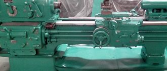
Headstock and tailstock
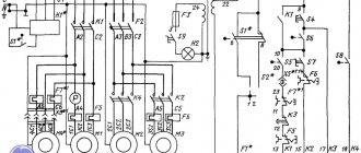
When the machine is operating, the feed from the main engine is transmitted to the driven pulley, and then, through a complex system of couplings and blocks, to the headstock with the spindle. The movement is then transmitted to the bit shaft and the feed mechanism. The rolling bearings of the assembly shafts can be lubricated either by splashing or by force. The design of the model includes a special oil pump.
The tailstock of the 1K62 unit can move along the frame guide and is equipped with a plate. The retractable quill moves using a screw pair and a flywheel. Its extension is fixed with a handle. The headstock body itself can move relative to the plate in the transverse direction. If necessary, the headstock can also be fixed to the bed. Sometimes a special tool is installed in the quill socket, designed for processing holes.
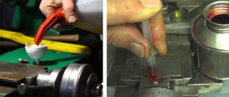
Lubrication of screw-cutting lathe 1K62
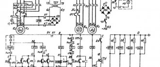
Lubrication diagram for screw-cutting lathe 1k62
The durability of machine mechanisms largely depends on timely and high-quality lubrication of interacting parts. Before lubrication and startup, the machine is thoroughly wiped.
When the machine is operating, all parts of the mechanism and headstock bearings (Fig. 4) are lubricated by an automatically operating plunger pump 2.
A plunger pump, driven by an eccentric mounted on the friction shaft, supplies oil from a reservoir located at the bottom of the headstock housing, through a plate filter to the front spindle bearing and onto a tray, from where it spreads to the necessary mechanisms of the assembly.
After turning on the machine, a thin stream of oil should appear in the inspection eye located on the top cover of the headstock, indicating normal operation of the pump. If a trickle does not appear, it is necessary to remove the upper headstock cover and, using a stop screw screwed into the drive lever, adjust the normal operation of the pump.
The oil level in the reservoir should be checked daily before starting work. If, when the machine is stopped, the oil level is below the oil indicator mark located on the left side of the headstock, it is necessary to add oil to the reservoir. When the machine is turned on, the oil level in the reservoir decreases, as some of the oil circulates in the system. This does not require additional oil filling.
When changing the oil, remove the oil drain plug located in the oil indicator.
It is recommended to change the oil immediately after turning off the machine, when all wear particles and dust are suspended and removed along with the used oil.
Before filling the housing again with oil, thoroughly rinse and clean the headstock to completely remove any settled dirt. It is unacceptable to use cleaning materials with loose fibers for cleaning.
Fresh oil should be added only after the assembly has been thoroughly dried.
The feed box is lubricated by plunger pump 3 located in the upper part of the housing. The proper operation of the pump can be monitored through the inspection eye located on the front cover of the feed box. To control the oil level, there is an oil indicator located under the sight glass.
Oil is poured into the upper part of the feedbox reservoir. The oil drain plug is located in the bottom wall of the housing.
The plunger pump 4 in the apron is mounted in the bottom cover and is driven by the eccentric of the worm gear shaft. It provides lubrication to all drive parts, bearings and guides of the caliper and carriage.
The oil supply to the caliper and carriage guides is turned on using valve 10.
It is recommended that at the beginning of the shift, set the valve to position “0” (open) and run the carriage along the frame and the lower part of the support along the carriage at high speed two or three times. After this, the tap should be returned to position “3” (closed).
If the valve remains in position “0” (open) while the machine is operating, then all the oil from the apron reservoir will be pumped out during the shift.
Oil is filled through a hole in the left wall of the apron, closed with a plug.
There are two oil drain plugs in the lower apron cover. The transverse and longitudinal feed screw of the caliper and their supports, as well as the axis of the cutting head, are lubricated with grease nipples 7, 11, 12, 13.
Lubrication of the supports of the eccentric shaft of the quill and the tailstock screw is carried out through grease fittings 5, 8, 9, 14; The bearings of the lead screw and the lead shaft are lubricated through a hole closed by plug 6.
During operation of the machine, it is necessary to monitor the operation of the oil pumps and the presence of oil in the tanks. Oil characteristics and lubrication intervals are indicated in the lubrication chart.
Model support and apron mechanism
The 1K62 metal lathe is equipped with a support, the design of which includes the following elements:
- lower slides designed for longitudinal movement along the guides;
- a transverse carriage, in the circular guides of which a rotating plate is installed under the cutting slide.
The plate can be clamped at any angle relative to the spindle. The apron mechanism is located in a housing screwed to the caliper carriage. The longitudinal movement of the caliper is ensured by a rack and pinion wheel, and the longitudinal movement by a special screw.
Technical characteristics of the 1K62 lathe: main parameters
The 1K62 machine can also be used to work with hollow conical parts. This is ensured by the possibility of shifting the workpieces in the transverse direction.
The technical characteristics of the 1K62 machine are as follows:
- height of the part above the caliper - 224 mm;
- the maximum permissible height of the workpiece above the bed is 430 mm;
- length of workpieces - 750-1500 mm;
- mass of the part fixed in the centers - 460-900 kg;
- mass of the part in the cartridge - 200 kg;
- forward/reverse spindle rotation speed - 2000/2420 rpm;
- machine weight - 2520 kg;
- dimensions - 2500x1200x1500 mm.
Thus, the technical characteristics of the 1K62 lathe make it very productive and reliable. This model performs well in both high-speed and power cutting. According to the standards stipulated by GOST, the 1K62 unit can be operated under the conditions of UHL-4.
: cutting test rod
Let's say you recently purchased a lathe and installed it in your shop. Maybe you even went off and leveled it up like a boss. You're ready to make chips, right? Well, not so fast. As real machinists will tell you, you can use all the levels and lasers and whatever you want, but the proof is in the action. Precise alignment brings your machine into spec (machinists have or small ball beads), but the last step to getting the machine to really work well is to cut the control bar. This is a surefire way to eliminate the last traces of turning in the bed.
There are two types of test strips. One to check the spindle head alignment, which is what we're doing here. There is another type used to check tailstock alignment, but that's a topic for another day.
Let's start with the fact that we abandoned some shares. You want something with a significant diameter because we're going to have a lot of unsupported overhangs, which you would normally never do. The stock should be as stiff as possible on its own. The more overhang you have, the more accurate your bed twist measurement will be, but the test becomes impossible if the overhang is too large for the workpiece to remain stiff when cutting. It's a difficult balance. For this demonstration on my small benchtop machine I am using a 1 ¼” diameter, 5″ long blank. For a large floor-standing machine, a good place to start is a 2-inch diameter stock about 10 inches long.
I use my 3D printing indicator tool to dial the number on both ends. Within one thousandth will serve our purposes.
Get it as close to the four-jaw chuck as possible. The more time we take, the faster and easier this test will be. If you have a surface-treated stock, this is ideal, but cold-rolled stock from the factory is usually fine. I'm using mild steel here, but something like 12L14 steel without machining would make it easier to get a good finish (which helps with measurements).
The general idea is that we are making a barbell shape. We will make precision cuts at the ends, leaving a narrower area in the center that we can easily miss.
Once the mass has been gained, rotate the relief area in the center of the bar, leaving about an inch at each end untouched. We will only be measuring the ends, so the middle part will only get in the way. Loosening also minimizes tool wear between cuts (which would affect our test results). Relief 30-50 thousand is enough. We need enough space to clear several test cuts at each end. Don't reduce too much because we need that stiffness in stock.
Note that we are not using tail stock for support here. This is important because tail stock introduces its own set of variables that affect alignment. We are only testing the spindle headstock alignment, so can't use the tailstock. This means that we have to make very light cuts because our hardness is very low.
Note that towards the end of the terrain cuts I had some nasty chatter because we were out of the position where we should be without tail stock support. The finish doesn't matter at all for the terrain area, and I was impatient and too harsh.
With the created relief we can make very light cuts in two measurement areas. We want just enough to clear the surface around (so we know we're inside any runout in the chuck). I make two thousand cuts on every pass here. Make your pass in both measurement areas without touching the cross slide between them. Stop the machine at the end and measure, then fold the carriage back and make another cut if necessary.
Between each pass, carefully measure the two strips.
Once you have made a clean cut in both measurement areas, compare the diameters with a high quality micrometer. If they are different, the machine cuts a taper, which means your bed has some rotation. Adjust or adjust the rear legs of the lathe slightly and make another cut.
A larger tail end on the crossbar means that the front right angle of your path is too low (the tool gets closer to the job as you move). If the tire chuck end is larger, the front right angle of your path is too high (the tool tip moves further away from the work as you drive).
In my case, the two ends are 1.245″ blunt nuts, so I'm very happy. This machine can be trusted to not cut cones within at least 6 inches or so.
How close you want to get these measurements is up to you, but one tenth of a thousandth over 5-6″ is probably good enough for anything a hobbyist might need. Once you're done, you can lubricate and save the test strip for later use. With a relief cut of about 30 thousand times, the same test rod can be used several times.
That's all! Cutting a test bar is a simple one-hour project that will teach you valuable lathe skills and build your confidence in the machine. If you know you can trust the machine, you'll know that any future problems only exist between the flywheels and the drawing*.
* It's you.
, 0618 Mini Lathe with Emergency Switch Right-Left Changing Rotating Speed DIY Lathe Universal Machines EU Plug | |
0618 Mini Lathe with Emergency Switch Right-Left Changing Rotating Speed DIY Lathe Universal Machines EU Plug
Features: Right-Left Rotation: Precision metalworking lathe equipped with variable speed reversible drive and powerful cutting mechanism for right-hand and left-hand threads. High Performance: The CQ0618 has a 100mm flanged spindle chuck and is equipped with a 100mm self-centering three-jaw chuck. Ergonomic Design: The lathe should be mounted on a sturdy, heavy workbench that is high enough so that you do not have to bend over your back to perform normal operations. Application: Precision metalworking lathe, ideal for small workshops, professional or home engineers and model makers. Speed regulation: Spindle speed 50-2500rpm, divided into high and low two-speed spindle speed adjustment, continuously adjustable.
Descriptions: This precision lathe with a wide range of accessories is specially designed for small industrial plants. High quality hardening and precision grinding process for high quality cast iron posts. Supplied with emergency stop button and chuck guard.
Specifications: Model: 0618 Color: Blue Material: Cast Iron Product Size: Approx. 80*30*33cm Package size: approx.80.5*30.5*31cm Chuck Ø: 80mm Speed range: 1: 0 - 1150 rpm; 2: 0 - 2500 rpm Turning diameter over bed: 180 mm, over slide: 105 mm Tip width: 310 mm Center height: 90 mm Max. Stroller length: 275 mm Max. Carriage cross stroke: 90 mm Spindle bore: 15 mm Spindle mount: MK 3 Tailstock taper: MK 2 Tailstock needle adjustment: 45 mm Metric thread: 0.4 - 2.0 mm Max. Cross section Turning tool shank: 8 x 8 mm Hollow shaft: max. Passage 16 mm Concentricity (with feed): Motor: 0.4 kW / 0.54 HP Voltage: 230 Volt / 50 Hz Socket: EU
Package Included: 1 x Mini Lathe 1 x Manual
Notes: 1. Due to the difference between different monitors, the picture may not reflect the actual color of the item. We guarantee the style is the same as shown in the pictures. 2. Due to manual measurement and different measurement methods, please allow 1-3cm deviation.Thank you!
,
Cost of equipment
How much can a 1K62 lathe cost? The price for it, like any other equipment of this type, is quite high. However, its cost is still much less than many imported analogues supplied even from the CIS countries. At the same time, this model is practically in no way inferior to foreign machines in terms of the quality of parts processing and ease of use. A used 1K62 machine costs about 1,200,000 rubles. For comparison: the Belarusian model GS526U, which has approximately the same design and technical characteristics, is offered for $33,200.
Repair of machine 1K62
The technical characteristics of the 1K62 lathe are good, and it can work without the need for repairs for a very long time. But of course, like any other equipment in this group, the 1K62 model requires periodic maintenance. This procedure may include the following operations:
- running in the machine at all feeds and speeds;
- checking parameters for accuracy;
- washing and wiping parts during partial disassembly;
- cleaning of dirt and polishing of guides in case of wear.
Repair of a 1K62 lathe may involve performing procedures such as replacing worn-out components and mechanisms with new ones or restoring them. External non-working surfaces are usually painted after repair or maintenance. The model's protective devices are also often replaced to prevent contamination of used surfaces with abrasive dust and shavings.
Information about the manufacturer of the screw-cutting lathe 1K62
Manufacturer of the screw-cutting lathe model 1K62 - Moscow Machine Tools named after. A.I. Efremova , founded in 1857.
Machine tools produced by the Moscow Machine Tool Plant Krasny Proletary, KP
- 1A62
- universal screw-cutting lathe, Ø 400 - 1K62
- universal screw-cutting lathe, Ø 400 - 1K62B
– high-precision universal screw-cutting lathe, Ø 400 - 1K282
- eight-spindle vertical lathe, Ø 250 - 1K620
- universal screw-cutting lathe with variator, Ø 400 - 1K625
- lightweight screw-cutting lathe with an increased line of centers, Ø 500 - 16A20F3
– CNC lathe, Ø 400 - 16B20P
- high-precision screw-cutting lathe, Ø 400 - 16K20
– universal screw-cutting lathe Ø 400 - 16K20VF1
- universal high-precision screw-cutting lathe with digital display, Ø 400 - 16K20M
- mechanized screw-cutting lathe, Ø 400 - 16K20P
- high-precision screw-cutting lathe, Ø 400 - 16K20PF1
- high-precision screw-cutting lathe with digital display, Ø 400 - 16K20F3
- CNC lathe, Ø 400 - 16K20F3S32
- CNC lathe, Ø 400 - 16K20T1
- lathe with operational control, Ø 500 - 16K25
- lightweight screw-cutting lathe with an increased line of centers, Ø 500 - 162
— universal screw-cutting lathe, Ø 420 - 1622
— universal screw-cutting lathe, Ø 120 - 1730
— semi-automatic multi-cutting lathe, Ø 410 - DIP-40 (1D64)
- universal screw-cutting lathe, Ø 800 - DIP-50 (1D65)
- universal screw-cutting lathe, Ø 1000 - DIP-200
– universal screw-cutting lathe, Ø 400 - DIP-300
– universal screw-cutting lathe, Ø 630 - DIP-400
– universal screw-cutting lathe, Ø 800 - DIP-500
– universal screw-cutting lathe, Ø 1000 - MK6046, MK6047, MK6048
- universal screw-cutting lathe, Ø 500 - MK6056, MK6057, MK6058
- universal screw-cutting lathe, Ø 500 - MK-3002
- table lathe, Ø 220