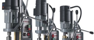
Machine bed for metal and wood processing
The smallest table saw and the largest rolling mill have one thing in common: the bed. All its moving and fixed components and parts are attached to it. The frames are made of durable alloys, because they can withstand not only the weight of the tank, but also the forces generated during its operation. Over time, the beds wear out; to extend the life of the machine, they are subject to renewed repairs.
What is a bed
The bed is the basis of the machine design. All other moving and fixed parts and assemblies are attached to it. Through it, the mechanism rests on the foundation. The bed absorbs all the forces that arise when the tool acts on the workpiece. From certain points on the frame, selected by the origin of coordinates, the movements of the moving parts of the machine are measured. It includes components such as:
- body elements;
- transverse, longitudinal and vertical fastenings and stiffeners;
- guides.
The bed is the longest-lived part of the machine, designed for the entire period of its operation. Engines, drives and working parts can be replaced many times as they wear out; guides only undergo periodic repairs. Guides are used for longitudinal, transverse or vertical movement of the moving parts of the mechanism.
There are two types of guides:
- open, used when processing parts of large and medium weight and small overturning moments;
- closed, used for medium masses of parts and significant overturning moments.
Movable units can move by sliding along guides, or use roller or ball bearings.
In addition to transmitting, distributing and compensating forces, the frame must also be able to dampen vibrations of various frequencies that are excited in the mechanism during its operation.
Types of beds
The bed is a different design in cross-sectional shape with:
- ring type profile;
- box profile;
- box profile and longitudinal stiffeners;
- box-type profile and stiffener located diagonally;
- open profile type;
- open profile and double walls.
In the longitudinal direction, the bed is a base with:
- square windows;
- windows and stiffener diagonally in one direction;
- stiffening ribs in both directions (like the letter X);
- one-piece body design.
Types of machine beds
There are two main types of products:
- horizontal supports;
- vertical racks.
For horizontal ones, their shape and cross-section are selected based on the following factors:
- optimal placement of components and parts;
- automated or manual removal of chips and other production waste;
- minimal interference for supplying transmissions and communications to engines, drives, and working parts;
- removal of coolant and chips;
- providing calculated indicators of strength, rigidity, vibration absorption and noise reduction;
When designing vertical posts, maximum attention is paid to their rigidity. To do this, choose the best cross-sectional shape, combining hollow volumes with solid casting, introducing additional walls, partitions and stiffeners.
When designing hatches and revisions through which diagnostics and maintenance of mechanisms are carried out, a compromise has to be reached between the convenience of service work and the requirements for maintaining rigidity.
When choosing the cross-section of frames for a milling machine, preference is given to trapezoidal shapes, which best transmit and distribute both weight and work loads from parts and assemblies of large and heavy mechanisms.
For the beds of lighter machines, rectangular and even triangular sections are becoming available.
Beds are also divided into monolithic and prefabricated, consisting of several separately cast and machined parts, which are connected into a single whole with detachable or permanent connections.
Technical requirements for beds
Technical requirements are formed in order to achieve compliance between the actual performance of the machine and the design requirements. It is also necessary to ensure a balance between productivity indicators and the cost of manufacturing the product.
A separate important section of technical requirements is the requirements for the materials from which one of the most important parts of the machine should be made. Regulated:
- alloy grade;
- physical, mechanical and chemical properties;
- homogeneity of structure, strength and elasticity both in general and separately in the most important and loaded areas;
- hardness of the guide material.
Another section of the requirements is the geometry of the structure. The accuracy of the entire machine depends on the accuracy of the dimensions, especially the guides. They serve to move the working bodies that directly process the product being manufactured. It is equally important to maintain the accuracy of manufacturing work tables, marking plates and other types of equipment for placing, securing and moving workpieces.
The machine bed is the coordinate reference point (or points) for marking and processing the product.
Geometric requirements regulate both the dimensions themselves and their maximum deviations, parallelism of surfaces, maximum permissible curvature of guides, slope angles and mating radii.
An important section of the requirements relates to vibration absorption and noise insulation. It describes the maximum permissible indicators for mechanical vibrations of machine structures at various frequencies, and the levels of vibrations transmitted to the foundation. For noise absorption, special coatings are used, applied to both the external and internal surfaces of the body and ribs.
Beds and guides
The bed is the base of the machine, the strength, rigidity and wear resistance of which determine the quality of its work. The bed must ensure the correct relative position of the components and parts of the machine on its base surfaces. The latter carry fixed and movable units. The surfaces that support the moving parts of the machine are called guides.
Depending on the position of the machine spindle axis and the direction of movement of the moving parts of the bed, they are divided into horizontal (bed) and vertical (rack).
Figure 1 – Section of horizontal (a) and vertical (b) frames
The beds of most machines are made by casting from gray cast iron of various grades (SCh-32; SCh-21; SCh-15). Modified cast iron MSCh-36 and MSCh-26 is also becoming widespread, it is more wear-resistant, allowing less chill, which makes it possible to cast parts with a maximum wall thickness of 5-7 mm. Welded steel frame structures are also used (in single production). With equal rigidity to cast iron frames, they have less weight (up to 2 times) and greater wear resistance. Welded frames are cheaper than cast ones. For welded frames, steel grades St 3 and St 4 are used. To relieve internal stresses, the frames are subjected to natural or artificial aging before machining.
Guides are the most important part of the frame and serve to ensure linear or circular movement of the moving elements of the machine. There are sliding and rolling guides.
Figure 2 – Roller guides
They are divided into covered and encompassing.
Figure 3 – Basic cross-sectional shapes of sliding guides:
a- rectangular; b – prismatic; c- dovetail shaped; g – round
Male guides have a convex profile that does not hold grease well, but they are easy to manufacture and do not trap chips. Therefore, they are used to move supports, tables, and headstocks at a feed speed in lathes, milling, drilling and other machines. Female guides have a concave profile that holds grease well, but requires good and reliable protection from chips and contaminants. They are used at high sliding speeds in grinding, rotary, longitudinal planing and other machines.
According to their profile, guides are divided into rectangular, prismatic, dovetail and round. Combined guides are often used in machine tools.
Rolling guides are becoming increasingly widespread in medium and light CNC machines, in jig boring machines, in grinding, copying machines, etc. The main advantage of guides is the low resistance to movement, 15-20 times less than in sliding guides, the absence of jumps at movement speeds less than 12 mm/min, high accuracy of installation movements, backlash-free and durable. However, during production they require significant costs, high-quality and precise processing of working surfaces and their reliable protection.
The most widely used are hardened guides made of case-hardened steel 20X and chromium ball-bearing steels ШХ9, ШХ15, ШХ15СГ, with a hardness of 60-62 HRC and from cast iron SCh21 with a hardness of 200-250 HB.
Guides in which oil or air under pressure is supplied to the mating surfaces in a special groove in order to create a constant oil or air layer over the contact area are called hydro- or aerostatic guides.
Hydrostatic guides are mainly used in heavy machine tools. To improve the quality of metal-cutting machines, elements are required that have high rigidity and load capacity, high efficiency, minimal wear with no gaps, high smoothness of movement and positioning accuracy, as well as the ability to maintain initial accuracy for a long time. The listed requirements are best met by guide gears with hydrostatic lubrication, i.e. hydrostatic guides. Hydrostatic guides create an oil cushion over the entire contact area of the guides.
The separation of working surfaces in aerostatic guides is achieved by supplying air under pressure into the pockets. As a result, an air cushion is formed between the mating surfaces of the guides. In design, aerostatic guides resemble hydrostatic ones.
The disadvantages of aerostatic supports and guides compared to hydrostatic ones are low load capacity, low vibration damping, since the viscosity of air is four orders of magnitude lower than the viscosity of oil, as well as low dynamic characteristics, a tendency to failure due to clogging of the line and working clearance.
The advantages of aerostatic guides are that they provide a low coefficient of friction when moving, and when the air supply is turned off, surface contact with high friction is created very quickly, providing sufficient rigidity for fixing the machine unit in a given position. There is no need for the locking devices that hydrostatic guides require.
In aerostatic guides, air is supplied under an excess pressure of 0.2 - 0.4 MPa. Aerostatic guides are used in precision machines where cutting forces are low and precise positioning is required.
Spindle units
Spindle is the shaft of a metal-cutting machine that transmits rotation to the cutting tool fixed in it or to the workpiece being processed. Medium-load spindles are usually made of steel 45 with improvement (hardening and high tempering); at increased power loads, steel 45 with low tempering is used. For spindles requiring high surface hardness and a tough core, steel 45 with high-frequency hardening and low tempering is used.
The structural shape of the spindles depends on the method of installing clamping devices on it, for fastening the cutting tool or workpiece, the fit of the drive elements and the through hole for the passage of the rod. The front ends of the spindles of general purpose machine tools are standardized.
Figure 4 — The design of the front spindle support of a lathe.
1,2 – nut; 3 – device for preloading thrust bearings; 4-thrust bearing; 4 – thrust bearing; 5 – bushing; 6 – inner ring of the bearing; 7 – labyrinth seals; 8 – spindle.
Rolling and sliding bearings are used as supports for machine tool spindles. Spindle units must be of high quality. Therefore, rolling bearings used in spindle supports must be of high accuracy classes. The choice of bearing accuracy class is determined by the runout tolerance of the spindle actuating surfaces (tapered hole and mounting surfaces for installing chucks, for fastening tools and workpieces), which depends on the required processing accuracy. Typically, the front support uses more precise bearings than the rear support.
Sliding bearings used as spindle supports can be unregulated (they are rarely used), with radial, axial clearance adjustment, hydrostatic (they provide for the supply of oil under pressure into several pockets, from which it is forced out through the gap between the spindle journal and the bearing), hydrodynamic and with gas lubrication.
Precision machines use hydrostatic bearings, which create high precision spindle rotation. Their load-bearing capacity, rigidity and accuracy depend on the size of the gaps, pressure, and support pattern.
Hydrostatic bearings stabilize the friction mode with the lubricant at the lowest rotation speeds.
4 Typical machine mechanisms (advanced task)
Mechanisms of rectilinear motion
The mechanisms used to convert rotational motion into translational motion can be divided into two groups.
The mechanisms of the first group provide forward and reverse motion per revolution of the driving link. These include crank - connecting rod, rocker, cam
etc. In the mechanisms of the second group, which include rack
a change in the direction of movement is achieved by changing the direction of rotation of the drive link.
Crank and rocker mechanisms
used in the main movement chains of high-speed machines with a small tool stroke. The tool stroke in these mechanisms is adjusted by changing the crank radius R, and the work zone by changing the length l of the connecting rod or the position of the tool relative to the slide.
Figure 5 - Crank-rod (a) and crank-link (b) mechanism
Cam mechanisms
, converting rotational motion into rectilinear translational (continuous and intermittent) are used mainly in the feed mechanisms of automatic and semi-automatic machines.
Figure 6 – Cam mechanisms
Intermittent movements can be performed with various periods of stopping, single or multiple actions in one cycle. The driving element of the cam mechanism is usually a deck or cylindrical cam, which in most cases rotates continuously. The driven link, called the pusher, performs a reciprocating or rocking motion and has a force or geometric closure with the cam. Power closure is carried out by the own weight of the mechanism links, load or spring force, geometric closure - by two cam surfaces covering the pusher roller or two rollers covering the cam.
Rack and pinion gears
provide significant movements of the driven link per one revolution of the driving link and a high coefficient of efficiency (efficiency). According to their design, they can be gear-rack and worm-rack (worm and worm rack, worm and gear rack).
Rack and pinion transmission
widely used in feed drives for turning, drilling, boring, longitudinal planing, broaching and other machines.
Worm and rack
gears are self-braking gears that transmit movement only from the worm to the rack and have greater rigidity and smoothness in operation than a gear and rack, due to the fact that several rack teeth are simultaneously engaged with the worm. The location of the worm at an angle to the rack allows you to have a drive located beyond the dimensions of the table, which simplifies the layout of the machine.
Screw-nut transmission
has self-braking, high accuracy and smooth movement of the driven link during large and small movements. In machines they are used in three types: sliding, rolling and hydrostatic. Sliding screw-nut transmissions are simple in design and easy to manufacture, have low friction losses and high efficiency. They usually have a trapezoidal thread with an angle of 300, which allows the use of split nuts. In high-precision thread-cutting machines, gears with a rectangular thread profile or trapezoidal with a reduced profile angle (10 - 150) are used. Sliding bearings in the form of bushings made of bronze or anti-friction cast iron are more often used as supports for lead screws, because They are small in size, simple in design and provide the necessary accuracy of screw position. To absorb axial loads, high-precision thrust bearings or sliding bearings are used.
Figure 7 – Mechanisms for converting rotational motion into translational motion.
a – rack and pinion transmission; b- worm and rack gear; c – hydrostatic worm-rack transmission; d,e – sliding screw pair; e – ball screw drive;
1 – worm; 2 – hydraulic distributor; 3- rack; 4.5 – pumps; 6 – caliper; 7 – locknuts; 8,10 – nuts; 9 – body; 11 – lead screw; 12 – rolling bodies; 13 – return channel; M – electric motor
To move the components of heavy machine tools, hydrostatic screw-nut transmissions are used. An oil layer is created between the turns. This reduces the wear of the pair and increases the transmission efficiency to 0.98 -0.99. The rigidity of the oil layer under certain conditions can exceed the contact rigidity of a conventional transmission by more than 5 times. The hydrostatic screw-nut transmission is backlash-free, because pressure is applied on both sides of the coils, which ensures high uniformity and smoothness of movement.
Intermittent Motion Mechanisms
To convert rotational and rocking motion into intermittent (periodic) ratchet, Maltese, cam and other mechanisms are used.
Ratchets
can be with external and internal gearing. In an external gear mechanism, the pawl receives a rocking motion. When moving forward, the pawl through the teeth of the ratchet wheel turns it through a certain angle. During the reverse stroke, the pawl slides along the teeth of the ratchet wheel without rotating it. The rocking movement of the pawl of the ratchet mechanism is often carried out using a crank mechanism.
Maltese
mechanisms are most often used for periodically turning turret heads, spindle blocks, tables of multi-spindle automatic machines, etc. at a constant angle.
Maltese mechanisms can be correct or incorrect. For correct mechanisms, the cross has grooves with a uniform pitch; Irregular ones have different angles between adjacent grooves of the cross. As a rule, the machines use correct Maltese mechanisms with external gearing and radial grooves.
In the Maltese mechanism, when the crank rotates, its lantern or roller enters the groove of the cross and for each revolution turns it by 1/z part (z is the number of grooves), i.e. gear ratio of the Maltese mechanism i = 1/z.
In order for there to be no hard impact at the beginning of the rotation of the cross, when the shank engages, the initial angular velocity of the cross must be equal to zero. Otherwise, it is necessary that the shank fits into the groove of the cross in the radial direction.
Figure 8 – Ratchet mechanisms with an asymmetrical (a), symmetrical (b) tooth profile and a flat Maltese mechanism.
1- ratchet wheel; 2 – dog; 3 – lever; 4 – crank mechanism; 5 – crank disk; 6 – finger; 7 – screw; 8 – pin; 9 – shield; 10 - Maltese cross; 11 – roller; 12 – crank; α is the angle that determines the position of the grooves of the Maltese cross; β – angle between the axes of the crank and the Maltese cross
Metals for the production of frames and their main properties
What material are machine beds made of? Traditionally, the main materials for the manufacture of frames for various equipment were metals and their alloys.
In the 17th-20th centuries, cast iron was most popular. It still retains its leading position today, but is gradually retreating under the onslaught of various types of steel, light metal alloys, plastics and composite materials.
Considering the general trend towards reducing the weight and dimensions of equipment and increasing their efficiency, broad prospects are opening up for advanced materials.
For the beds of light and medium-sized machines, such replacement is taking place at an accelerated pace. For heavy equipment, a significant part of the functions of the frames is transferred to the reinforced concrete foundation reinforced with modern materials.
However, for highly loaded machines and production complexes, such as rolling mills, heavy presses, forging machines and steel foundry equipment, special grades of cast iron are still unrivaled.
Its unique ability to withstand large static loads, high guide strength and corrosion resistance distinguish cast iron from competing materials. Cast iron alloys with nodular graphite, modified with cerium additives, have the same performance characteristics as steel and are significantly cheaper to produce.
Beds
The main requirement for the machine bed is the long-term provision of the correct relative position of the components and parts mounted on the frame, under all intended operating modes of the machine, which is achieved by the invariance of the correspondingly located base surfaces for the main components of the machine on the frame. The reference surfaces for moving parts are called motion guides and translation guides.
From this follows the requirements for frames, along with the requirements for strength, ease of manufacture, low “metal consumption” and fairly low cost, the main requirement for the invariability of the shape of the frame, which is achieved: by the choice of material of the frame and the technology of its manufacture, such rigidity of the frame that its deformation under the influence of the greatest efforts during operation of the machine do not go beyond the limits consistent with the tolerances for inaccuracy of processing, the vibration resistance of the bed (as well as other parts of the machine), and the sufficiently high wear resistance of the guides. The shape of the bed is determined primarily by: the location on it of guides for various machine components; weight, dimensions and stroke lengths of the main parts and components of the machine; the need to place various mechanisms inside the frame; the need to install openings, windows and holes in the walls of the frame for installation and dismantling, for inspection, adjustment and lubrication of machine mechanisms, and on the walls of the frame - brackets for mounting various types of devices.
The operation of high-performance machines is often accompanied by the separation of large quantities of chips - sometimes hundreds of kilograms per hour. The requirement for rapid removal of chips - one of the most serious when designing modern high-speed machines - greatly influences the shape of the bed: windows and openings must be made in it for the free fall of chips, slopes inclined towards the rear wall of the bed, etc. In the beds of modern high-performance machines, it is often space is provided for a built-in conveyor that continuously removes chips.
When designing a cast frame, general foundry technical requirements must be observed, with the goal of facilitating molding and reducing shrinkage stresses. The bed must be sufficiently rigid. However, to ensure the rigidity of the elastic system machine - workpiece - tool, this is still not enough, since the choice of feed and depth of cut, permissible with the required accuracy and cleanliness of the machined surface and durability of the tools, depends on the rigidity of the entire specified system. Hence the desire to connect the main parts of the machine so that they form a closed frame, to cast the bed integrally with the headstock body and to use “monolithic” (“monoblock”) structures.
The rigidity of the bed is greatly influenced by the ribs connecting it to the machines or molded to them. Their effectiveness in increasing the rigidity of the structure depends on the location of the ribs, their number, shape and cross-sectional dimensions. Studies carried out on models of frames of various shapes have shown, for example, that the location of the ribs connecting the walls of the frame (partitions) is practically indifferent with regard to the vertical rigidity of the latter. To increase vertical rigidity, it is advisable to mold ribs to the walls in the form of longitudinal horizontal shelves or a diagonal mesh.
The location of the ribs and their shape have a great influence on the horizontal rigidity of the frame. The most effective in this regard are diagonal ribs (partitions). Ribs in the form of shelves or a diagonal mesh also have a beneficial effect on horizontal rigidity, especially when combined with partitions. Diagonal ribs also increase the torsional rigidity of the frame.
The following materials are used to make the frames.
Gray cast iron. Machine beds are mostly cast from ordinary gray cast iron, although other types of cast iron are also becoming increasingly used. The decisive influence on the choice of grade of gray cast iron is exerted by the guiding movements, which must have high abrasion resistance. When designing frames (as well as other castings), it is necessary to avoid sudden changes in thickness, since otherwise the cooling rates at different points of the cross-section of the casting will be different, which can lead to the appearance of cracks in places where the section thickness changes.
Modified cast iron. Modified sorbitol-perlite cast iron is increasingly used for the manufacture of beds and other critical parts of machine tools. Its wear resistance is 2-3 times higher than that of unmodified perlite cast iron, especially at specific pressures above 15-20 kg/cm2 and friction with a lubricant clogged with abrasive. Also, in terms of mechanical properties (strength limits, endurance limits, elasticity modulus, etc.), modified cast iron is better than ordinary perlite, approaching steel. The hardness of modified cast iron in its unheated state, and its machinability is the same as that of ordinary gray cast iron of the same hardness. Modified cast iron can be hardened by heating. h. or flame to high hardness, which is used to increase the wear resistance of the guides.
It should be noted that currently castings made of gray unmodified cast iron are also heat treated. Experience shows that during the heat treatment of such cast iron, cracks occur less frequently than during the heat treatment of modified cast iron.
Steel. In modern machine tool building there is a tendency to replace cast frames with welded ones made of rolled steel. This trend is due to a number of technical and economic reasons.
As a material for making frames, cast iron has many advantages (the ability to produce castings of almost any shape, good machinability - better than steel, the ability to dampen vibrations, etc.). However, one should take into account a number of inconveniences associated with the manufacture of beds by casting: a) lengthening the production time of the machine due to the need to pre-make the model and core boxes, as well as to withstand the casting before processing and after grinding for quite a long time; b) possible casting defects, and some defects are discovered only during the machining process; c) the need to leave fairly large allowances on the casting surfaces; d) with guides that are integral with the frame, cast iron must be selected according to the requirements for the guides; e) with long-term aging of castings, the turnover of the enterprise's working capital slows down and the cost of unfinished products increases; f) in small series, the cost of the machine is adversely affected by the cost of manufacturing the model and core boxes, and in large-scale production, the influence of this factor can be so insignificant that it can be neglected.
Frames made by welding from pre-cut pieces of rolled steel are free from all these shortcomings.
The guides are welded or bolted to the bed, so the bed can be made from cheap, fabricated carbon steel.
The elastic limit and mechanical properties of steel are significantly higher than those of conventional cast iron; therefore, the material consumption for a steel welded frame is much less than for a cast iron one, with the same forces and moments in both cases, if the safety margin and rigidity of both frames are assumed to be the same. With equal rigidity, the weight of a steel element is 0.5-0.75 of the weight of a cast iron element, i.e., the metal savings is 50-25%. In practice, metal savings when replacing a cast iron frame with a steel one greatly depend on the design of both options.
When deciding whether a cast iron or steel frame is preferable for the machine being designed, it is necessary to take into account the entire set of technical and economic indicators of both options. For large-scale production, a cast frame is often more appropriate, and if it is necessary to quickly manufacture one or more machines, a steel frame is more appropriate.
For the manufacture of welded machine beds, you can use sheet steel with a thickness of S > 3 mm. With small wall thicknesses, the necessary rigidity of the frame must be ensured by a sufficiently large number of ribs. As a result of this, as well as the large number and length of welds, it may turn out that the same frame, made of steel with a thickness of 10-12 or even 15 mm, turns out to be no heavier and at the same time less labor-intensive.
In addition to the listed materials, steel cast iron, alloy cast iron, nitrided cast iron, and concrete in heavy machine tools have also received some use for the manufacture of beds.
Bed structure
The main components of a lathe bed design can be seen from the sectional drawing of the lathe bed:
- supporting surface;
- longitudinal ribs;
- transverse ribs connecting longitudinal ones;
- prism-shaped guides;
- flat guides designed for attaching headstocks and moving calipers.
The ribs are formed during the casting of the workpiece for the machine bed
The cross-section of prismatic guides can take various shapes, based on the directions of the forces arising during operation and their magnitude. Both guides must be strictly parallel in space and have a perfectly smooth and even supporting surface. Otherwise, there can be no question of the accuracy of processing parts on the machine.
To achieve this result, they are subjected to high-precision milling or processed on a planing machine. Next comes grinding and scraping. During this processing, geometric parameters are repeatedly monitored for compliance with technical specifications. The final check is carried out after assembling the machine and installing moving parts and components on it.
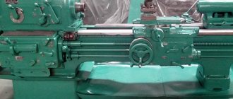
Machine bed
The lathe bed serves as the base. It has two longitudinal walls in its design. These walls connect the ribs to each other in the transverse direction. On top of the frame there are four guides. Of these four, three are prismatic in shape and one is flat. At the left edge of the frame at its end there is a place where the headstock is secured. In the opposite part, on the edge on the inside of the guides, the tailstock is installed. This headstock can be moved freely along the frame along the guides and fixed at any point. The plate carriage also moves along the frame guides, which are prismatic. In order to process parts with high precision, all bed guides must be carefully machined along all planes. The strictest straightness and parallelism must also be observed.
Main purpose
The purpose of the bed is determined by its role among the components of the machine.
It is one of the main parts and is designed to perform the following functions:
- fastening and placement in a certain spatial order of all other parts and assemblies of the product;
- perception, distribution and transfer to the foundation of static and dynamic loads caused by the weight of parts and arising during the operation of the machine;
- creating conditions for moving the working parts of the machine and workpieces with the required accuracy along guides and work tables.
Bed repair
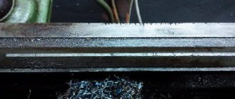
Despite the high quality of materials and precision manufacturing, during operation the frame experiences significant loads and inevitably wears out. These processes are most noticeable on the surface of the guides, which loses its geometric and strength properties.
To restore working properties, periodic or unscheduled repairs of guides are carried out. To perform the scraping operation, moving parts are removed from the machine, and the bed itself is fixed on a rigid, massive foundation. The operation is then carried out in the following sequence:
- the linearity of the longitudinal and transverse profile is checked using a frame level;
- if the deviation exceeds 0.02 mm per linear meter, scrape one of the guides using a ruler and paint for verification;
- in parallel, the degree of inversion is controlled;
- after bringing the deviation to the specified values, they move to the second guide.
After scraping, the surface is polished.
Machine bed - purpose, repair and more.
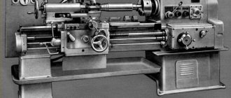
The bed of a machine, lathe or other, is the main basic part on which almost all components and parts are located and secured, and all moving mechanisms and parts move relative to the bed. This article will describe in detail all the important points related to the accuracy, checking and restoration of the lathe bed using scraping, and will also consider devices for this and other nuances.
The bed of any machine must have a sufficiently high rigidity, ensure that the machine maintains the required accuracy for a long time, and at the same time allow the chips to be freely removed from the cutting zone. Moreover, with sufficient rigidity and accuracy, the dimensions and weight of the frame should be minimal. Of course, the designs and shapes of the beds are different and they are determined by the purpose and dimensions of the machine.
The bed of a medium-sized lathe is cast in the form of a hollow body part (see Figure 1), and to give the machine bed greater rigidity, with low weight (and with the ability to remove chips), the longitudinal ribs of the bed are connected diagonally (Fig. 1b) or parallel ( Fig. 1 a) partitions that are cast as one piece with the frame.
Well, on the longitudinal edges of the frame there are guides that are designed for longitudinal movement of the machine support and tailstock. The size and shape of the bed guides vary, for example, on most medium-sized machines, as a rule, they make a combination of flat and triangular shaped guides, with the outer guides used to install and move the support, and the inner guides used to install, move and secure the tailstock.
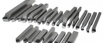
As I already said, the beds of metal-cutting machines (as well as the beds of hammers and steam engines) usually have flat, triangular (V-shaped) guides, as well as prismatic ones. And dovetail-shaped guides are made on supports and tables of metal-cutting machines, various slides, etc.
The accuracy of any machine, of course, depends on the manufacturing accuracy and condition of the bed guides and other mating parts, so the machine guides are carefully processed (or restored if the machine is worn out, and how and with what help this is done, I will write in detail below).
As a rule, machine beds are cast from gray cast iron (its number according to GOST 1412-70). Most often, the beds of small and medium-sized Soviet machine tools were cast from gray cast iron, grade SCh21-41, while the beds of heavier machines were cast from gray cast iron, grade SCH32-52.
It should be mentioned that beds cast from cast iron have a low machine cost, have greater vibration resistance, and are also easier to process and restore). But the main disadvantage of cast iron beds is that their guides are short-lived, as they wear out quickly, and the weight of a cast iron bed is quite large (although for many machines, high weight is more of a plus than a minus).
And therefore, in order to avoid the disadvantages described above, they are increasingly beginning to produce welded frames from steel, which is naturally more wear-resistant than cast iron. And for some rare heavy and large machines, frames are made of reinforced concrete.
But still, cast iron frames are the most common and have their advantages. In addition, with careful care (timely lubrication and removal of chips), cast iron beds are quite durable, and it is almost always possible to restore a worn bed, and with your own hands, without having expensive planing or grinding machines, and how to do this with the help which I will describe in detail below.
Assembling the frame (and other components) with parts moving progressively along it comes down to finishing the guides and adjusting the mating of these parts. In mechanical engineering, surfaces of progressively moving mating parts are finished using scraping, finishing planing with wide cutters, as well as grinding and lapping.
But despite the fact that scraping is a rather labor-intensive operation (and where possible it is replaced by grinding), it is used to restore the guides of the frame (and not only). After all, not everyone has a grinding machine. And to restore the machine bed using scraping, you just need to buy a scraper and some other tools and devices (which, by the way, you can make yourself, but this will be written below), and be patient.
I have already written in detail about scrapers (what they are) and scraping here, and the basics of the scraping process itself, quality control and other important nuances are also described there. Therefore, if you decide to competently restore the frame of your machine with your own efforts, it is advisable to first read the first article about the scraping process by clicking on the link above, and then read what I will describe below.
Scraping the bed of a lathe, as well as the progressively moving parts mating to it.
Below I will describe the scraping of the bed and progressively moving parts of a lathe, which has a bed guide length of more than 3 m. If the machine has smaller parts, the work will become even easier.
And so, before starting work, first you should remember that the planes shown in Figure 2 must meet certain requirements, which I will list below:
- the frame guides must be straight in the longitudinal direction within 0.02 mm over a length of 1 meter (1000 mm);
- and the non-parallelism of the guides along their entire length should not exceed the same 0.02 mm;
- in addition, the machine bed should not be spirally curved along its entire length; only a deviation of 0.03 mm is allowed (the smaller the better) over a length of 1 meter (1000 mm);
- the (lower) parts of the caliper mating to the frame must fit snugly against the frame guides, or it is permissible to insert a probe with a thickness of no more than 0.04 mm end-to-end between it and the guide, at a length of no more than 25 mm;
- the transverse guides of the lower part of the support must be parallel to each other and exactly perpendicular to the guides of the frame, while the tolerance for deviations from parallelism and perpendicularity is no more than 0.02 mm, again over a length of 1000 mm;
- and the accuracy of scraping the guides should be such that when checking for paint, you get 12-15 spots in a square from a frame measuring 25x25 mm (I already wrote in detail about quality control in the article about scrapers and scraping - link to the article above);
The process of scraping the machine bed.
Before scraping, the frame must be installed on a massive base and then, using a block (or frame) level, the frame must be aligned in the longitudinal and transverse directions. We start scraping from the base surfaces.
Machine bed with support: 1 - plane for the tool holder, 2 - transverse slide, 3 - guides for the transverse slide, 4 and 13 - surfaces of the support mating with the frame, 7,8,9 - guides for the sole of the tailstock, 5,10 and 12 - upper guides for the caliper, 6 and 11 - lower guides for the caliper clamping bars, 14 - wedge of the transverse slide, 15 - 18 - transverse guides for the caliper.
And the base surfaces on the bed are chosen so that all other guides can be scraped relative to them, and the machine support, planes 6, 8, 12 can be installed and adjusted - see Figure 2.
The planes intended for scraping (that is, the guides of the machine bed) are checked for paint with a special ruler (for example, ШД-630 - GOST 8026) or a special plate 3 (see Figure 3 below), in which the profile of the working surface applied to the guides corresponds to the profile of the bed guides that need to be restored by scraping (those who don’t have a plate can also use a machine support, but of course it can be worn out and therefore it is preferable to use a plate).
On top of the slab 3 there is a special flat control platform, which is parallel to the lower surfaces and on which a block or frame level is installed.
Punching beacons on the guides of the machine bed: 1 and 2 - carriage guides, 3 - scraping plate, 4 - level.
Triangular (prismatic) and flat guides are first roughly scraped along a ruler, and then so-called beacons are applied to the roughly scraped surfaces.
The essence of applying beacons is that on the surface of the guide, only a small area is scraped along the slab, which is slightly larger than the length of the slab itself. And you should scrape until the planes of the guides begin to be evenly painted over when checking with a slab for paint (I wrote in detail about checking for paint in the article about scrapers and scraping - link above).
Well, the level installed on the upper platform of the slab should not indicate deviations from the horizontal plane, neither in the transverse nor in the longitudinal directions. Beacons are applied at both ends of the guides, but if scraping is done using a ruler and level, then on the rest of the machine bed you need to apply beacons at such a distance from each other that the length of the control ruler overlaps them. And the closer the beacons are placed to each other, the more accurate the scraping of the guides will be.
The middle beacons are applied in the same way as the extreme ones, but as they deepen, the scraping of the beacons themselves is constantly controlled with a ruler, a plate or an “airplane” (a bridge - more about it below) with a level set on them.
By performing each of the beacons (with control over its neighbor), we gradually bring all the beacons to the same level and ultimately they will all be located on the same straight line. It should be taken into account that all beacons should be placed and executed very carefully, because later they will serve as the basis for scraping the areas between them (the beacons).
We scrape the areas between the beacons using a ruler in the usual way, but do not scrape the painted areas (spots) on the beacons themselves. Well, we scrape the areas between the beacons until the surface between the beacons and on the beacons is covered with evenly spaced spots, but in fewer quantities than is necessary for the finally scraped surface of the guides.
After finishing scraping the areas between the beacons, you should check the entire surface of the guide for straightness; if necessary, we correct inaccuracies and then you can begin finishing the final scraping. The final scraping is carried out by the shine of the slab (I wrote about checking the shine in the first article about scraping - link above) or by the shine of the caliper, and we check the entire surface of the guides using a ruler and level.
After scraping the main base (guides under the caliper), scrape further the planes of the tailstock guides - these planes 5,7 and 10 are shown in Figure 2.
The guide planes of the machine bed, shown in the figure as numbers 5 and 10, are scraped along the beacons and checked using a plate, as described above. Well, we check the parallelism of plane 10 and the prismatic guide 7 of the tailstock using an indicator that is installed on the plate (I will talk about the special device bridge, or as it is also called “airplane”, in more detail a little later).
Scraping the caliper.
In general, this article is about the machine bed and its restoration, but other parts of the machine are also associated with the bed, which also wear out and should be restored, and of course there is no point in restoring only the bed. Therefore, scraping the caliper will be described below.
Scraping the lower part of the lathe support should begin with adjusting the lower guide sliding surfaces that mate (rub) with the bed guides. These planes are shown in Figure 2 under numbers 4 and 13. And since the length of these planes is very small, they are scraped and checked against a ruler and the machine bed (or against a special plate that has a profile of the working surface of the bed guides - that is, a model of the bed ). The lower sliding surfaces of the lower part of the caliper are finally scraped along the bed guides.
And when scraping of the lower guides and the lower part of the caliper is completed, you can begin scraping the transverse guides of the caliper, the profile of which is made in the shape of a dovetail - these are the surfaces numbered 16,17,18 shown in Figure 2. These surfaces (planes) are used for movement cross slide of the caliper.
Scraping the caliper and checking the straightness of the lower caliper guides: A - scraping using a scraping plate, B - checking the caliper guides with a slider with an indicator, C - checking the caliper guides using rollers, D - checking the guides with a slider with an indicator and a control square, D - scraping the inclined surfaces of the guides with a scraping plate.
To begin with, we roughly scrape all mating surfaces along an angular ruler, and then place the lower part 1 of the support on the bed (see Figure 4a) and using a special scraping plate 2 we scrape the transverse guides that mate with the cross-feed slide of the machine support (if there is no special plate , then we scrape it manually with a scraper, constantly checking the paint with an angled ruler).
When we achieve a uniform distribution of the spots, we can scrape the second corner (inclined) plane of the dovetail. During operation, it is necessary to periodically check the planes using a special device (slider), shown in Figure 4b, on which a 3-dial indicator is attached. In this device, cylinders 6 are installed, which are pressed with screws 7 and pin 8. The cylinders 6 of the device have an accurate profile of the dovetail dihedral angle, should be pressed tightly to the planes being checked, then the nose of the indicator fixed on top is rested against the shelf of the control square 13 (see Figure 4d).
Square 13 should be installed on a special stand (possibly on the bottom plate of the tailstock) and then one of the sides of the square should be placed exactly parallel to the guides of the machine bed. And now, when moving the device (slider 11) along the entire length of the inclined dovetail guide, the nose of the indicator 12 will slide along the side of the triangle and show the deviation of this surface from perpendicularity. If the inspection shows satisfactory results within the tolerances (I wrote the tolerances above), then final (finish) scraping can be performed.
For those who do not have such a device, to check the parallelism of the planes, you can use two identical rollers shown in Figure 4c (for example, rollers from a bearing of a suitable diameter) and a 9 caliper (preferably a micrometer).
Final scraping.
We do the final scraping along the guide planes of the transverse caliper. And when the adjustment of the three planes of the transverse guides of the caliper (one inclined and two flat) is completed, then wedge 14 should be scraped down (Fig. 2).
At the same time, we apply paint (for example, Prussian blue) to those surfaces of the slide that mate (contact) with the wedge, then we put the transverse slide on the guides and, using a small hammer, we apply gentle blows to the wedge and insert it between the planes of the caliper guides and the slide.
Now you need to move the cross slide (together with the wedge) back and forth several times and then carefully remove the wedge. All that remains is to follow the traces of paint (meaning bulges) and remove them using a scraper from the surface of the wedge, that is, scrape it.
If a new wedge is being made, then after final scraping we cut off the excess (lengthwise) from the wedge and mill a cutout for the wedge adjusting screw.
Checking the parallelism, straightness and spiral curvature of the machine bed.
Various devices are used for testing. The most common device, called a bridge (popularly “airplane”) is shown in Figure 5. It has a base 1, made of sheet metal, at least 10 mm thick, which has a T-shape (sometimes H-shape) and four supports 5, and an additional support 3.
The supports numbered 5 in the figure have the ability to move in a vertical plane along pins 7 and clamp them with nuts 6. The other two supports can move in a horizontal plane (along longitudinal grooves), and they are fixed in the desired position using nuts 4. Well and the supports 5 can move apart and move, depending on the width of the frame guides and the difference in the distance between them. And support 3 is capable of moving in horizontal and vertical planes.
There is also a block 8, which is rigidly fixed to the base 1 using screws (they are not shown in the figure), and a frame level 9 is attached to the block 8 using screws 10. The fixed level must be with a division value of the main ampoule of 0.02 ( well, or 0.05) per 1000 mm. The device also has special clamping units 11 into which two dial indicators 2 are attached. The position of the indicators 2 can always be adjusted, and the clamping units securing them can be fixed in different places on the base (depending on the size of the machine bed).
Figure 6 shows examples of checking guides using a special device - a bridge (popularly called an airplane). Figure 6a shows the testing of guides with a triangular (trapezoidal, prismatic) profile. Guides with this profile are usually made on the beds of turret lathes.
As can be seen in Figure 6a, four supports 1 of the device (only 2 supports are visible in the figure) are placed on the left prismatic guide of the frame, and one support 3 rests on one of the sides of the right guide of the frame. The supports are made in the form of rollers - often in homemade devices of this type, bearings of suitable size are used, but it should still be taken into account that the bearings have gaps between the races. Therefore, it would be much more accurate to install rigid supports (sliders) instead of rollers (bearings).
When moving the bridge (airplane) along the guides of the frame, the parallelism of the left guide of the frame relative to the base surface is determined using the 4-dial indicator (the base surface in Figure 6a is where the nose of the indicator 4 rests).
And using level 2 (you can use a block level rather than a frame one) which is installed across the frame guides, the spiral curvature of the guides is determined (that is, the deviation of the guide surfaces in the horizontal plane). I published the tolerances for deviations above in the article, I hope this is clear, let’s move on.
Checking the second side of the right guide frame is done by level, you just need to move support 3 to this (second) side (the second support 3 is not visible in the figure), or simply by moving the indicator, resting its nose on the second plane of the right guide frame (for this check in Figure 6a, the indicator nose is shown with a dotted line).
Well, to check the straightness of the surfaces of the machine bed, the level must be placed on the bridge (plane) not across, but along the guides, and then the bridge should be moved along the guides, periodically stopping it at different parts of the bed and recording (taking) level readings.
Figure 6b shows a bridge installed on the bed of a lathe (popularly an airplane) for monitoring and checking the parallelism of the middle guides relative to the base surface. And the base surface is the plane for the rack (in Figure 6b this plane is shown as a thick short line and indicator 4 rests on it).
Also shown in Figure 6b is a method for checking the frame for spiral bending. Only the parallelism of the guides is checked using indicator 4, and the spiral curvature is controlled using a bar level 2.
Checking the outer guides is also carried out using a dial indicator and a block level, only after readjusting the bridge and installing it on these outer guides, or only using a dial indicator, and using the verified middle guides of the frame as a base.
Well, Figure 6c shows checking the guides of the grinding machine bed. For such machines (and some others), guides are usually made with planes of a different shape (a combination of a V-shaped and W-shaped profile) - they are visible in Figure 6c.
To check such beds for straightness and spiral curvature of the guides, four supports 1 are installed on them (between the V-shaped planes) and one support on the opposite plane of the other guide. Control (checking) is carried out using bar level 2.
Figure 6d shows a test option if the dimensions of the guides do not allow placing all the bridge (aircraft) supports between their forming planes. In this case, we install only two supports 1 and one support 3 on the second guide. We do not use other supports 1.
And Figure 6d shows such a bridge installation in which supports 1 are spaced at a decent distance between the prismatic surfaces of the guide frame.
Well, the last figure 6e shows how the flat guides of the frame are checked. During such a check, the main feature is that we rest two supports 1 against the side surface (only one support 1 is visible in the figure), and rest the remaining two supports and support 3 against the horizontal planes of the guides. This installation ensures accurate readings of the level 2 installed on the bridge.
As soon as the base surfaces have been prepared (checked), scraping of the bed guides can begin. Other methods of processing (restoring) machine beds.
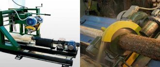
In well-equipped factories, scraping is replaced by grinding, since grinding is more productive and more accurate than scraping (of course, with high-quality equipment). In addition, grinding can also be used to process hardened parts that have high hardness.
To grind the guide frames of various machines, special grinding machines (universal or surface grinding machines) and special devices are used, which only large enterprises can afford. In the absence of grinding machines of suitable sizes, parts can be processed on milling, planing and rotary machines using special grinding heads.
Figure 7 A shows a diagram of grinding a lathe bed on a longitudinal planer using a universal grinding head. The use of such heads makes it possible to replace manual scraping in mechanical repair shops.
And Figure 7B shows the processing of the bed using a self-propelled grinding head. Its advantage is that it does not require large longitudinal planing machines. And thanks to a special device, such a head makes reciprocating working movements along the part being ground.
On the plate 5 there are replaceable guides 1 and 6 (see Figure 7B), and the grinding head 4 is an electric motor with an elongated shaft, at the end of which a cup abrasive wheel is attached. There are also two rotary supports 2 and 3, which allow you to install the head at the desired angle, and a worm gearbox with a separate motor moves such a grinding device.
Well, changing the rotation of the electric motor of the gearbox (to ensure reciprocating motion) is carried out automatically (using stops), or manually.
But still, for small garage workshops and simply amateur craftsmen who have a lathe or milling machine in their workshop that needs to be restored, scraping is the most accessible and inexpensive method of repair, and it will be used for a long time to restore machines.
And I hope that this article will be useful to many novice craftsmen who have decided to put the machine in order in their workshop, lathe or milling, it doesn’t matter, because the principle of repairing and checking the guides of the machine bed is almost the same, good luck to everyone.
If this article is useful to you, please share it on social media. networks by clicking the buttons below. Thank you.
RќСЂР°РІРёС‚СЃСЏ
Grinding the guides
During grinding, operations are performed in the following sequence:
- saw down and clean out surface nicks and burrs;
- the bed is fixed to the plate longitudinally - the planing installation;
- a level placed at the level of the tailstock is used to measure the degree of curvature of the guides;
- if necessary, correct the sagging of the structure using compensating spacers and wedges;
- the tortuosity is re-measured, the measurement results must coincide with the original ones;
- The surface of the guides is ground with a fine abrasive grinding bowl.
After restoring the surface of the guides, the machine is mounted on its own foundation and the previously removed moving parts are attached to it.
Over the life of the machine, this operation is performed several times, returning it to active production use.
Source of the article: https://stankiexpert.ru/tehnologicheskaya-osnastka/zapchasti/stanina.html