Screw-cutting lathes are used in various industries, most often they can be found in machine-building industries. Any work must be done with high quality, but details on which human life and health may depend must be done with special filigree, which can only be done on a perfectly adjusted, properly functioning machine. In order for it to serve for a long time, and for the threaded parts to meet their intended purpose, it is necessary to properly maintain the turning equipment.
Changing the oil in a lathe
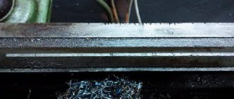
The service life of turning equipment largely depends on the proper functioning of the lubrication system of the units, the surface of which is in constant friction against each other. Timely lubrication prolongs the serviceability of machines, reduces their power consumption, reduces the load on parts, and reduces their wear. In addition, the use of high-quality lubricants has a positive effect on the quality of turning, efficiency, and allows maintaining the temperature of the units in a given range. Factors such as the health of the system and the choice of suitable oil are decisive.
Lubrication systems for lathe components
The operation of lubricating devices that deliver oil to the required point is based on the simplest laws of physics:
- Gravity, allowing oil to flow to the friction point on its own
- Capillary forces, which, through porous bushings and wicks, lift the lubricant to a certain height.
- The viscous friction force generated between the surface and the lubricant material itself prevents the latter from flowing down.
- Pressure. Used in manual lubrication systems such as piston pumps and oilers.
- Centrifugal forces causing oil to flow under pressure to surfaces.
- Inertia. Due to the capture of liquid by the rotating elements of the machine, its particles are scattered.
- The pressure difference that creates self-suction of oil through the mechanisms themselves.
Areas of use of turning equipment
Screw-cutting lathes vary in weight and size, which directly depends on the industry where they are used. They can produce short and long, thin and wide parts. These lathes can cut internal and external threads on parts. The heavier the part, the more massive the machine for processing it.
Light weight turning equipment is used:
- in experimental workshops;
- in instrument making;
- in the manufacture of watch movement parts.
This type may have a mechanical supply of blanks to the cutter, which allows for faster production of identical parts, if necessary, to produce them in small batches. For the production of piece products, this mechanism is not required, which will be reflected in the design of the lathe.
In the industrial production of threaded parts and tools, medium-weight machines are more often used. Their design contains many automatic systems, which, along with rotary mechanical parts, require preventive checks and debugging. Moving, twisting, rotating, cutting and drilling parts require regular lubrication.
Heavy weight turning equipment is used for more repetitive operations. On it are machined:
- shafts;
- turbines;
- wheels for trains.
Despite the small range of products and a small selection of operations, these machines cannot be called simple. There are also many components in its design that require constant care and monitoring. Lubrication and cleaning of parts becomes more difficult due to their heavy weight.
If you find an error, please select a piece of text and press Ctrl+Enter.
Manufactured by heavy industry, the 1K62 model lathe has long been familiar to metal processing specialists as a reliable and easy-to-use unit.
Known to most workers, the 1K62 type lathe is one of the popular models of equipment used for the manufacture of a wide variety of parts. Their distinctive feature is increased functionality, versatility and high reliability. This machine is still rated very highly among specialists in the processing of metal blanks.
Methods for lubrication of a lathe
1. Periodic manual lubrication - performed through technological openings that are closed during operation of the machine. To perform this, a syringe or oil can is used. A piston hand pump is used to deliver fluid to hard-to-reach places.
2. Drip or wick method - produced using drip or wick oilers by filling special containers. Of the latter, lubricant is continuously supplied to the surface of parts due to capillary forces.
3. Circulating lubrication - produced through the operation of a hydraulic pump, which supplies oil under pressure directly to the parts. The liquid drains naturally. The amount of lubricant supplied is regulated by special devices.
4. Crankcase method - produced by spraying oil with a fast-moving impeller or a gear immersed in a lubricant, connected to rotating parts of the equipment.
5. Combined lubrication - used in cases where the listed methods separately cannot provide optimal lubrication of mechanisms and parts.
Oil in a lathe performs the following functions:
- Protects mechanisms and parts from wear;
- Removes wear products from the working area;
- Removes heat;
- Reduces friction coefficient.
Types of oils for metalworking machines
When servicing equipment for metal turning, so-called industrial oil is used - a distillate petroleum product with low or medium viscosity. Its characteristic conditions of use are moderate pressure and thermal conditions, and you can buy it from any manufacturer. The main thing is compliance with GOST.
High-quality industrial oil for lubrication of machine tools has the following characteristics:
- Does not form foam;
- Does not form persistent emulsions with wear products;
- Resistant to elevated temperatures;
- Has high dispersing and washing properties;
- It has a stable chemical composition.
For industrial oils, the defining characteristics are:
- Density - has a greater effect on the properties of oils for hydraulic systems. Transmitting qualities decrease as the density of the liquid decreases.
- Viscosity is a parameter that directly affects the quality of the lubricant. It is the most important when choosing a lubricant for turning equipment. Depends on operating conditions, in particular on temperature. The higher the last indicator, the lower the viscosity.
- Flash point – affects oil consumption and waste. Essentially it is the ignition temperature of a liquid.
- Pour point – taken into account when storing liquid and transferring it.
- Ash content – degree of purification. The lower this indicator, the better the oil is purified.
- Acid number and sulfur content - the degree of purification from acids and sulfur.
To be sure which oil to pour into a particular lathe, its choice is made based on the manufacturer’s recommendations, which are necessarily indicated in the operating instructions.
Industrial oils for lubrication of lathes and drilling machines are divided into:
- And - without additives;
- IGP (alloyed) – with additives.
The following brands of industrial oils without additives are poured into the lathe:
- I-5A - used for lubricating mechanisms and components operating at high speed under light load, which do not require special anti-oxidation and anti-corrosion properties of the lubricant composition. At 40°C it has a kinetic viscosity of 6-8 mm2/s and a flash point of 120°C. In metal-cutting machines it is used to lubricate high-speed spindle units. Can be replaced with brands I-8A, ILS-5.
- I-8A is a similar brand to the previous one. At 40°C they have a kinetic viscosity of 9-11 mm2/s and ignite from 130°C. Can be replaced with brands I-5A, ILS-10, ILS-5.
- I-20A - used for lubrication of components operating at lower speeds and high loads, for example, sliding and rolling guides, gears. Viscosity 29-35 mm2/s and flash point from 180°C. Can be replaced with IGP-18 brand or another similar viscosity index.
- I-30A - in turning equipment it is mainly used for lubrication of the apron, drive shafts, slides, tool holder, and replaceable gears. Viscosity is 41-51 mm2/s and ignition occurs at 200°C. Can be replaced with brand IGP-30 or similar in viscosity.
- I-40A – Used for lubrication of gears. Viscosity 61-75 mm2/s and flash point from 200°C. Can be replaced with brand IGP-38 or similar in viscosity.
- I-50A - viscosity 90-110 mm2/s and flash point from 215°C. Can be replaced with brand IGP-38 or similar in viscosity.
1. Maintenance of the machine’s lubrication system by a turner consists of daily checking the oil level in the reservoir before starting turning work. If necessary, add liquid. When replacing, drainage is carried out through the plug. Before filling the tank, the latter is cleaned and washed with kerosene.
2. The apron mechanism has an automatic lubrication system with an individual pump. The oil level being filled is controlled by an oil indicator, usually located on the front side. The cross slide and carriage are lubricated at the beginning and middle of the shift until an oil film appears on the guides. Lubrication of the lead screw support bushings and guides during screw cutting operations is carried out with the uterine nut on.
3. The tailstock, lead screw and shaft supports are lubricated with wicks from the reservoirs. In the latter, oil must be poured until it flows out. Lubrication of the tapered axis of the tool holder is carried out daily at the end of the shift. In this case, the cutting head is removed.
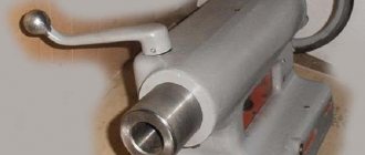
Tailstock of a lathe. Construction and repair of the tailstock
The device of the tailstock of a screw-cutting lathe
The general view and layout of the tailstock of a screw-cutting lathe is shown in Fig. 33.
The tailstock serves to support the workpiece during processing in the centers and represents a second support.
When drilling, the tailstock is connected to the caliper carriage with a special clamp and receives mechanical feed from it. The drill is inserted into the quill instead of the center.
The tailstock must satisfy the following conditions:
- under no circumstances move arbitrarily
- give the correct position of the center axis
- enable quick installation along the machine axis
- provide the ability to accurately position the workpiece on both center holes of the machine
- ensure reliable direction of the spindle (quill) of the tailstock and its clamping without disturbing the position of the axis
The stability and reliable position of the tailstock axis are necessary conditions for obtaining satisfactory results when machining on centers and eliminating the possibility of accidents due to the workpiece being pulled out of the centers. This depends on how the tailstock housing is secured to the frame.
The designs of tailstocks are very diverse, but their basic concepts have much in common. Therefore, knowing the basic structure of the tailstock of any medium-sized universal lathe, you can easily understand the design of the tailstocks of other lathes.
Let's look at the design of the tailstock of a lathe. The tailstock body of this machine, like most other types of machines, consists of two parts: the body itself 1 and the base (raft, bridge) of the tailstock 2.
The raft (bridge) is scraped along the frame guides, and the body is installed on its upper surface.
The planes of contact between the body and the raft are scraped so that the axis of the tailstock coincides in height with the axis of the machine spindle and is parallel to it.
Parallelism of the axes is achieved by scraping the vertical edge of the guide bead on the raft.
Lateral alignment of the axes is achieved by moving the body along the raft using a square-head screw and nut. The body is attached to the raft and at the same time to the frame using two bolts 4 and a lining 3. Achieving coincidence of the axes of the spindles of the headstock and tailstock by scraping the supporting planes of the headstock body requires a significant investment of time. Therefore, as a rule, during a major overhaul, the coincidence of the axes of the headstock and tailstock is achieved by boring the hole for the tailstock spindle. In this case, it becomes necessary to replace the tailstock spindle, which is finally machined along the outer diameter only after boring the tailstock body.
The tailstock spindle (quill) 7 is a hollow cylinder, the front edge of which is made in the form of a Morse cone into which a center 6 or drill is inserted, and a nut 9 is inserted into the rear edge. Using this nut and a screw 8 with a flywheel 10, the spindle can move along the axis . Key 5 protects the spindle from turning. The spindle is clamped with a handle, which has right and left threads at the end for clamping nuts. When the spindle is retracted completely into the tailstock, screw 8 with its end rests against the end of center 6 and pushes it out of the spindle body. Thus, in this design, knocking the center out of the cone is very convenient.
In heavy machines, the spindle does not have a nut, the cutting is done directly on the spindle, and the flywheel bushing is a nut. It is impossible to knock out the center from the end of such a spindle. Therefore, ordinary centers are not suitable for such spindles; the centers should be threaded. A nut is screwed onto the thread, with which the center can be pressed out, or flats are made on the centers, which make it possible to turn the center with a key and thereby release it from the socket. The use of simple centers on these machines should be prohibited, since they are pressed in and can only be knocked out by hitting a sledgehammer or heating the spindle with blowtorches. This leads to damage to the spindle cone.
When processing flat cones, it is necessary to shift the center of the tailstock in the transverse direction. For this purpose, the tailstock body and the base are connected to each other by a transverse key. The transverse displacement of the headstock body relative to the base is made by screws and a nut.
Tailstock of lathe 1k62. Assembly drawing
Tailstock of a lathe. Assembly drawing. View enlarged
Tailstock of lathe 16k20. Assembly drawing
Tailstock of a lathe. Assembly drawing. View enlarged
Repair and restoration of the tailstock of a lathe
When repairing the tailstock, the accuracy of the mating surfaces of the bridge with the frame and the body, the accuracy of the body opening and the height of the centers of the front and rear stock are restored, the quill, feed screw and other parts are repaired or remanufactured.
The most labor-intensive operations are to restore the accuracy of the hole in the body for the quill and restore the height of the centers.
The hole for the quill in the body is repaired by lapping, boring, followed by finishing, and using acrylic plastics.
Laps usually repair lightly worn holes. In this case, the height of the centers is restored by placing compensation pads on the guides and a new quill is made.
When repairing by boring, the height of the centers is simultaneously restored. After boring, the hole is usually finished with laps, and the quill is made of a larger diameter.
Acrylic plastics restore both the precision of the quill fit and the height of the centers. In this case, the quill is not manufactured, but repaired.
This repair method is the most effective, since it requires 3-5 times less time and money than the first two methods.
The two options for repairing the tailstock discussed below clearly confirm the profitability of repairs using acrylic plastics, in particular styracrylic of the TSh brand.
Repair of the tailstock housing and bridge without the use of acrylic plastic
The repair sequence is as follows:
- The surface of the 9th body is scraped (Fig. 60). The number of paint prints must be at least 10 on an area of 25 X 25 mm
- The surface 10 of the bridge 8 is milled and the cover is installed with glue or screws. If the bridge protrusion is tightly coupled with the housing groove, this operation is not performed
- The surfaces of the bridge mating with the hull are scraped (along the hull). The number of spots when checking for paint is at least 10 on an area of 25 X 25 mm. The protrusion of the bridge must fit tightly into the groove of the housing (without play)
- The surfaces of the bridge are scraped along the frame guides. The number of paint prints is 10-15 on an area of 25 X 25 mm. At the same time, when scraping, the surface mating with the body is ensured to be horizontal with an accuracy of 0.05 mm per 1000 mm of length. The check is carried out using a level installed on surface 9 along and across the frame guides. The frame is installed and leveled, while the plane for attaching the feed box must be positioned strictly vertically.
- Attach the bridge to the hull
- The bead rod is secured in the spindle of the machine headstock. The axis of the bead rod at the point where the cutter is attached must be 0.05 mm higher than the normal position of the spindle axis, for which: the measuring rod of the indicator, mounted on the machine support, is brought to the upper generatrix of the bead rod (at the point where the cutter is attached) and this position is fixed; loosen the front bolts securing the headstock (the spindle axis is already aligned parallel to the frame guides), use a lever to slightly raise the front part, place 0.02-0.05 mm thick foil under the front ends of the guides and secure the headstock to the bed; bring the indicator to the upper generatrix of the bead rod and notice its new position, in which the axis of the bead rod should be located 0.05 mm above the spindle axis.
- Install the tailstock in front of the caliper carriage and apply a weight for rigidity
- Boring the hole for the quill in the tailstock body (in 2-3 passes), spindle rotation speed 250 rpm; feed 0.1 mm/min. In this case, the surface finish must be no lower than V5, taper - no more than 0.02 mm, ovality - no more than 0.01 mm.
- Grind the hole in the body using an expanding mandrel mounted in the spindle and sandpaper. Spindle rotation speed 500-800 rpm, feed 10-15 m/min. Surface finish V7, taper - no more than 0.02 mm, ovality - no more than 0.01 mm
- The hole in the body is fine-tuned using a cast iron lap. Spindle rotation speed 200-300 rpm, feed - 5-8 m/min. In this case, a surface cleanliness of V 8 is achieved, the taper should be no more than 0.01 mm, and the ovality should be no more than 0.005 mm.
- Remove the foil from under the headstock guides and secure the headstock to the bed. The tailstock is assembled with a newly manufactured and fitted quill. The movement of the quill should be smooth, without backlash. The clamp should ensure reliable fastening of the quill.
- Check the position of the quill in relation to the bed guides and the coincidence of the centers of the front and rear stock, in accordance with the technical specifications in accordance with GOST 42-56.
The considered tailstock technological process is widely used in many factories, despite its significant labor intensity.
Restoring the tailstock with acrylic plastic
Restoring the tailstock with acrylic plastic is very simple and effective, since operations on precise boring and finishing of the housing hole are eliminated and it is possible to preserve the old quill. Bridge repairs are carried out in the same way as for repairs without acrylic plastic.
The technological process of restoring the hole in the tailstock housing includes the following operations:
- The hole for the quill in the body 4 of the tailstock (Fig. 60) is bored on a boring or lathe, and a layer of metal equal to 2-3 mm is removed. The cleanliness of the processing must correspond to V 1, taper and ovality are allowed no more than 0.5 mm.
- In the spindle 2 of the headstock 1 of the machine, the axis of which is adjusted to be parallel to the bed guides, a hollow mandrel with a plug 7 is installed. The outer diameter of the cylindrical part of the mandrel corresponds to the outer diameter of the repaired quill and has a size 0.01 mm larger than the quill. The mandrel is installed eccentrically relative to the spindle axis by 0.07-0.08 mm. To do this, a gasket shaped like a truncated cone with a thickness of 0.07–0.08 mm is placed in the conical hole of the spindle before installing the mandrel. The material for the gasket is paper or foil. The shape of the gasket (truncated cone) ensures uniform runout at both ends of the mandrel.
- By rotating spindle 2, check the runout of the mandrel, which should be no more than 0.15-0.18 mm, and install the spindle so that the generatrix of the mandrel with the largest positive deviation is located above the spindle axis. This arrangement of the mandrel ensures that the difference in height between the centers of the headstock and tailstock (0.05-0.07 mm) is established in accordance with the requirements of the technical specifications.
- In the body of the tailstock 4, three holes with a diameter of 6-8 mm are drilled above the hole for the quill; holes are located in the middle and along the edges of the body
- Degrease the bore of the housing and dry for 15-20 minutes until the solvent has completely evaporated.
- A thin, even layer of soap is applied to the mandrel, the tailstock body is installed and bolted to the frame.
- The hole for the quill (the space between the mandrel and the headstock body) is sealed with rings and plasticine 6; The holes of the quill fastening devices are also sealed, and three funnels 3 and 5 are installed from plasticine above the three drilled holes.
- Prepare an acrylic solution and pour it into the middle funnel. Filling is completed when the mass of styracrylic partially fills the outer funnels
- The flooded tailstock is kept in place for at least 2 hours at a temperature of 18-20 ° C
- They move the tailstock, protect the body from plasticine and tides of plastic, make lubrication grooves, drill holes, chisel the keyway and assemble the tailstock
Tailstock quill repair
This process involves grinding the outside diameter and restoring the taper bore by installing an expansion sleeve.
The compensation sleeve (Fig. 61, a) has a cylindrical shape on the outside and a cone on the inside. The bushing is often made from case-hardened steel, with the cone hardened to HRC 58-60. The wall thickness of the bushing near the largest diameter of the cone is taken to be 2 mm or more (depending on the diameter of the quill).
The outer diameter of the bushing is made according to the bored hole of the quill with a gap of 0.05 mm, the cleanliness of the machined surface is V5-V6.
The bushing is glued into the quill and after hardening (after 24 hours), the conical hole is ground.
As an example, we give the technology for restoring the tailstock quill of a screw-cutting lathe model 1E61, which consists of two stages:
- manufacturing an expansion sleeve (Fig. 61, a)
- quill repair (Fig. 61, b)
- The sleeve is machined with technological allowances, Morse taper No. 3, for grinding the interference is 7-8 mm, not counting the allowance of 5 mm. Cement to a depth of 0.8-1.2 mm. Remove technological allowances, leaving 1 mm per side. Kalat, HRC 58-62. The outer diameter and ends are machined according to the drawing (checked on a cone mandrel).
- Bore a hole in the quill Ø30A to a length of 90 mm (check for runout with an accuracy of 0.05 mm, finish V 5). Install the bushing with epoxy glue and keep it for 24 hours at a temperature of 18-20° C. Insert plugs on both sides, center them with an accuracy of 0.02 mm, grind the quill along the top to size and trim the front end, chamfering. Grind the outer diameter to size. The lubrication groove is milled according to the sketch. The numbers are engraved according to the sketch. Remove the plugs. Then the quill is aligned with an accuracy of 0.01 mm, the Morse taper No. 3 is ground on the cork and the front end is clean.
A quill repaired using this technology has increased wear resistance of the tapered hole, and the cost of repair is significantly lower than the cost of manufacturing a new quill.
Repair of the tailstock bridge of a screw-cutting lathe 1k62
Boring the tailstock of a screw-cutting lathe
Lapping the tailstock of a screw-cutting lathe
Adjusting the tailstock of a lathe
Literature
- Borisov G. S. and Sakharov V. L. A short reference book for a shop mechanic. M., publishing house "Machine Building", 1966.
- Gelberg B. T. Factory experience in modernizing machine tools. Lenizdat, 1960.
- Gelberg B. T. and Pekelis G. D. Issues of technology and organization of equipment repair. M., Proftekhizdat, 1960.
- Gelberg B. T. and Pekelis G. D. Repair of industrial equipment. M., publishing house "Higher School", 1967.
- A unified system of scheduled preventive maintenance and rational operation of technological equipment of machine-building enterprises. M., publishing house "Machine Building", 1967.
- Klyagin V.N. Technical conditions for the repair of metal-cutting machines of normal accuracy. M., publishing house "Machine Building", 1967.
- Pekelis G.D. and Minkin A.S. Repair of metal-cutting machines. Lenizdat, 1962.
- Pekelis G. D. and Gelberg B. T. Restoration and strengthening of process equipment parts. M., publishing house "Machine Building", 1964.
- Pekelis G. D. and Gelberg B. T. Mechanization of metalwork and repair work. M.-L., publishing house "Machine Building", 1967.
- Pekelis G. D. and Gelberg B. T. Repair of metal-cutting machines and forging and pressing equipment according to standard technological processes. M., publishing house "Machine Building", 1967.
- Pekelis G. D., Gelberg B. T. and Gordin Yu. N. Centralization and specialization of equipment repair in a production association, LDNTP, 1967.
- Pronikov A. S. Calculation and design of metal-cutting machines. M., publishing house "Higher School", 1967.
- Sheingold E. M., Nechaev L. N. Technology of repair and installation of industrial equipment. M.-L., publishing house "Machine Building", 1966.
- Shchebrov V. M. Repair of machines and mechanisms. M., publishing house "Higher School", 1964.
- Yakobson M. O. Machine tool technology. M., publishing house "Machine Building", 1968.
Useful links on the topic
Catalog directory of metal-cutting machines
Passports and manuals of metal-cutting machines
Directory of woodworking machines
Buy a catalog, directory, database: Price list of information publications
Pekelis G.D., Gelberg B.T. L., "Mechanical Engineering". 1970
stanki-katalog.ru
1M63 grease
Description of work
Circulating gearbox lubrication system
The system includes a reservoir 9, a vane pump 14, a plate filter II and an oil distributor 12. The vane pump is driven by a gear transmission from the first shaft of the gearbox. The oil supplied by the pump passes through the filter and enters the oil distributor, from which it flows through tubes to lubricate the spindle bearings, to the clutch lubrication pan, and to lubricate the electromagnetic brake clutch and gears. After passing through the lubricated parts, the oil collects at the bottom of the gearbox. Monitoring the presence of lubrication in the system and its level in the gearbox is carried out using oil indicators 10 and 8.
Figure 1 - machine lubrication diagram
Circulating apron lubrication system
The system includes a reservoir 23, a plunger pump 17, an oil distributor 21. The plunger pump is driven by a cam mounted on the rack and pinion gear shaft. The oil is supplied by a pump to the oil distributor, from which it is supplied to lubricate the apron parts. The presence of lubrication in the system and its level in the apron are monitored using oil indicators 20 and 25. The operation of the plunger pump is monitored during accelerated movements of the caliper.
Circulating sprinkler feed box lubrication system
The system includes a reservoir 1, a plunger pump 3 and a tubular sprinkler oil distributor 6 located in the upper part of the feed box. The plunger pump is mounted at the bottom of the feed box and is driven by an eccentric on the first shaft of the feed box. The oil is supplied by a pump to a tubular oil distributor, from which it is supplied to lubricate the feedbox parts. Monitoring the presence of lubrication in the system and its level in the feed box is carried out using oil indicators 5 and 4.
Wick lubrication system for the rear supports of the lead screw and the lead shaft
The system includes a bath 22, closed with a lid. The oil from the bath travels through the wick to the lubrication points.
Wick lubrication system for replaceable gear tracks
The system includes a bath 7 and a tray.
The oil flows through the wick to the lubrication points, and through the hole in the pan it enters the feed box.
Lubrication system for longitudinal movement guides of the caliper and lead screw
The system includes a reservoir 18 and a plunger pump 19 with a distributor. The plunger pump is periodically actuated manually by axial movements of the pump activation handle.
ATTENTION! If there is no oil in the oil indicators for controlling the operation of the vane and plunger pumps, you cannot operate the machine.
Instructions for installation and operation of the lubrication system
Before putting the machine into operation you must:
- Fill reservoir 9 (see Fig. 9) of the gearbox through hole 13 with industrial oil I-30A in an amount of about 20 liters. The oil level is monitored using oil indicator 8. If the oil supply in oil indicator 10 decreases, turn the plate filter handle 2-3 times through hole 13 to clean it. When starting to operate the machine, it is advisable to clean the filter daily; the filter reservoir sump should be cleaned when changing the oil;
- fill tank 23 of the apron through hole 26 with industrial oil I-20A in an amount of about 3 liters. The oil level is monitored using oil indicator 25. When operating the machine for a long time using a transverse slide, it is recommended to periodically make 2-3 quick movements of the slide along the frame to ensure lubrication of the apron. The use of oils with high viscosity leads to delayed disengagement of the clutch discs, as a result of which overtravel of the caliper occurs after it is turned off or the movement is reversed;
- fill reservoir I of the feed box through hole 15 with industrial oil I-30A in an amount of about 5 liters. The oil level is monitored using oil indicator 4;
- fill the caliper guide lubrication reservoir 18 through hole 27 with industrial oil I-30A in an amount of about 0.2 liters. Level control
- oil is produced according to the mark on the rod of the hole plug 27. To increase the uniformity and smoothness of the movement of the caliper, which is especially important during thread-cutting work, it is recommended to use VNII NP-401 GOST 11058-75 oil as a lubricant. It is recommended to periodically, at least 4-5 times per shift, make 2-3 quick movements of the caliper, after manually making 3-4 double strokes of the pump plunger before each movement;
- fill the lubrication points I-UP with oil in accordance with table. 8. Lubricate the surfaces of the lead screw, lead shaft and bed guides with industrial oil I-30A;
- pour industrial oil I-30A into bath 7 in an amount of about 0.3 liters and into bath 22 - 0.2 liters;
- Fill the oil caps of replaceable gears with synthetic grease according to GOST 4366-76. Oil caps after filling and installation: tighten 1.5-2 turns.
- When the machine is operating, you should monitor the oil level using oil indicators 4, 8, 25 and the rod installed in hole 27. The presence of oil supply is monitored using oil indicators 5, 10, 20.
- The oil change must be done the first time after 10 days of operation, the second time after 20 days, then every 40 days.
- To drain the oil when changing it, drain holes 2, 16, 24 are provided.
- The NK-50 grease in the electric pump bearings should be replaced at least once every 6 months.
- ATTENTION! To lubricate the machine, only filtered oil should be used.
Table - List of lubrication points
Scheduled preventive maintenance - PPR
Scheduled preventive maintenance is a set of measures to maintain the machine in working condition while maintaining its technical characteristics at the level corresponding to those specified by the manufacturer in the machine’s passport.
In accordance with the maintenance schedule drawn up based on the operating mode of the unit, the following is carried out:
- Maintenance – cleaning, lubrication, filling and changing oils.
- Replacement of worn parts and dull cutters.
- Washing the entire machine or its individual components.
The preventive maintenance plan should include:
- preventative repairs;
- current (small and medium) PPR;
- capital PPR.
Between-repair maintenance
Compliance with the operating requirements stated by the manufacturer refers to:
- equipment control mechanisms;
- workplace barriers;
- maintaining lubricating devices and reservoirs clean, monitoring their filling with lubricants.
- troubleshooting minor problems;
- adjustment of adjustable mechanisms.
All of the listed types of maintenance do not require much time, which allows them to be carried out during technological, lunch, and inter-shift breaks. It is better to schedule equipment readjustment on weekends. For high-level turners with permission to carry out a certain type of adjustment work, this will not be difficult. In other cases, it is necessary to add this type of minor repair to the to-do list for the workshop repair and commissioning team.
Read also: Microphone amplifier circuit for lm358
PPR of automatic machines is carried out daily, after the end of the shift. When the workshop operates in 2 and 3 shifts, they are serviced once every 8 hours. In workshops with a shift work schedule, there must be a repair and adjustment service consisting of:
- mechanics;
- lubricants;
- locksmiths;
- electricians;
- saddlers and other specialists of a narrow profile.
This should ensure high quality of each unit individually, and the machine as a whole.
To watch online, click on the video ⤵
#20 -Changing the oil in a lathe. What and how to pour? More details
How to properly LUBRICATE a 1k62 lathe. More details
The oil saga continues. Lathe 1k62 More details
What kind of oil to pour into the machine. More details
An oil fountain appeared. Headstock 1k62 More details
What oil to use to lubricate the machine lubrication system 1a616 Read more
Lathe 1K62 - Headstock, oil drain, cleaning. More details
A short review of the 1k62 lathe Read more
Lathe 1K62 - How to make wick lubricant Read more
How to mix oil and water. Changing the lathe oil Read more
About the 16k20 lubrication system Read more
How to cut threads on a 1k62 lathe Read more
Checking the machine upon purchase. №1 Read more
✅ Grooving brake discs / brake disk groove / الحز من الأقراص Read more
Homemade door handles made of epoxy resin. Epoxy Door Handles More details
Eternal oil level peephole Read more
LATHE .Changing the oil, cleaning the guitar/TV 4 oil changes,cleaning the guitar More details
1-3 Lathe Maintenance - Reboot with Improvements Read more
Brief history of the series
- The first screw-cutting lathes with a gearbox were produced and called DIP 200,
- DIP 300 and so on. The letters meant “Catch up and overtake”, and the numbers meant the height above the bed.
- ENIMS adopted a unified system of machine symbols. According to the DIP 200 system, it began to be called 1D62, and accordingly its modifications changed their names.
- Soon the first DIP 200 models appeared, called 1D62,
- 1D62M. These models were then replaced by a newer one - 1A62. The 1A62 was produced for several years, after which it was replaced by the 1K62, which was produced for another eighteen years. Modifications were produced by 1K62.
- Then the 16B20P entered production, which was a transitional model between the two machines.
- After another six years, the first 16K20 were produced. The machines gradually began to produce less and less. They began to be modified, but the modifications were not long-lasting.
- Seventeen years after the first 16K20 they were replaced by machines of the MK series: MK6046, MK6047.
How does the machine lubricate automatically?
Lubrication of a screw-cutting lathe, or rather its moving parts, must occur constantly during operation. The supply of lubricants to the rotor is indicated by the rotating disk on the spindle head. Its rotation should begin within a minute after starting the equipment. This time should be enough for the gear pump, connected by a belt drive to the main engine of the unit, to supply oil to the reservoir. The lubricant will reach the engine bearings and oil distribution trays through a strainer with a magnetic liner. The system is closed - flowing into the spindle head, the oil again enters the reservoir, where it is cleaned of debris by a filter and again ends up on the moving parts.
Intermittent movement or stopping of the disk indicating the flow of lubricant to the parts of the screw-cutting lathe indicates that the filter is clogged or there is not enough lubricant in the system. In this case, the machine must
- disable,
- cut off the power
- remove the filter,
- wash it with kerosene,
- check the lubricant level in the reservoir,
- add oil if necessary,
- insert the filter into place and start the unit.
How to remove the filter
The mesh filter consists of several elements. To get it out of the tank, which serves as the filter housing, you need to disconnect the hoses from it, unscrew the bottom nut, and remove the filters along with the plastic frame.
Attention! Filters can only be washed in kerosene. Under no circumstances should they be cleaned with air. This method of cleaning can lead to the immediate loss of the mesh’s working qualities. Strong air pressure deforms its cells.
Scheduled maintenance with mandatory filter washing is carried out in accordance with the instructions in the technical data sheet of the equipment.
Purpose and scope of application of a metal screw-cutting lathe
The 1K62 lathe is universal and is used for finishing and semi-finishing turning tasks. They cut left and right threads: metric, inch.
Used for processing hardened workpieces because the spindle provides rigidity to the machine. It produces high-quality cuts with carbide tools due to the large speed range of 1K62.
The device is frontal and it processes short workpieces of large diameter. The machine processes flat cones, because its rear beam can move.
Main varieties and explanation of modifications
The first 1K62 was released on and went through a long journey, with many modifications.
The main varieties were: 1K625, 1K620, 1K62B. The modifications have decodings, each number and letter has a meaning:
- The number 1 means that the machine is a lathe.
- The letter K indicates the generation of the device.
- The number 6 indicates that the machine is a screw-cutting lathe.
- Number 2 indicates the height of the centers.
- The numbers 25 at the end indicate the maximum diameter of the workpiece above the caliper.
- The numbers 20 are the height of the centers above the bed.
- The letter B is the value of the change in the main model.
This is what the main modifications look like, their decoding 1K62.
Specifications
The main technical characteristics are:
- The machining diameter above the caliper is two hundred mm.
- The distance between centers is one thousand mm.
- Electric motor power - 10 kW
- The weight of the machine is 3035 kg.
- The transverse displacement of the housing is approximately fifteen mm.
Main settings
The main parameters are called: the distance between centers, which is a thousand millimeters, the weight of the machine is two tons.
The spindle speed limits in the forward direction reach 2 thousand revolutions per minute, in the reverse direction up to 1900 revolutions per minute. The diameter of the cartridge is 250 millimeters.
Spindle
Spindle is a shaft that has right and left turns of rotation. The spindle is installed to hold tools as well as workpieces. Consequently, a clamping chuck or other elements are attached to it. It depends on the device.
Caliper and feed
The support is designed to move, fixed in the tool holder, along and across the spindle axis. It consists of three main units - the carriage, the cross slide, and the tool slide of the caliper. In technical literature they may be called differently.
The feed box is used to switch the rotation speed of the lead screw and shaft, that is, to select the feed speed of the cutter along the spindle axis. A gearbox is usually located inside the box.
The gearbox is made of gears that shift. The input feed shaft receives torque from the spindle. Before doing this, it goes through the guitar.
Cutting slide
The cutting slide is one of the main components of the caliper. They are installed at an angle to the center line of the machine centers. The cone is processed by manually moving the cutting slide. This method allows you to process internal and external cones with any slope angles.
Tailstock
The headstock is a unit that is used in many metal-cutting machines. The headstock accurately supports and moves the part relative to the tool that cuts it. Usually it is located, mounted on the frame. There are three functions:
At the back, the assembly has a tapered hole for installing the center. The center supports the workpiece and is used to secure the tool.
Electrical equipment
Electrical equipment is intended to set units and mechanisms in motion, automatically control them, and monitor their condition. The performance and reliability of units depends on electrical equipment.
Dimensions and weight
The unit has dimensions and weight:
- The motor power for fast movements of the caliper is from 0.75 to 1.1 kW.
- Cooling pump power - 0.12 kW.
- The overall dimensions of the machine are two thousand eight hundred twelve millimeters in length, one thousand one hundred sixty-six in width and one thousand three hundred twenty-four in height.
- The weight of the machine is three thousand thirty-five kilograms.
List of machine controls 1k62 (see Fig. 5)
Position in Fig.5
Controls and their purpose
2 5; 9 7 8 10 11 12 13 15 16 17 18 20 22 24 25 26 27 29, 38 32 34 35 36 39
Handle for selecting the type of thread and type of work (thread or feed) Handle for setting the spindle speed Handle for setting the normal, increased thread pitch and position when dividing into multi-start threads Handle for setting the right and left thread and feed Handle for manual transverse feed of the support Handle for rotating and fastening the cutting head Local lighting switch Screw for fastening the carriage for end robots Handle for manual movement of the upper part of the support Button for turning on the fast movements of the carriage and support Handle for controlling the strokes of the carriage and support Handle for fastening the tailstock quill Cooling pump switch Input switch Signal lamp for turning off the power supply Handle for attaching the tailstock to the frame Travel handwheel tailstock quills Bolt nut for additional fastening of the tailstock Clutch control handle Lead screw nut activation handle Push-button station for turning on and off the main drive Handwheel for manual movement of the carriage Button for turning off the rack and pinion gear when cutting threads Handle for setting the feed rate and thread pitch
Fig. 5 – Location of controls and places of plates of the 1K62 machine
General design and operating principle
The design features regulatory bodies that are familiar to experts, and a simple control scheme is used. The model consists of nodes:
- bed;
- front, rear cabinets;
- headstock;
- chuck;
- tailstock;
- tool holder;
- apron with caliper feed mechanics;
- drive shaft;
- gearbox.
The design is designed for high vibration resistance and rigidity. The base is pedestals, and to increase their rigidity, vertical ribs are used on the walls.
On the left side of the unit there is a headstock, inside it is a gearbox, a spindle with a chuck. On the right side is the tailstock. The caliper can move in different directions due to the apron.
Photo and description of the device
We have just reviewed the general design of the device, and now, along with pictures, the devices of the unit, their properties, features, and meanings in the mechanism will be described in detail.
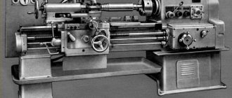
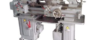
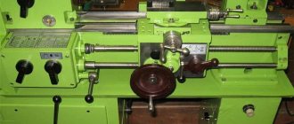
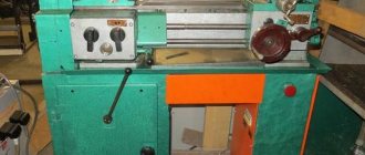
General form
In this picture you can admire the general view of the screw-cutting lathe. The components and various devices discussed earlier are immediately visible.
The weight is more than two tons, and the engine power reaches ten kW. The next picture shows a more detailed drawing, which shows the nodes and their location.
Drawing
This is a general design drawing. It shows all the main components. They will be reviewed one by one very soon. In the upper left corner is the front headstock, in the lower left corner is the gearbox and engine unit.
To the right of the front headstock the chuck is visible, and to the right of the chuck there is a guard, a carriage. Under the numbers 12, 13 in the middle there is a switch, an apron.
Top right - caliper, handle release mechanism, cooling, tailstock, electrical equipment, bed.
Location of controls
The picture shows all the controls and their locations. There are twenty-two organs in total. From the simplest to the very difficult to manage and study.
They control all the mechanisms, thanks to them the unit works and performs tasks. They will not be considered, however, in order to work with the machine you need to know them to avoid accidents.
Kinematic diagram
The photo shows a kinematic diagram, that is, a conventional image of the unit, which shows the connection between the elements of the mechanism that transmit movement. The diagram helps to better understand the design of the structure, repair it correctly, and make correct calculations.
Each element in the diagram has its own designation. The symbols must be learned in order to understand the diagram. The shaft is indicated by a straight line, the lead screws by a wavy line, and so on.
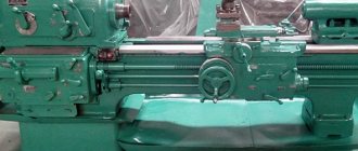
Headstock
Previously, the rear one was considered, but there is also a spindle one. It is best seen in the picture above. The design is a unit of grinding machines.
It consists of a supporting spindle, which imparts rotational motion to the grinding wheel. The purpose of the mechanism is to place the spindle and its drive mechanisms.
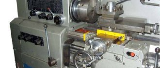
Speed and feed switching device
The gearbox is the main part of the machine spindle drive, designed to transmit movement from the electric motor and change the rotation speed. Typically, the mechanism is mounted in a separate housing and connected by transmission to the spindle.
The feed box provides a large number of feeds in the machine. The second box helps her in this because it changes the speed. The feed mechanism is activated by clutches - friction, cam.
Apron
The picture above shows the apron of the turning unit. The apron converts the rotational movement of the lead screw and roller into the translational movement of the caliper along the frame guides.
The mechanism is usually attached to the front end of the caliper carriage. It has four jaw clutches. Clutches allow the carriage and caliper to make forward and reverse movements.
The apron has a blocking device that prevents the simultaneous activation of longitudinal and transverse feeds.
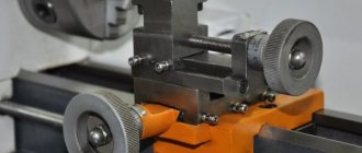
Caliper
The caliper shown is 1K62. The support is designed to move, fixed in the tool holder of the cutter along, across the axis of the spindle.
It consists of three main units - the carriage, the cross slide, and the cutting slide. In textbooks and books, nodes may be called differently, but they always perform the same functions.
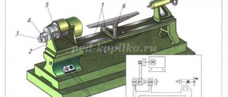
Tailstock
Above is a design called a tailstock. It serves to support the workpiece during processing in the centers; it represents the second support of the unit.
During drilling, the mechanism is attached to the carriage of the caliper to obtain mechanical feed. The mechanism cannot move arbitrarily; it must give the correct position of the center axis.
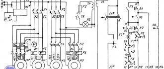
Electrical circuit diagram
At the top is the electrical circuit diagram. Each unit has this circuit. It shows the main components, parts, and current values.
Without this circuit, the breakdown of the device will be fatal, because it will be impossible to repair it without it. The diagram is most likely in the machine's passport.
Design Features
The design features of 1K62 include the versatility of its functionality and well-organized workspace. The ease of setting up the operating modes of the machine is especially noted.
The increased rigidity of all its working units is ensured by the use of heavy-duty bearings in the design. Due to the significant drive power on the 1K62, it is possible to process workpieces that have undergone long-term hardening.
Please note: The design of the bed provides the ability to change the position of the rear beam, allowing you to grind cone-shaped parts.
The beam itself is connected to the lower plane of the support with a special lock, which expands the range of drilling operations. The main structural components of this product include:
- A bed with two cabinets located at the edges.
- Two headstocks (front and rear placement).
- Caliper with tool holder and apron mechanism.
- Gearbox (Gearbox).
Let us next consider the organization of the workplace.
Workspace dimensions
The characteristics of the 1K62 workplace are as follows:
- the height of the frame with superstructures is one and a half meters;
- the total length of the base is from 2.5 to 3.5 meters (with a width of 1.2 meters);
- the permissible size of the part placed above the support is up to 22.4 cm, and above the bed - up to 43.5 cm
- permissible incisal section - within 2.5 cm;
- the maximum size of the blank fixed during processing is within the range from 75 cm to 150 cm;
- through size (diameter) of the shaft – 5.5 cm;
- free movement of the working carriage – up to 1330 mm.
Under certain operating conditions of machine tool equipment (when fixing a workpiece in a chuck, in particular), the weight of the processed blank can reach 300 kg. When installing workpieces in a centered position, its weight can reach 1300 kg.
Headstock and tailstock
The main purpose of the headstock is to provide the specified parameters for shaft rotation in various operating modes when performing the entire range of work operations. Switching elements for replaceable gearbox gears are also located here. The mechanisms located in it allow:
- make threads with a pitch that is a multiple of 4 and 16 units; in this case, the gear ratio increases by 8 and 32 times, respectively;
- provide right and left cutting;
- prepare threads in multi-start mode (from 2 to 60 starts).
The speed shift knob in this unit allows you to set one of 4 possible ranks of shaft rotation speed in accordance with the designation printed on it.
The tailstock supports the metal part in a centered machining mode, creating a second support point. When performing a drilling operation, it is connected to the caliper carriage by means of a special clamp, thereby providing mechanical feed from it. In this case, the tool itself is inserted into a special quill.
Model support and apron mechanism
The working mechanism of the apron with the couplings on it provides both forward and reverse strokes of the caliper and the working carriage. To control their movements, a special handle is provided on it. In addition, the apron is equipped with a locking mechanism that does not allow working with two feeds at once (longitudinal movement and transverse shift). A safety clutch is also located here, which is triggered if the apron is overloaded.
The amount of clearance (gap) in it is set during the factory settings of the machine. In case of repair, it is adjusted with a special screw located at the bottom of the apron at the end of the base of the uterine nut.
Read also: Dehumidifier for compressor from fire extinguisher
Feed and speed box
The gearbox ensures that the required rotation speeds of the main working shaft are set in a wide frequency range. This feature allows you not only to grind workpieces, but also to make thread cuts of five types on the machine (in different speed modes).
To control the amount of feed when preparing threads, the gearbox is equipped with a special handle with several positions. If it is necessary to cut a thinner thread, it is installed in a position where the lead screw is connected in a direct manner (bypassing the feed box).
To implement the “Fast movement” mode, it has a special overrunning clutch mounted on the output shaft.
Lubrication system 1K62
The main components and mechanisms of the gearbox, as well as all bearings included in its composition, are lubricated by automatic supply of oil from a reservoir located in the lower area of the headstock support. It is sucked from the container using a separate pump driven by an eccentric cam . After this, the oil is driven through a system of tubes through the filter, and then enters the headstock bearing (on the spindle and on the tray).
Further, under its own power, it lowers to gear units, movable bushings and other points to be lubricated. The rear bearing receives lubricant from an additional reservoir equipped with a felt wick.
Electric scheme
The electrical equipment of the machine contains the following mandatory components:
- fusible fuse inserts;
- a set of switches for various functional purposes;
- switching elements of power circuits (relays and contactors);
- illuminators (light bulbs);
- step-down converter 380/220 Volt and rectifier elements.
In addition to all of the above, the electrical part of the machine includes the main drive electric motor (M1), as well as three-phase high-speed motors and a cooling pump.
Additional information: The hydraulic unit motor (M4) is connected to the structure through a special plug connector.
This motor is an auxiliary one, working in conjunction with the hydrocopier device connected to it (in the figure above it is designated as M4*).
Kinematic scheme
To understand the relative location and interaction of the unit components, as well as its individual parts, it is important to study the kinematic diagram (figure below).
The easiest way to do this is to look at the passport of the 1K62 unit, which describes in detail not only the structure of the machine, but also the operating procedure of all mechanisms. Having become familiar with the intricacies and features of the design, the operator will be able to effectively use all its functionality.
Rules of operation and care
There are rules for caring for the unit so that it does not break down and is always ready for use. The equipment must be regularly inspected and checked for damage.
Engine operation is determined by sound. After starting, listen. If there are no extraneous sounds, oil is supplied, then the engine is working. If there are extraneous sounds, you need to disassemble the mechanism and find out the reason.
Care must be taken to ensure that the safety shield is holding the workpiece. Even if there is a minor malfunction, you must stop working and take the parts for repair.
From time to time, clean pipes and equipment, change cutters so that the load on the engine is less.
Daily care
The most reliable care for a lathe is to prevent damage to it. Preparation for the next work shift should be carried out immediately after finishing work and disconnecting the machine from the power supply. At this stage of maintenance, the following operations are performed:
- Chips and other technical debris are swept away from the surface.
- It is necessary to dissolve oil and dirt with kerosene and wipe dry with a rag.
- To avoid corrosion, all parts that do not have a paint coating are lubricated with oil.
- The oil cans are filled with grease.
Before starting a shift, it is necessary to check the presence of lubricant and inspect the equipment for damage or loose parts. During work, it is necessary to observe safety precautions when working with turning mechanisms - this will minimize injuries in the workplace and reduce the risk of equipment breakdown. During work you must:
- The use of protective screens, which will avoid clogging the lathe with metal shavings and small abrasive particles that arise during processing of the part.
- Timely replacement of drilling and cutting parts.
- Control over the reliability of fastenings of cutters and drills.
- During operation, do not allow the formation of long chips, which, if wound around the rotating parts, can damage the mechanism.
- You can turn on the machine only after the cutter is lowered onto the blank, in the place specified in the drawing.
Video covering basic maintenance principles.