provides a wide range of services in the field of repair of lathes. All work is carried out by professionals with extensive experience, who are well versed in all the nuances of repairing the hydraulic, mechanical, electronic and electrical parts of the device.
Today we carry out:
- repair of CNC lathes;
- repair of universal type screw-cutting lathes.
Our craftsmen will professionally carry out planned, routine or major repairs of turning equipment, and will do this in the shortest possible time, using reliable spare parts, components and consumables.
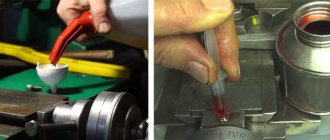
Overhaul of the electrical circuit of a lathe
Hello. I have been doing major repairs of lathes for several years. Several other people work with me, they have different responsibilities. My field of activity is electrical.
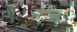
Mostly machines manufactured in the USSR, 1960-1980. There are a lot of modifications of machines, even with the same name, depending on the year of manufacture and the plant.
Sometimes you have to completely change all the parts of the circuit, including motors and wires, not to mention starters and buttons. It depends on the amount that the customer is willing to pay and the condition of the machine - sometimes it is enough to change the input circuit breaker and the burnt contacts, and the machine is ready.
Since some clients are not rich, we have to compromise, do things cheaper, and cut back on some functions. At the same time, I try to immediately explain what will happen as a result, which functions will not work.
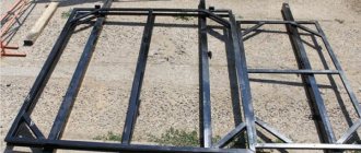
Sanding beds
See prices for grinding beds >>
PHOENIX LLC carries out grinding of guide frames on a Waldrich Coburg machine
We carry out grinding of beds of various types of machines. For example:
- guides for lathe beds with RMC up to 6 meters (1M63, 1M65, 16K20, 16M30, 1A983, etc.);
- guides for milling machine beds (6T13, 6K81, 6T83, etc.);
- guides for grinding machine beds (3L722, 3B724, etc.);
- carriage groups, consoles, racks, tables.
The average production time for 1 set is 5 working days.
Find out the cost of grinding (grinding price)
Just check out our sanding price list. Our prices for grinding will pleasantly surprise you! Prices for grinding beds, carriage groups, racks, etc.
Maximum parameters of processed products:
| Maximum grinding length, mm | 8590 |
| Table width, mm | 1800 |
| Passage between racks, mm | 2020 |
| Grinding height, mm | 1580 |
| Maximum weight of the processed product, kg | 12500 |
Information on prices and lead times for orders for grinding guides can be found by calling:
Quality control when grinding beds
We carefully monitor the quality of all services we provide. Sanding the beds was no exception.
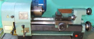
Lathe device
A classic lathe made in the USSR consists of the parts shown in the drawing:
Lathe device - front view
This figure does not show everything, only some parts, but this is enough for a basic understanding. The parts that are related to electrical are highlighted.
- 8 – handle for clutch and switching direction of spindle rotation. The important thing is that this handle acts on the zero stroke limit switch - while it is pressed, the machine will not turn on.
- 12 – Start and Stop buttons for controlling the main engine.
- 21 – non-latching button to turn on the high-speed motor (accelerated movement of the carriage).
- 24 – lighting lamp.
- 27 – direct connection ammeter, for monitoring the main motor current.
- 28 – toggle switch for turning on the engine of the coolant pump (coolant).
- 29 – power on indicator.
- 30 – power handle.
Daily care
The most reliable care for a lathe is to prevent damage to it. Preparation for the next work shift should be carried out immediately after finishing work and disconnecting the machine from the power supply. At this stage of maintenance, the following operations are performed:
- Chips and other technical debris are swept away from the surface.
- It is necessary to dissolve oil and dirt with kerosene and wipe dry with a rag.
- To avoid corrosion, all parts that do not have a paint coating are lubricated with oil.
- The oil cans are filled with grease.
Before starting a shift, it is necessary to check the presence of lubricant and inspect the equipment for damage or loose parts. During work, it is necessary to observe safety precautions when working with turning mechanisms - this will minimize injuries in the workplace and reduce the risk of equipment breakdown. During work you must:
- The use of protective screens, which will avoid clogging the lathe with metal shavings and small abrasive particles that arise during processing of the part.
- Timely replacement of drilling and cutting parts.
- Control over the reliability of fastenings of cutters and drills.
- During operation, do not allow the formation of long chips, which, if wound around the rotating parts, can damage the mechanism.
- You can turn on the machine only after the cutter is lowered onto the blank, in the place specified in the drawing.
Video covering basic maintenance principles.
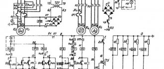
Electrical circuit of a lathe
I decided to give a diagram of a 16K20 lathe and similar ones that I encounter most often. When describing the circuit, I will give photos and principles of operation of each element.
Typical diagram of a lathe
General view of the electrical cabinet:
Lathe control cabinet - door open
First, let's look at the power part (according to the diagram - to the left of the transformer).
Automatic opening and door locking system
The input machine F1 is a power switch; it is activated by a handle located on the front panel:
Control panel of a lathe before repair. Power switch, power indicator, cooling system switch, ammeter.
Introductory automatic machine. There are no wires on the upper terminals
The input terminals, as can be seen in the photo, are often burnt because factory electricians approach this important place carelessly. And machines are often moved to another location and reconnected.
The grounding system is always TN-C, that is, the combined PEN conductor is screwed to the housing and to the neutral. More precisely, neutral N and ground are screwed onto one chassis bolt.
The H1 – S1 – F1 system is used to ensure that when the door is opened, the F1 machine is switched off and the machine is completely de-energized. If an electrician has a lot of experience and a special key, he can bypass this system.
Security system - indicator H1, door opening limit S1, switch PU, automatic F1. The back of the ammeter is also visible.
To do this, after opening the door, you need to insert and turn the key at the control panel, and turn on the machine again. At the same time, the H1 lights will flash.
But usually (always) the security key is lost, the PU switch is broken with a screwdriver, and brave electricians (and sometimes turners!) climb into the machine under voltage. I'm telling it like it is.
Main contactor
Contactor K1 is the most powerful in the machine. It includes, in addition to the M1 engine (spindle, power 7.5 or 10 kW), a hydraulic station engine. However, hydraulic support is extremely rarely available, so we will not consider the M4 engine and the F7 thermal relay.
Spindle motor main contactor
In addition to the contactor, there is also a thermal relay F5, pictured below. The old type thermal relay has two poles (controls two phases). One of the phases goes through an ammeter. Three blue wires go to the M1 motor.
The main engine transmits rotation to the gearbox via a belt drive.
Fast movement of the carriage and coolant
Through the F2 circuit breaker (about 6 A), power is supplied through the K4 contactor to the M2 high speed motor. It is manually turned on for a short time and therefore has no thermal protection. Through the same automatic machine and contactor K2, the M3 engine is powered; it rotates the coolant supply pump. The pump is turned on manually using a toggle switch on the control panel.
Lighting
Something as simple as a lamp is always broken. It has to be replaced or repaired. It is important that there is a 24 or 36 V lamp there, and for safety reasons it is necessarily powered through a transformer.
In the diagram - F3, S9, H2. Such lamps are available for sale, they are called “machine lamps”.
Transformer
Let's move on to the control part. It is powered by a voltage of 110 V from a transformer.
Machine transformer - necessary for safe and correct operation of the control part
This is an isolated neutral system (that is, this part of the circuit operates without grounding) - perhaps the safest one available.
Some electricians, in order to save money or out of ignorance, throw away the transformer. It is very dangerous! Then all parts of the circuit will be under dangerous voltage!
Control buttons
We are talking about buttons S3, S4 (Stop, Start).
Control buttons Start, stop to control the start of the main engine
The diagram shows that this is a classic self-retaining scheme. But in a lathe it has its own characteristics.
The control circuit is powered through fuse F4 (I usually set the machine to 2 or 4 A) and the Stop button.
When you press the Start button, the engine will only start if several conditions are met. Namely, contacts S6 – S5 – F7 – K3 – F5 are closed. Only then will power be supplied to the coil of contactor K1, and it will power itself with its contacts.
The buttons can be replaced with new ones, PKE type, but it is better to clean and repair those made in the USSR than to install new ones.
Zero stroke limit
As I wrote above, the zero stroke limit S6 must be in the neutral (not pressed) position in order for the engine to start.
End protection against false switching
Drive end cover
If limit switch S5 is not pressed (belt drive cover is not closed), the engine will not turn on. This is again a safety requirement.
Belt drive end protection, installation location shown by arrow
The photo shows the installation location, but the end itself is not there. It is often not installed, or is forced to close so that the cover can be removed during operation. This is a security breach!
Thermal protection
Next along the start circuit are thermal relay contacts F5 and F7. It’s clear here - when overloaded, the relay contacts open, and the engine will not start until the problem is resolved, then you need to manually turn on the relay.
Coolant pump contactor and thermal relay
Read my articles on choosing a thermal relay and contactor.
Time relay – no-load protection
Time relay K3 type RVP-22 is turned on when the Start button S4 is pressed. Further, if the zero stroke limit S6 does not open (the spindle does not start to rotate), the contacts of the time relay K3 with a switch-on delay will open, the contactor K1 will turn off, and the main motor will stop.
Time relay for idle protection
What is this system for? The fact is that when the gearbox rotates at idle, some parts in it may overheat (what exactly is a question for the mechanics). Therefore, if the turner does not select the direction of rotation, the engine will stop.
At any time, if the spindle stops while the motor is rotating, the timing begins, about 30-60 s.
I have a large review article on time relays.
Unfortunately, if the time relay fails, its contacts do not allow the engine to start. As a result, in the absence of spare parts, they are short-circuited and “out of position.” I install electronic time relays instead of outdated models.
Wedge restoration
If the wedges are worn out a lot, repair usually comes down to their complete replacement, which is associated with additional costs of metal and time spent on making new wedges.
Repair experience using new technology shows that all wedges, regardless of their wear, can be restored. The new repair technology is based on the use of styracrylic and appropriate preparation of wedges for pouring.
Experience shows that the labor intensity of repairing wedges using the proposed technology is reduced by approximately 35%, while manual scraping work associated with adjusting the wedges in place is almost completely eliminated.
The technological process for restoring wedges with styracrylic (Fig. 72) is presented in table. 12.
Schedule and composition of repair and maintenance work
When the machine operates under normal operating conditions and compliance with all operating and maintenance rules specified in this manual, the overhaul cycle (service life before major repairs during two-shift operation) is (mainly) at least 9 years when processing steel (mainly), and at least 8 years for cast iron years. Maintenance and repair work is recommended to be carried out according to the repair work schedule (Fig. 39).
Machine inspection
- External inspection of the machine (without disassembling to identify defects) of the condition and operation of the machine as a whole and by components;
- Inspection and check of the condition of the main movement and feed drive mechanisms;
- Adjusting the table lead screw clearances;
- Spindle bearing adjustment;
- Checking the operation of speed and feed switching mechanisms;
- Regulation of the mechanisms for switching on cam clutches and feeds and the high-speed friction clutch;
- Adjustment of table wedges, slides, console and trunk;
- Inspection of guides, cleaning of nicks and burrs;
- Tightening loose fasteners;
- Checking the operation of the limiting cams;
- Checking the condition and minor repairs of cooling and lubrication systems;
- Checking the condition and repairing protective devices;
- Identification of parts that require replacement during the next repair (starting with the second minor repair);
Small machine repair
- Partial disassembly of components;
- Flushing all components;
- Adjustment or replacement of rolling bearings;
- Cleaning burrs and nicks on gear teeth, crackers and shift forks;
- Replacement and addition of friction discs of the high-speed clutch (starting from the second repair);
- Scraping and cleaning of wedges and strips;
- Cleaning the lead screws and replacing worn nuts;
- Cleaning nicks and burrs on the guides and working surface of the table;
- Replacing worn and broken fasteners
- Checking and adjusting the mechanisms for switching on speeds and feeds;
- Repair of lubrication and cooling systems;
- Testing the machine at idle speed, checking for noise, heating and accuracy of the workpiece.
Rear box
The rear junction box is often broken or in poor condition.
Rear box with terminal block
All the wires that go through the terminal block of this box have to be re-tightened (new ones installed), since the oil makes them brittle. Through this box there are wires to the Start and Stop buttons and to the high speed button, as well as power to the lamp.
Can compressed air be used when cleaning a CNC machine?
During daily maintenance of a CNC machine, it is important not only to perform the work efficiently, but also to apply as little effort as possible and spend as little precious working time as possible. Using a compressed air gun frees hard-to-reach areas of the CNC machine structure from dust and chips much faster, which allows cleaning to be done several times faster
However, manufacturers of CNC machines strongly discourage the use of compressed air during maintenance and cleaning, and there are several reasons for this:
- Dust and dirt, including that generated during the processing of MDF and lifted from the concrete floor, have good abrasive properties. By getting under high pressure jets of compressed air even into closed bearings of electric spindles, ball screws, linear guides and other mechanisms, abrasive dust significantly reduces their service life.
- Dust flying in a stream of compressed air can penetrate the electronic components of a CNC machine and settle on electrical contacts. After some time, the density of the layer of dust deposited on the contacts can reach a level at which the electronic device fails.
- Compressed air may contain drops of water, which, if they get on exposed metal parts of the machine, can cause corrosion, when interacting with the contacts of electrical switches and relay devices, they can cause oxidation, and if they penetrate inside complex electronic devices, they can cause a short circuit.
- The efficiency of dust collection with compressed air tends to zero, since lightweight fractions rise and hang in the air, and after some time settle on the surfaces of the CNC machine, on the floor, on workpieces, thereby making cleaning not only useless, but also inappropriate.
- Dust particles from wood chips and concrete floors raised into the air, entering a person’s lungs, are harmful to his health.
As a rule, when performing operations and maintenance of a CNC machine in the production of furniture and MDF facades, compressed air is used as the fastest and most effective way to clean work tables from chips and dust. To clean the remaining parts of the CNC machine using compressed air, you should follow some recommendations:
- You can only blow air on the milling spindle when the CNC machine is turned on. The fact is that modern spindles are connected to a compressed air system, which creates a high-pressure area inside them, thereby preventing dust from entering the bearings. Directing a jet of compressed air into the electrospindle shaft is prohibited.
- A chuck (mandrel) with any tool must first be installed in the quick tool change mechanism of the milling spindle.
- Near the location of bearings and electrical devices, a compressed air gun should be used at a maximum distance, sufficient only to blow off small loose fractions.
- It is prohibited to direct a jet of compressed air at the impellers of the spindle cooling systems or the electrical cabinet of the CNC machine.
- Before using a compressed air gun, you still need to use a vacuum cleaner, brush or cloth.
Thus, if these recommendations are followed, daily maintenance of the CNC machine will indeed be useful, including to ensure uninterrupted operation of the equipment and extend its service life.
Fast movement of carriage and caliper
To manually move the carriage lengthwise and crosswise, use the M2 motor, activated by the K4 contactor. The contactor is turned on by a button (limit without locking), which is built into the carriage movement handle.
Below is a photo of a similar 1K62 lathe, which shows a support, a carriage, and an arrow indicating the button for turning on the fast travel motor.
Caliper quick movement button
The rapid movement motor is located on the right side of the frame, rotation is transmitted through a belt.
Installing the Lead Screw and Lead Shaft
This operation is excluded if the carriage repair is performed according to table. 5.
The alignment of the axes of the lead screw and the lead shaft, the feed box and the apron is carried out in accordance with the following standard technological process.
1. Install the feed box housing and secure it to the frame with screws and pins.
2. Install the carriage in the middle part of the frame and attach the rear clamping bar of the carriage with screws.
3. Install the apron and connect it to the carriage with screws (the apron may not be installed fully assembled).
4. in the holes of the feed box and apron for the lead screw or lead shaft. The ends of the mandrel must protrude by 100-200 mm and have the same diameter of the protruding part with a deviation of no more than 0.01 mm (play of the mandrels in the holes is unacceptable).
5. Move the carriage with the apron to the feed box until the ends of the mandrels touch and measure the amount of their misalignment (in the light) using a ruler and a feeler gauge.
6. Restore the alignment of the holes for the lead screw and the lead shaft in the feed box and apron by installing new linings, scraping the guides or carriage linings, and reinstalling the feed box.
Permissible deviation from the alignment of the feed box and apron holes: in the vertical plane - no more than 0.15 mm (the axis of the apron hole can only be higher than the feed box hole), in the horizontal plane - no more than 0.07 mm.
Reinstallation of the box height should be done when repairing carriage guides without compensating pads. In this case, the holes in the feed box for the screws securing it to the frame are milled. When moving the box horizontally, it is necessary to mill holes in the carriage for the apron fastening screws: the latter must also be shifted and then pinned again.
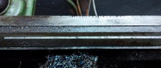
Scraping lathe guides
Restoring the geometry of lathe guides
Grinding the bed guides of a screw-cutting lathe
Grinding the bed guides of a screw-cutting lathe
Restoring a lathe bed
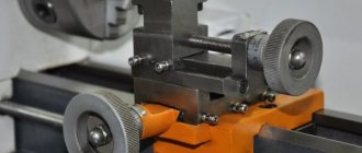
Typical control unit
When considering a modern universal screw-cutting lathe, you should pay attention to the control unit. To indicate the main processing parameters, levers and handles, buttons and other control units are installed
The main features include the following points:
- As a rule, a handle is installed to indicate the number of revolutions. A universal modern screw-cutting lathe can change this indicator, which is selected depending on the required cutting conditions.
- A screw-cutting lathe has a device that allows the formation of a threaded surface. Its parameters are set using a special control unit. Do not forget that some parameters can be set solely by installing the required replacement wheels.
- There are also handles that allow you to control the caliper. Screw-cutting lathes have main components that allow mechanical feed for quick positioning and processing with a constant movement speed.
Controls of screw-cutting lathes using the example of model 16K20
The CNC screw-cutting lathe has a more complex layout. This is due to the fact that such equipment can operate without operator intervention at intermediate stages.