I decided to build my first pulse metal detector, Clone PI-W, and now it comes to making a mono search coil. And since I am currently experiencing some financial difficulties, I was faced with the difficult task of making a reel myself from the cheapest materials possible.
Looking ahead, I’ll say right away that I coped with the task. As a result, I got this sensor:
By the way, the resulting ring coil is perfect not only for Clone, but also for almost any other impulse generator (Koschei, Tracker, Pirate).
Next, I will tell you how to make a search coil for a metal detector with your own hands, spending less than 500 rubles on it.
I will tell you in great detail, since the devil is often in the details. Moreover, there are a dime a dozen short stories about making reels on the Internet (like, take this, then cut it off, wrap it, glue it and you’re done!) But you start doing it yourself and it turns out that the most important things were mentioned in passing, and some things were completely forgotten to say ... And it turns out that everything is more complicated than it seemed at the very beginning.
This won't happen here. Ready? Go!
Idea
The easiest design for me to make on my own seemed to be this: take a disk made of sheet material ~4-6 mm thick. The diameter of this disk is determined by the diameter of the future winding (in my case it should be 21 cm).
Then we glue two disks of slightly larger diameter to this pancake on both sides to make a bobbin for winding wire. Those. such a coil greatly increased in diameter, but flattened in height.
For clarity, I’ll try to depict this in a drawing:
I hope the main idea is clear. Just three disks glued together over the entire area.
Material selection
I planned to use plexiglass as the material. It is perfectly processed and glued with dichloroethane. But, unfortunately, I couldn’t find it for free.
All sorts of collective farm materials such as plywood, cardboard, bucket lids, etc. I immediately discarded them as unsuitable. I wanted something strong, durable and preferably waterproof.
And then my gaze turned to fiberglass...
It's no secret that fiberglass (or glass mat, fiberglass) is used to make whatever your heart desires. Even motor boats and car bumpers. The fabric is impregnated with epoxy resin, given the desired shape and left until completely cured. The result is a durable, water-resistant, easy-to-handle material. And this is exactly what we need.
So, we need to make three pancakes and ears for attaching the barbell.
Manufacturing of individual parts
Pancakes No. 1 and No. 2
Calculations have shown that to obtain a sheet 5.5 mm thick, you need to take 18 layers of fiberglass. To reduce epoxy consumption, it is better to cut the fiberglass fabric in advance into circles of the required diameter.
For a disk with a diameter of 21 cm, 100 ml of epoxy resin was just enough.
Each layer must be thoroughly coated, and then the entire stack must be placed under the press. The greater the pressure, the better - the excess resin will be squeezed out, the mass of the final product will become a little less, and the strength will be a little greater. I loaded about a hundred kilograms on top and left it until the morning. The next day I ended up with this pancake:
This is the most massive part of the future coil. He weighs - be healthy!
Then I’ll tell you how using this spare part it will be possible to significantly reduce the weight of the finished sensor.
A disk with a diameter of 23 cm and a thickness of 1.5 mm was made in exactly the same way. Its weight is 89 g.
Pancake #3
There was no need to glue the third disk. I had at my disposal a sheet of fiberglass of suitable size and thickness. It was a printed circuit board from some ancient device:
Unfortunately, the board had metallized holes, so I had to spend some time drilling them.
I decided that this would be the top disk, so I made a hole in it for the cable entry.
Ears for barbell
There was just enough leftover textolite for the ears to attach the sensor housing to the rod. I cut out two pieces for each ear (to make it durable!)
You should immediately drill holes in your ears for the plastic bolt, as it will be very inconvenient to do this later.
By the way, this is a mounting bolt for the toilet seat.
So, all the components of our coil are ready. All that remains is to glue it all together into one big sandwich. And don't forget to run the cable inside.
Coil for pulse metal detector made of twisted pair
From a twisted pair of wires it is possible to build a wonderful sensor, which is an indispensable component for a pulse device. Such a coil will have a search depth of more than one and a half meters. This design is distinguished by good sensitivity to various small-sized products, which include gold jewelry, small change, etc. In order to make such a coil, you need to first prepare a twisted pair wire, which can be purchased without any problems wherever radio devices are sold. The wire is made of four twisted pairs without a screen, it is very important that it be copper and not bimetallic
In order to make such a coil, you need to follow these instructions:
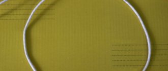
· Make a piece of wire, the length of which is 2.7 meters. · Mark exactly half of the section. After this, you should also measure 41 cm from each end. · According to the marks made, you need to make a ring from this wire and fix it using ordinary tape or adhesive tape. · The ends of the future coil should be slightly bent inward.
· Next comes a thorough stripping of the wire insulation, after which you will need to solder these wires in this order:
Assembly into one piece
First, the upper disk made of holey fiberglass was glued to the middle pancake made of 18 layers of fiberglass. This took literally a few milliliters of epoxy - this was enough to coat both surfaces to be glued over the entire area.
Ear mounting
I cut the grooves using a jigsaw. Naturally, I overdid it a little in one place:
To make the ears fit well, I made a small bevel on the edges of the cuts:
Now we had to decide which option is better? Ears can be placed in different ways...
Industrially produced reels are often made according to the right-hand version, but I prefer the left-handed one. In general, I often make leftist decisions...
In theory, the right method is better balanced, because The rod mount is closer to the center of gravity. But it is far from a fact that after lightening the coil, its center of gravity will not shift in one direction or another.
The left mounting method looks more visually pleasing (IMHO), and in this case the total length of the metal detector when folded will be a couple of centimeters shorter. For someone who plans to carry the device in a backpack, this may be important.
In general, I made my choice and started gluing. He generously smeared it with bauxite, securely fixed it in the desired position and left it to harden:
After hardening, I sanded off everything sticking out from the back side with sandpaper:
Cable entry
Then, using a round file, I prepared grooves for the conductors, inserted the connecting cable through the hole and glued it tightly:
To prevent strong kinks, the cable at the entry point needed to be somehow reinforced. For these purposes, I used this little rubber thing that I got from God knows where:
Of course, if I had a normal sealed lead-in, it would be much better, but... it will do.
All that remained was to glue the third pancake (the bottom).
Finishing the frame
To glue the third pancake it took several milliliters of bauxite and a couple of hours for everything to set. Here's the result:
Thus, I received a rigid and durable frame, fully prepared for winding the wire.
Winding sealing
An enameled copper wire with a diameter of 0.71 mm was used as a winding wire. After winding 27 turns, the sensor became heavier by another 65 grams:
Now the winding had to be caulked somehow. As putty I used a mixture of epoxy resin and finely chopped fiberglass (I learned about this super recipe from this article).
In short, I cut some fiberglass:
and mixed it thoroughly with bauxite with the addition of ballpoint pen paste. The result was a viscous substance similar to wet hair. With this composition you can cover any cracks without problems:
Pieces of fiberglass give the putty the necessary viscosity, and after hardening, provide increased strength to the adhesive joint.
So that the mixture is properly compacted, and the resin saturates the turns of the wire, I wrap it all with electrical tape tightly:
The electrical tape must be green or, at worst, blue.
After everything froze thoroughly, I wondered how strong the structure turned out to be. It turned out that the reel could easily support my weight (about 80 kg).
In fact, we don’t need such a heavy-duty reel; its weight is much more important. Too much mass of the sensor will definitely cause shoulder pain, especially if you plan to conduct a long search.
TEMPLATE FOR METAL DETECTOR SENSORS HOUSINGS
Much has already been said and written about vacuum molding of housings for metal detector sensors. It seems to be nothing complicated. A vacuum cleaner, an oven and a box made from improvised materials with many holes. The main question is where to get the template for the body. And so, when I felt the urge to make another sensor, I decided to write this article. So, let's begin. First of all, you need to make a drawing of the sensor in any graphics editor, I use Visio from Microsoft.When the drawing is ready, we print it out and move to the manufacturing site. I make templates from 20 mm plywood. For my work, a small circular saw, a jigsaw and a drill are very useful to me.
First, glue the drawing onto the plywood and trim off all excess from the outside. Then, holes with the required radius must be drilled in all internal corners. Particular attention must be paid to the perpendicularity of the holes. Otherwise, difficulties may arise when extracting the template.
Next, using a jigsaw, we cut out all the excess from the inside.
Now that we already have a silhouette dear to our hearts in our hands,
We arm ourselves with sandpaper, all kinds of files and rasps, and patiently level out all the unevenness.
If possible, it is necessary to make a slight narrowing at the top, again to make it easier to remove the template from the finished product. Then, in the place where the pressure seal is attached, it is advisable to glue a boss. It will allow you to hide the sealed lead-in nut, and the latter will not interfere with the placement of the capacitors.
Next, using a circular saw, we make the ears. The distance between them was 24 mm, taking into account the thickness of the plastic.
Glue the ears to the template.
To better retract the plastic, it is advisable to make small through holes in the corners.
Voila! Our template is ready.
It took me less than three hours to make, not counting the preparation of the drawing. It remains to check it in action.
And here is the result.
I mostly use white plastic for sensors. It heats up less in the sun, and accordingly the balance floats less. But that is another story. I wish you success. I hope that the article is useful to someone. Attached is a drawing of a butterfly in MSVisio and PDF. Best regards, Slavochny .
Metal detector forum
Forum for discussing the material TEMPLATE FOR CASES OF METAL DETECTOR SENSORS WIRELESS
POWER POWER POSSIBILITIES
About the use of wireless power technology for various devices.
MEMS microphones are a new quality in sound recording. Detailed description of the technology.
Homemade functional signal generator 0.1 Hz - 100 kHz on the ICL8038 chip.ELECTROMAGNETIC GAUSS RIFLE
Review of several more schemes and ready-made Gauss Gun designs from Aliexpress.
Facilitating
To reduce the weight of the coil, it was decided to cut out some sections of the structure:
This manipulation allowed me to lose 168 grams of excess weight. At the same time, the strength of the sensor has practically not decreased, as can be seen in this video:
Now, with hindsight, I understand how the coil could have been made a little lighter. To do this, it was necessary to make large holes in the middle pancake in advance (before gluing everything together). Something like this:
The voids inside the structure would have almost no effect on the strength, but would reduce the total mass by another 20-30 grams. Now, of course, it’s too late to rush around, but I’ll keep it in mind for the future.
Another way to simplify the design of the sensor is to reduce the width of the outer ring (where the wire turns are laid) by 6-7 millimeters. Of course, this can be done now, but there is no such need yet.
Spontaneous signals
But there is another factor that can both darken the search and completely discourage the desire to engage in this hobby in general - this is an incorrectly wound coil cable. Here's the thing. On the one hand, and I already talked about this, if the cable is wound incorrectly, there is every chance that with an unsuccessful swing, when the coil cable catches a little on the grass, the wire will simply fly out of the socket.
Another option is possible, when a search engine identifies a find in a dump, puts its own next to it, and for convenience bends the reel. Moreover, if the cable is wound incorrectly, separation is inevitable. On the other hand, I have had cases when I already thought that my metal detector had gone crazy, since the spontaneous signals were tormented. As it turned out later, the whole point was that the cable was wound incorrectly.
Finish painting
I found an excellent paint for fiberglass and fiberglass products - epoxy resin with the addition of a dye of the desired color. Since the entire structure of my sensor is made on the basis of bauxite, the resin-based paint will have excellent adhesion and will fit like original.
I used alkyd enamel PF-115 as a black dye, adding it until the required hiding power was obtained.
As practice has shown, a layer of such paint holds very firmly, and looks as if the product was dipped in liquid plastic:
In this case, the color can be any depending on the enamel used.
The final weight of the search coil together with the cable after painting is 407 g
The cable separately weighs ~80 grams.
Cable fixation
A lot has been written about how to properly wind a cable, and some manufacturers even make videos on this topic so that users can see with their own eyes how and what to do. But, for some reason, attention is often paid only to the lower section of the cable, which is located directly next to the coil itself; I must admit, I myself had not thought much about this topic before.
But, as it turned out in my case, additional fixation of the cable in two more places allows me to avoid some spontaneous signals. Perhaps the whole point is that in the area where the cable enters the metal detector block, if the fixation is weak, some minimal movements may occur, which leads to a false signal. In general, I do this:
1. I fix the cable to the reel as recommended by the search community (so that the free movement of the reel is maintained and the cable is not strained). 2. I make the second turn of electrical tape approximately in the middle of the assembled rod, and additionally secure the cable. 3. The third fixation area is located approximately 10-15 cm from the metal detector block.
The time it takes to carry out these manipulations is minimal, and the result makes me happy. At the same time, do not forget that the plug from the coil that you insert into the metal detector unit must be dry, since moisture getting on the contacts will not have the best effect on the operation of the detector. Well, the fixing nut itself needs to be tightened so that the cable does not dangle, otherwise false signals cannot be avoided.
This is a simple observation that, in my opinion, made my search more effective.
PS For some time, I used special Velcro to secure the cable to the rod, which, by the way, I already wrote about.
But in the end, I returned to duct tape again, since this material is more convenient for me, and if something happens, duct tape can be bought at literally any stall, be it a city or a village. Your Alexander Maksimchuk!
The best reward for me as an author is your like on social networks (tell your friends about this article), also subscribe to my new articles (just enter your email address in the form below and you will be the first to read them)! Don’t forget to comment on the materials, and also ask any questions you have about treasure hunting! I am always open to communication and try to answer all your questions, requests and comments! Feedback on our website works stably - don’t be shy! When manufacturing metal detectors of any type, special attention should be paid to the quality of the search coil (coils) and its precise tuning to the operating search frequency. The detection range and stability of the generation frequency greatly depend on this. It often happens that with a correct and fully operational circuit, the frequency “floats”, which can, of course, be explained by the temperature instability of the elements used (mainly capacitors). I have personally assembled more than a dozen different metal detectors, and in practice, the temperature stability of passive elements still does not provide guaranteed frequency stability if the search coil itself is made carelessly and its precise tuning to the operating frequency is not ensured. Next, practical recommendations will be given on the manufacture of high-quality sensor coils and their configuration for single-coil metal detectors.
Making a good reel
Typically, metal detector coils are wound “in bulk” on some kind of mandrel - a pan, a jar, etc. suitable diameter. Then they wrap it with electrical tape, shielding foil and again with electrical tape. Such coils do not have the necessary structural rigidity and stability, are very sensitive to the slightest deformation and greatly change the frequency even with simple squeezing with your fingers! A metal detector with such a coil will have to be adjusted every now and then, and the control knob will constantly leave your fingers with big sore calluses :). It is often recommended to “fill such a coil with epoxy,” but where should one fill it, epoxy, if the coil is frameless?.. I can offer a simple and easy way to make a high-quality coil, sealed and resistant to all kinds of external influences, with sufficient structural rigidity and, moreover, the same, providing simple attachment to a stick-bar without any brackets.
For the frame, coils can be made using a plastic box (cable channel) of a suitable cross-section. For example, for 80 - 100 turns of wire with a cross-section of 0.3...0.5 mm, a box with a cross-section of 15 X 10 or less is quite suitable, depending on the cross-section of your specific wire for winding. Single-core copper wire for low-current electrical circuits is suitable as a winding wire; it is sold in coils, such as CQR, KSPV, etc. This is bare copper wire with PVC insulation. The cable may contain 2 or more single-core wires with a cross-section of 0.3 ... 0.5 mm in insulation of different colors. We remove the outer sheath of the cable and get several necessary wires. Such a wire is convenient in that it eliminates the possibility of short-circuiting turns due to poor-quality insulation (as in the case of wires with varnish insulation of PEL or PEV brands, where minor damage is not visible to the eye). To determine how long the wire should be to wind the coil, you need to multiply the circumference of the coil by the number of its turns and leave a small margin for the terminals. If you do not have a piece of wire of the required length, you can wind it from several pieces of wire, the ends of which are well soldered to each other and carefully insulated with electrical tape or using heat-shrink tubing.
Remove the cover from the cable channel and cut the side walls with a sharp knife every 1 ... 2 cm:
After this, the cable channel can easily go around a cylindrical surface of the required diameter (jar, pan, etc.), corresponding to the diameter of the metal detector coil. The ends of the cable channel are glued together and a cylindrical frame with sides is obtained. It is not difficult to wind the required number of turns of wire onto such a frame and coat them, for example, with varnish, epoxy, or fill everything with sealant.
From above, the frame with the wire is closed with a cable channel cover. If the sides of this lid are not high (this depends on the size and type of box), then you don’t have to make side cuts on it, because it bends quite well anyway. The output ends of the coil are brought out next to each other.
This results in a sealed coil with good structural rigidity. All sharp edges, protrusions and irregularities in the cable channel should be smoothed using sandpaper or wrapped with a layer of electrical tape.
After checking the coil for functionality (this can be done by connecting the coil even without a screen to your metal detector for the presence of generation), filling it with glue or sealant and mechanically processing the irregularities, you should make a screen. To do this, take foil from electrolytic capacitors or food foil from the store, which is cut into strips 1.5 ... 2 cm wide. The foil is wound tightly around the coil, without gaps, overlapping. Between the ends of the foil at the coil terminals you need to leave a gap of 1 ... 1.5 cm
, otherwise a short-circuited turn will form and the coil will not work. The ends of the foil should be secured with glue. Then the top of the foil is wrapped along the entire length with any tinned wire (without insulation) in a spiral, in increments of about 1 cm. The wire must be tinned, otherwise incompatible metal contact (aluminum-copper) may occur. One end of this wire will be the coil's common wire (GND).
Then the entire coil is wrapped with two or three layers of electrical tape to protect the foil screen from mechanical damage.
Tuning the coil to the desired frequency involves selecting capacitors, which together with the coil form an oscillatory circuit:
The actual inductance of the coil, as a rule, does not correspond to its calculated value, so the desired circuit frequency can be achieved by selecting appropriate capacitors. To facilitate the selection of these capacitors, it is convenient to make a so-called “capacitor store”. To do this, you can take a suitable switch, for example, the P2K type with 5 ... 10 buttons (or several such switches with fewer buttons), with dependent or independent latching (all the same, the main thing is that it is possible to turn on several buttons at the same time). The more buttons there are on your switch, the correspondingly more containers can be included in the “store”. The diagram is simple and is shown below. The entire installation is hinged, the capacitors are soldered directly to the button terminals.
Here is an example for selecting capacitors in a series oscillatory circuit
(two capacitors + coil) with capacities of about 5600 pF.
By switching buttons, you can use different capacities indicated on the corresponding button. In addition, by turning on several buttons at the same time, you can get the total capacities. For example, if you press buttons 3 and 4 simultaneously, we get a total capacitance of 5610 pF (5100 + 510), and when you press 3 and 5 – 5950 pF (5100 + 850). In this way, you can create the necessary set of capacitors to accurately select the desired circuit tuning frequency. You need to select capacitor capacities in the “capacitance store” based on the values given in your metal detector circuit. In the example given here, the capacitances of the capacitors according to the diagram are indicated as 5600pF. Therefore, the first thing included in the “store” is, of course, these containers. Well, then take capacitances with lower ratings (4700, 4300, 3900 pF for example), and very small ones (100, 300, 470, 1000 pF) for a more accurate selection. Thus, by simply switching buttons and their combinations, you can obtain a very wide range of capacitances and tune the coil to the required frequency. Well, then all that remains is to select capacitors with a capacitance equal to what you got as a result at the “capacitance store”. Capacitors with such a capacity should be placed in the working circuit. It should be borne in mind that when selecting containers, the “magazine” itself must be connected to the metal detector with exactly the same wire/cable that will be used in the future, and the wires connecting the “magazine” to the coil must be made as short as possible
!
Because all wires also have their own capacity. For a parallel circuit
(one capacitor + coil), it will be enough to use in the “store”, respectively, one capacitor for each rating. After selecting them, it is better to solder the capacitors directly to the coil terminals, for which it is convenient to make a small mounting plate from foil PCB and fix it on a rod next to the coil or on the coil itself:
Discuss the article METAL DETECTORS: ABOUT COILS
The main advantage that pulse devices have for searching for objects made of non-ferrous metal is that it is quite simple to build a coil for a metal detector from twisted pair. Equipped with a fairly simple coil, these devices have excellent detection performance. This article will describe detailed instructions for creating a twisted pair coil for the Pirate metal detector, thanks to which you can make this design yourself. Thanks to this, you will not need to purchase it on the radio market for a rather impressive amount. In the process of work, you will need standard elements that every electronics engineer probably has in stock. Coils, which are created by the simple methods below, can be used with almost all impulse devices that are very popular today.
Examination
After our homemade metal detector coil was completely ready, we had to check it for internal breaks. The easiest way to check is to use a tester to measure the winding resistance, which normally should be very low (maximum 2.5 Ohms).
In my case, the resistance of the coil together with two meters of connecting cable turned out to be around 0.9 Ohm.
Unfortunately, this simple method will not be able to detect an interturn short circuit, so you have to rely on your accuracy when winding. A short circuit, if there is one, will immediately manifest itself after starting the circuit - the metal detector will consume increased current and have extremely low sensitivity.