History of invention
In 1873, the English scientist Frederick Guthrie developed the operating principle of directly heated vacuum tube diodes.
A year later, in Germany, physicist Karl Ferdinand Braun suggested similar properties in solid-state materials and invented a point rectifier. In early 1904, John Fleming created the first complete tube diode. He used copper oxide as the material for its manufacture. Diodes have begun to be widely used in radio frequency detectors. The study of semiconductors led to the invention of the crystal detector in 1906 by Greenleaf Witter Pickard.
In the mid-30s of the 20th century, the main research of physicists was aimed at studying the phenomena occurring at the metal-semiconductor contact boundary. Their result was the production of a silicon ingot with two types of conductivity. While studying it, in 1939, the American scientist Russell Ohl discovered a phenomenon later called the pn transition. He found that depending on the impurities existing at the interface of two semiconductors, the reducibility changes. In the early 50s, Bell Telephone Labs engineers developed planar diodes, and five years later, germanium-based diodes with a transition of less than 3 cm appeared in the USSR.
The inventor of the rectifier bridge circuit is considered to be an electrical engineer from Poland, Karol Pollak. Later, the results of Leo Graetz’s research were published in the journal Elektronische Zeitung, so in the literature one can also find another name for a diode bridge - circuit or Graetz bridge.
Smoothing
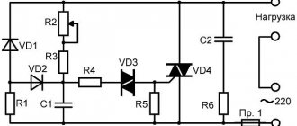
A single-phase electrical full-wave rectifier, no matter how many diodes it combines, requires additional smoothing of the output voltage. Ripple greatly affects the operation of the device itself for which such a rectifier is assembled. To smooth out current ripple, the rectification circuit is supplemented with filters. They can be collected from:
- High-capacity capacitor. Such a filter is a capacitive or “C-filter”. At the moment the diode opens, the capacitor is filled with current and plays the role of capacitance. At the moment the diode closes, the capacitance is gradually discharged, thereby smoothing out the voltage without any surges.
- Inductors. An inductor as a filter can be used in addition to or instead of a capacitor. This filter operates on the principle that there is no instantaneous change in the current across the coil. As a positive half-wave passes through the coil, the current value increases smoothly and slowly. When the half-wave changes to a negative value, the current in the coil changes with a delay, which significantly reduces the sharpness of the pulsation.
When designing diode rectifiers, the load of subsequent circuit elements is taken into account. So, if the resistance after the rectifier is significantly low, then using a capacitive filter is not advisable. At low loads, a larger capacitor will be required. Thus, for such circuits with low resistance, it is more rational to use an inductive filter.
What are diodes
A diode is a semiconductor element based on a silicon crystal. Previously, these parts were also made of germanium, but over time this material was forced out due to its shortcomings. The electrical diode functions as a valve, i.e. it allows current to flow in one direction and blocks it in the other. Such capabilities are built into this part at the level of the atomic structure of its semiconductor crystals.
One diode cannot obtain a full constant voltage from an alternating voltage. Therefore, in practice, more complex combinations of these elements are used. An assembly of 4 or 6 parts, combined according to a special circuit, forms a diode bridge. He is already quite capable of coping with full current rectification.
Interesting. Diodes have parasitic sensitivity to temperature and light. Transparent rectifiers in a glass case can be used as light sensors. Germanium diodes (approx. D9B) are suitable as a temperature-sensitive element. Actually, due to the strong dependence of the properties of these elements on temperature, they stopped producing them.
Midpoint diagram
A midpoint full-wave rectifier involves a transformer with two secondary windings having a central terminal. A transformer with one secondary winding can also be used, but it will necessarily have an output from the center of the winding. In addition, the circuit contains 2 diodes. A rectifier with a zero terminal works due to the formation of EMFs of different directions. Both of these EMFs are equal in magnitude to the generated voltage relative to the center or 0 point. When such a transformer operates, the current on both half-windings is shifted in phase by 180 degrees.
The operating principle of this rectifier is as follows:
- The transformer has terminals “w21” and “w22”, which have opposite meanings.
- The anodes of the valves “vd1” and “vd2” are connected to these pins.
- The voltage applied to each diode is in opposite phase (“u21”–“u22” in the diagram).
- During the first half-cycle, current flows through the open diode “vd1”. Only current with a positive potential flows through its anode. During this half-cycle, the diode “vd2” is in a reverse bias state. It is locked and does not allow current from winding “w22” to pass through.
- During the second half cycle, a current with a positive potential is present at the anode “vd2”, thereby opening the diode. The diode passes current through itself from the “w22” winding. The diode “vd1” remains closed.
A full-wave zero-point circuit operates due to the absence of a bias torque. Each half of the secondary winding operates at its own half-cycle, which means the transformer is in a state of constant load.
pros
The zero-output circuit has advantages only over the single-cycle rectifier model. The main advantages of this scheme:
- During operation, current is transferred from both potentials, thereby saving up to 90% of the original energy.
- 2 diodes evenly distribute the load, extending their service life and significantly reducing the load on the entire circuit.
- The full-wave rectifier circuit assumes a smoothed current ripple, without the use of high-voltage, capacitive capacitors.
Despite a number of advantages, single-phase rectifiers with two diodes have their disadvantages, which will be discussed below.
Minuses
To operate such a clutch, you definitely need a special transformer with 2 secondary windings or one separated, with zero output. Such devices greatly increase the costs of producing high-voltage, powerful devices.
Also a big disadvantage is the reverse current load. The circuit must use diodes with a rated voltage of up to 1000 volts and the ability to withstand temperatures up to +80 degrees. If these parameters are not met, then when the diode closes, an increased temperature and resistance will form. Exceeding the parameters will lead to breakdown of the diode itself.
The next disadvantage is the use of the zero tap itself. Connecting to it involves only using part of the available energy, which greatly reduces the potential of such devices.
Definition
A diode bridge is a circuit solution designed to rectify alternating current. Another name is a full-wave rectifier. It is built from semiconductor rectifier diodes or their varieties - Schottky diodes.
The bridge connection circuit assumes the presence of several (for a single-phase circuit - four) semiconductor diodes to which the load is connected.
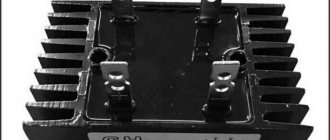
It can consist of discrete elements soldered on a board, but in the 21st century, connected diodes in a separate package are more common. Outwardly, it looks like any other electronic component - legs are removed from a case of a certain standard size for connection to the tracks of the printed circuit board.
It is worth noting that several valves combined in one housing, which are not connected via a bridge circuit, are called diode assemblies.
Depending on the scope of application and connection diagram, diode bridges are:
- single-phase;
- three-phase.
The designation on the diagram can be made in two versions; which UGO to use in the drawing depends on whether the bridge is assembled from individual elements or a ready-made one is used.
Purpose and practical use
The scope of use of a bridge made of diodes is quite wide. These can be power supplies and control units. It is installed in all devices powered by a 220 volt industrial network. For example, TVs, receivers, chargers, dishwashers, LED lamps.
We recommend reading: Frequency converter: design, principle of operation
Cars cannot do without it either. After starting the engine, the generator starts working, producing alternating current. Since the on-board network is all powered by constant voltage, a rectifier bridge is installed through which rectified voltage is supplied. The same constant signal also recharges the battery.
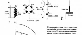
The rectifier device is used to operate the welding machine. True, it uses powerful devices that can withstand currents of more than 200 amperes. The use of diode assembly in devices provides a number of advantages compared to a simple diode. This straightening allows you to:
- increase the ripple frequency, which can then simply be smoothed out using an electrolytic capacitor;
- when working together with a transformer, get rid of the bias current, which makes it possible to more efficiently use the overall power of the converter;
- pass more power with less heat, thereby increasing efficiency.
But it is also worth noting the drawback due to which in some cases the bridge is not used. First of all, this is a double voltage drop, which is especially sensitive in low-voltage circuits. And also, when some of the diodes burn out, the device begins to operate in half-wave mode, which is why parasitic harmonics penetrate into the circuit, which can damage sensitive radioelements.
power unit
Not a single modern power supply can do without a rectifier. High-quality sources are manufactured using bridge rectifiers. The classic scheme consists of only three parts:
- A step-down transformer.
- Rectifier bridge.
- Filter.
A sinusoidal signal with an amplitude of 220 volts is supplied to the primary winding of the transformer. Due to the phenomenon of electromagnetic induction, an electromotive force is induced in its secondary winding and current begins to flow. Depending on the type of transformer, the voltage value is reduced by a certain value due to the transformation ratio.
An alternating signal with reduced amplitude appears between the terminals of the secondary winding. In accordance with the diode bridge connection diagram, this voltage is supplied to its input. Passing through the diode assembly, the alternating signal is converted into a pulsating one.
This form is often considered unacceptable, for example, for sound equipment or lighting sources. Therefore, a capacitor connected in parallel with the output of the rectifier is used for smoothing.
Three-phase rectifier
In production and in places where a three-phase network is used, a three-phase rectifier is used. It consists of six diodes, one pair for each phase. Using this type of device allows you to obtain a higher current value with low ripple. This, in turn, reduces the requirements for the output filter.
The most popular options for connecting three-phase rectifiers are the Mitkevich and Larionov circuits. In this case, not only six diodes can be used simultaneously, but also 12 or even 24. Three-phase bridges are used in diesel locomotives, electric vehicles, on drilling rigs, and in industrial gas and water purification plants.
Thus, the use of bridge rectifiers makes it possible to convert alternating current into direct current, which powers all electronic equipment. Making a diode bridge yourself is not difficult. At the same time, its use allows you to obtain not only a high-quality signal, but also increase the reliability of the device as a whole.
Operating principle
Let's figure out how a diode bridge works. Let's start with the fact that diodes pass current in one direction. AC voltage rectification occurs due to one-way conduction of diodes. Due to their correct connection, the negative half-wave of the alternating voltage is supplied to the load in the form of a positive one. In simple words, it reverses the negative half-wave.
For simplicity and clarity, let's consider its operation using the example of a single-phase full-wave rectifier.
The operating principle of the circuit is based on the fact that diodes conduct current in one direction and is as follows:
- An alternating sinusoidal signal, for example 220V from a household electrical network, is supplied to the input of the diode bridge (in the connection diagram, the input of the diode bridge is designated as AC or ~).
- Each half-wave of sinusoidal voltage (figure below) is passed through a pair of valves located diagonally in the diagram.
The positive half-wave is transmitted by diodes VD1, VD3, and the negative half-wave by VD2 and VD4. You can see the signal at the input and output of the circuit below.
This signal is called rectified pulsating voltage. In order to smooth it out, a filter with a capacitor is added to the circuit.
Electrical parameters
Each type of diode has its own operating and maximum permissible parameters, according to which they are selected for operation in a particular circuit:
- Irev – constant reverse current, µA;
- Upr – constant forward voltage, V;
- Ipr max – maximum permissible forward current, A;
- Urev max – maximum permissible reverse voltage, V;
- Р max – maximum permissible power dissipated by the diode;
- Operating frequency, kHz;
- Operating temperature, C.
Not all diode parameters are given here, but, as a rule, if you need to find a replacement, then these parameters are sufficient.
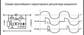
Circuit of a simple AC rectifier using one diode
We will apply AC mains voltage to the input of the rectifier, in which positive half-cycles are highlighted in red and negative half-cycles are highlighted in blue. We will connect a load (Rн) to the output of the rectifier, and a diode (VD) will perform the function of the rectifying element. With positive half-cycles of voltage applied to the anode of the diode, the diode opens.
At these moments of time, a forward diode current Ipr flows through the diode, and therefore through the load (Rн), powered by the rectifier (the half-cycle wave is shown in red in the right graph). With negative half-cycles of voltage supplied to the anode of the diode, the diode closes, and a slight reverse diode current (Irev) will flow throughout the entire circuit. Here, the diode seems to cut off the negative half-wave of the alternating current (in the right graph, such a half-wave is shown by a blue dotted line).
As a result, it turns out that through the load (Rн), connected to the network through a diode (VD), it is no longer alternating current, since this current flows only in positive half-cycles, and the pulsating current is a current of one direction. This is AC rectification. But this voltage can only power a low-power load that is powered by an AC mains and does not have any special power requirements, for example, an incandescent lamp.
Voltage will only pass through the lamp during positive half-waves (pulses), so the lamp will flicker faintly at a frequency of 50 Hz. However, due to thermal inertia, the filament will not have time to cool down in the intervals between pulses, and therefore the flickering will be faintly noticeable. If we power a receiver or power amplifier with this voltage, then in the loudspeaker or speakers we will hear a low-pitched hum with a frequency of 50 Hz, called AC hum. This will happen because the pulsating current, passing through the load, creates a pulsating voltage in it, which is the source of the background.
This drawback can be partially eliminated if a high-capacity filtering electrolytic capacitor (Cf) is connected in parallel with the load. Charging with current pulses during positive half-cycles, the capacitor (Cf) during negative half-cycles is discharged through the load (Rн)
. If the capacitor is of sufficiently large capacity, then during the time between current pulses it will not have time to completely discharge, which means that the load (Rн) will continuously maintain current both during positive and negative half-cycles. The current maintained by charging the capacitor is shown in the right graph as a solid wavy red line.
Power rectifier diode But even with such a somewhat smoothed current, it is also impossible to power a receiver or amplifier because they will “phon”, since the level of pulsation (Upulse) is still very noticeable. In the rectifier, the operation of which we have become acquainted with, the energy of only half of the alternating current waves is usefully used, therefore more than half of the input voltage is lost on it and therefore such rectification of alternating current is called half-wave, and rectifiers are called half-wave rectifiers. These shortcomings are eliminated in rectifiers using a diode bridge.
Diode bridge circuit
One of the most important parts of electronic devices powered by a 220 volt AC network is the so-called diode bridge. A diode bridge is one of the circuit solutions on the basis of which the AC rectification function is performed.
As you know, most devices require direct current rather than alternating current to operate. Therefore, there is a need for rectification of alternating current.
For example, the power supply, which has already been discussed on the pages of the site, contains a single-phase full-bridge rectifier - a diode bridge. In the circuit diagram, the diode bridge is depicted as follows.
Diode bridge circuit
This is a so-called single-phase bridge rectifier, one of several types of rectifiers that are actively used in electronics. It is used to produce full-wave rectification of alternating current.
In hardware it looks like this.
Diode bridge made of individual diodes S1J37
This circuit was invented by the German physicist Leo Graetz , therefore this circuit solution is sometimes called the “ Graetz circuit ” or “ Graetz bridge ”. In electronics, this circuit is currently used everywhere. With the advent of cheap semiconductor diodes, this circuit began to be used more and more often. Now you won’t surprise anyone with it, but in the era of radio tubes the “Graetz bridge” was ignored, since it required the use of as many as 4 tube diodes, which were quite expensive at that time.
Types of diode bridges
Depending on the number of phases that are connected to the diode bridge, single-phase and three-phase models are distinguished. We examined the first option in detail using the example of the Graetz scheme above.
Three-phase rectifiers, in turn, are divided into six- and twelve-pulse models, although their diode bridge circuit is identical. Let us consider in more detail the operation of a diode device for a three-phase circuit.
Three-phase diode bridge circuit
The diode bridge shown in the figure above is called the Larionov circuit. Structurally, for each phase, two diodes are installed in the opposite direction relative to each other. It is important to note here that the sinusoid in all three phases has a shift of 120° relative to each other, therefore, at the outputs of the device, when the resulting diagram is superimposed, the following picture will appear:
Voltage rectified by a three-phase bridge
As you can see, in comparison with a single-phase rectifier based on a diode bridge, the picture turns out to be smoother, and voltage surges have a significantly smaller amplitude.
How does a diode bridge work?
A few words about how a diode bridge works. If an alternating current “~” ) , the polarity of which changes at a certain frequency (for example, with a frequency of 50 hertz, as in an electrical network), then at the output (terminals “+” and “-” ) we will receive a current strictly one polarity . True, this current will have ripples. Their frequency will be twice as high as the frequency of the alternating current supplied to the input.
Thus, if alternating current (frequency 50 hertz) is applied to the input of the diode bridge, then at the output we will obtain direct current with pulsations at a frequency of 100 hertz. These ripples are undesirable and can significantly interfere with the operation of the electronic circuit.
To “remove” pulsations, you need to apply a filter. The simplest filter is an electrolytic capacitor of sufficiently large capacity. If you look at the circuit diagrams of power supplies, both transformer and pulse, then after the rectifier there is always an electrolytic capacitor that smoothes out current ripples.
Designation of the diode bridge in the diagram.
On circuit diagrams, a diode bridge can be depicted in different ways. Take a look at the pictures below - they are all the same diagram, but they are depicted differently. I think that now, looking at an unfamiliar diagram, you will easily find it.
Bridge device type
A three-phase bridge rectification circuit uses six diodes (or thyristors if control is required). The output voltage is characterized by three values: minimum U, average U and peak voltage. A full-wave three-phase rectifier is similar to a Heitz bridge. Diagram of a full-wave three-phase device. A conventional three-phase rectifier does not use a neutral. For 230 V / 400 V network between two rectifier inputs. Indeed, there is always a composite voltage U (= 400 V) between the 2 inputs. An uncontrolled device means that the average output U cannot be adjusted for that input U. Uncontrolled rectification uses diodes.
Three-phase diode rectifier
A controlled rectifier allows you to regulate the average output voltage by influencing the response delay of the thyristor (used instead of diodes). This command requires complex electronic circuitry.
The diode behaves like a thyristor loaded without delay. Output U three-phase output voltage. There are 7 curves in total: 6 sinusoids and a red curve connecting the upper part of the sinusoids (“sinusoidal caps”). 6 sinusoids represent 3 voltages that make up U between phases and 3 identical voltages, but with opposite sign:
U31 = -U13U23 = -U32U21 = -U12.
The red curve represents U at the output of the rectifier, that is, at the terminals of the resistive load. This U does not refer to neutral. She swims. This U fluctuates between 1.5 Vmax and 1.732 Vmax (root of 3). Umax is the peak value of one voltage and is 230 × 1.414 = 325 V.
Properties of three-phase voltage
A curve acting only on a resistive load, uncontrolled rectification (with diodes), does not return to zero, unlike a monofrequency device (Graetz bridge). Thus, the ripple is much lower and the dimensions of the inductor and/or smoothing capacitor are less restrictive than for a Heitz bridge. At least two phases are required to obtain a non-zero output U. Minimum, maximum and average voltage value. Numerically, for a 230 V / 400 V network, the rectified voltage fluctuates between a minimum voltage: 1.5 V min = 1.5 x (1.414×230) = 488 V, and a maximum: 1.732 Vmax = 1.732 x (1.414×230) = 563 IN.
Average value of three-phase rectified voltage: avg = 1.654Vmax = 1.654 x (1.414×230) = 538 V. Output voltage of three-phase output rectifier (zoom). 3-phase full wave rectifier MDS 130A 400V. 5 terminals: 3 phases, + and -. This rectifier contains 6 diodes. Thus, the following points can be summarized:
- 6 diodes, 2 diodes per phase - weak ripple compared to a single-wave rectifier (Heetz bridge);
- average value of rectified voltage: 538 V for a network of 230 V / 400 V;
- the neutral is not used by the three-phase rectifier.
Diode bridge operation
It consists of four diodes and this configuration is connected across the load. During the positive half cycle of the input signals, diodes D1 and D2 are forward biased and D3 and D4 are reverse biased. When a voltage greater than the threshold level of diodes D1 and D2 begins to conduct, current begins to flow through it, as shown in the figure below on the red line. During the negative half cycle of the AC input signal, diodes D3 and D4 are forward biased and D1 and D2 are reverse biased. Load current starts flowing through diodes D3 and D4 when these diodes start conducting as shown in the figure.
In both cases, the direction of the load current is the same, as shown in the figure one way, which means DC. Thus, by using a bridge rectifier, the input current AC is converted to DC. The output to the load using this bridge rectifier is pulsating in nature, but to obtain pure DC, an additional filter such as a capacitor is required. The same operation is applicable for various bridge rectifiers, but in case of controlled rectifiers, the thyristor is triggered to control the current to the load.
Mode 1 (from α to π). In the positive half-cycle of the applied AC signal SC1, T1 and T2 are forward biased and can be turned on at an angle α. The load voltage is equal to the positive instantaneous AC supply voltage.
Mode 2 (π toπ + α). At wt = π the input power is zero, and after π it becomes negative. But inductance counteracts any changes to maintain the DC load and in the same direction.
Operation diagram of a three-phase rectifier
Three-phase rectifier circuit with zero terminal
Its timing diagrams are shown in Fig. 2.76.
The ripple factor of the rectified voltage is 0.25, while for a full-wave single-phase rectifier the ripple factor is 0.67. The ripple frequency in a three-phase rectifier is three times higher than the frequency of the supply network.
How to check a diode bridge
1st method.
As you now know, a single-phase diode bridge consists of 4 diodes. In order to find out their location, we must download the datasheet for this diode and see how the diodes are located in this diode bridge. For example, for my GBU6K bridge the diodes are located like this.
That is, all I need to do is just test each diode using a multimeter. I wrote how to do this in this article.
Second way.
He's 100%. But for this you will need an oscilloscope, LATR or step-down transformer, as well as a resistor, preferably 5-10 KOhm. After we have found its pin location, we solder a 5-10 KOhm resistor to “+” and “-”. We take an oscillogram from the same terminals.
That is, everything should look like this.
Let's look at the oscillogram
This means the diode bridge is working.
How to make a diode bridge with your own hands
If necessary, and if you have the necessary diodes and a soldering iron, it is not difficult to assemble a diode bridge with your own hands.
Selecting a build type
For each task there is its own optimal version of the rectifier diode assembly. All of them can be divided into 3 types:
- Rectifier with one diode. It is used in the simplest and cheapest circuits where there is no c.l. requirements for the quality of the output voltage, as, for example, in night lights.
- Dual diode. These parts look similar to transistors, because they are produced in the same packages. They also have 3 pins. Essentially, these are two diodes placed in one housing. One of the conclusions is average. It can be the common cathode or the anode of the internal diodes.
- Full diode bridge. 4 parts in one case. Suitable for devices with high currents. It is mainly used on the inputs and outputs of various power supplies and chargers.
Additional Information. Rectifiers are also used in cars. They are needed to convert the alternating voltage coming from the generator to direct voltage. This, in turn, is necessary to charge the battery. A conventional gas generator produces alternating current.
What do you need for work?
To work, you need to prepare a workplace with a socket for a soldering iron, a soldering iron with a stand, solder, rosin, tweezers, and small wire cutters. Of course, you need diodes with the required characteristics. If desired, the bridge can be assembled on a printed circuit board with ready-made tracks.
Manufacturing instructions
| Illustration | Description of action |
| PHOTO: youtube.com | Preparation of the workplace |
| PHOTO: youtube.com | Soldering circuits |
| PHOTO: youtube.com | Instrument testing of the assembled circuit |
| PHOTO: youtube.com | Checking the circuit under load with a filter capacitor |
Functionality check
The first check is always visual. It is checked whether the parts are installed correctly, whether the circuit is assembled correctly, and the quality of soldering. Then a test circuit with a source and a measuring device is assembled. And if this stage was successful, then you can connect the load and conduct a final check of the results of your work.
Sources
- https://rusenergetics.ru/%D0%B1%D0%B5%D0%B7-%D1%80%D1%83%D0%B1%D1%80%D0%B8%D0%BA%D0%B8/ sxema-podklyucheniya-i-naznachenie-diodnogo-mosta
- https://amperof.ru/teoriya/diodnyj-most-sxema.html
- https://elektrik-sam.ru/baza-znanij/4139-chto-takoe-diodnyj-most-prostoe-objasnenie.html
- https://go-radio.ru/diodniy%20most.html
- https://www.asutpp.ru/diodnyy-most.html
- https://ElectroInfo.net/teorija/trehfaznyj-vyprjamitel.html
- https://www.RusElectronic.com/diodnyj-most/
- https://homius.ru/diodnyj-most-shema.html
- https://ElectroInfo.net/radiodetali/4-diodnyj-most.html
Half Wave Polyphase Rectifier
First, it is more convenient to consider three-phase half-wave rectifiers, which are easy to manufacture and are used in simple and inexpensive converter circuits. When constructing them, one powerful diode is installed in each phase, serving only this branch.
A total of three semiconductor diodes with loads connected to them are used in a half-wave rectifier device. After studying the diagrams of voltages and currents obtained at the output of the electrical circuit, the following conclusions can be drawn:
- the efficiency (efficiency) of such a device is very low;
- useful power is lost when processing negative half-waves of all three phases;
- When using such devices, it is very difficult to obtain the required load characteristics.
All these disadvantages of half-wave circuits forced developers to complicate them by applying the principle of double parallel conversion.