Today I will talk about the procedure for calculating and winding a pulse transformer for the power supply on ir2153.
My task is the following: I need a transformer with two secondary windings, each of which must have a tap from the middle. The voltage value on the secondary windings should be + -50V. The current will flow 3A, which will be 300W.
Calculation of a pulse transformer.
First, download the Lite-CalcIT and run it.
We select the conversion circuit - half-bridge. Depends on your switching power supply circuit. In the article “Switching power supply for a 300W IR2153 bass amplifier,” the conversion circuit is half-bridge.
We indicate the supply voltage is constant. Minimum = 266 Volts, Nominal = 295 Volts, Maximum = 325 Volts.
We indicate the controller type ir2153, generation frequency 50 kHz.
There is no output stabilization. There is no forced cooling.
The diameter of the wire, indicate the one that is available. I have 0.85mm. Please note that we indicate not the cross-section, but the diameter of the wire.
We indicate the power of each of the secondary windings, as well as the voltage on them. I indicated 50V and a power of 150W in two windings.
The rectification circuit is bipolar with a midpoint.
The voltages I indicated (50 Volts) mean that two secondary windings, each of which is tapped from the middle, and after rectification, will have + -50V relative to the middle point. Many would think that if they indicated 50V, it means that relative to zero there will be 25V in each arm, no! We will get 50V in each leg relative to the middle wire.
Next, we select the core parameters, in my case it is “R” - a toroidal core, with dimensions 40-24-20 mm.
Click the “Calculate!” button. As a result, we obtain the number of turns and the number of cores of the primary and secondary windings.
Winding a pulse transformer.
So, here is my ring with dimensions 40-24-20 mm.
Now it needs to be insulated with some kind of dielectric. Everyone chooses their own dielectric; it can be varnished cloth, rag tape, fiberglass, or even tape, which is best not to use for winding transformers. They say adhesive tape corrodes the enamel of the wire, I cannot confirm this fact, but I found another disadvantage of adhesive tape. In the case of rewinding, the transformer is difficult to disassemble, and the entire wire becomes covered in glue from the tape.
I use Dacron tape, which does not melt like polyethylene at high temperatures. Where can I get this lavsan ribbon? It’s simple, if there are stumps of shielded twisted pair, then by disassembling it you will get a Mylar film approximately 1.5 cm wide. This is the most ideal option; the dielectric turns out to be beautiful and of high quality.
We glue the lavsan to the core with tape and begin to wrap the ring in a couple of layers.
Next, we wind the primary, in my case 33 turns with two wires of 0.85 mm diameter (I played it safe). Wind it clockwise as shown in the picture below.
We twist and tin the leads of the primary winding.
Next, we put a few centimeters of heat shrink on top and heat it up.
The next step is to again insulate a couple more layers with a dielectric.
Now the most “misunderstandings” and many questions begin. How to wind? One wire or two? Should I put the winding in one layer or in two layers?
During my calculation, I received two secondary windings with a tap from the middle. Each winding contains 13+13 turns.
We wind two wires in the same direction as the primary winding. As a result, there were 4 outputs, two outgoing and two incoming.
Now we connect one of the outgoing terminals to one of the incoming terminals. The main thing is not to get confused, otherwise you will end up connecting the same wire, that is, short-circuiting one of the windings. And upon startup, your switching power supply will burn out.
Connect the beginning of one wire to the end of the other. Tinned. Put on the heat shrink. Next, wrap it again with lavsan film.
Let me remind you that I needed two secondary windings; if you need a transformer with one secondary winding, then this is the end. We wind the second secondary winding in the same way.
Then we wrap the top again with lavsan film so that the outer winding fits tightly and does not unwind.
As a result, we got this neat bagel.
Thus, it is possible to calculate and wind any transformer, with two or one secondary winding, with or without a center tap.
Pulse transformer calculation program Lite-CalcIT DOWNLOAD
Article on rewinding a pulse transformer from a PC power supply .
Today I will talk about the procedure for calculating and winding a pulse transformer for the power supply on ir2153.
My task is the following: I need a transformer with two secondary windings, each of which must have a tap from the middle. The voltage value on the secondary windings should be + -50V. The current will flow 3A, which will be 300W.
Calculation of a pulse transformer.
First, download the Lite-CalcIT and run it.
We select the conversion circuit - half-bridge. Depends on your switching power supply circuit. In the article “Switching power supply for a 300W IR2153 bass amplifier,” the conversion circuit is half-bridge.
Selecting the type of magnetic circuit.
The most universal magnetic cores are W-shaped and cup-shaped armor cores. They can be used in any switching power supply, thanks to the ability to set a gap between the parts of the core. But, we are going to wind a pulse transformer for a push-pull half-bridge converter, the core of which does not need a gap and therefore a ring magnetic circuit is quite suitable. https://oldoctober.com/
For a ring core there is no need to make a frame and make a winding device. The only thing you have to do is make a simple shuttle.
The picture shows a ferrite magnetic core M2000NM.
The standard size of the ring magnetic core can be identified by the following parameters.
D is the outer diameter of the ring.
d – internal diameter of the ring.
H – ring height.
In reference books on ferrite magnetic cores, these dimensions are usually indicated in the following format: K D x d x H.
How to choose ferrite ring core?
You can select the approximate size of a ferrite ring using a calculator for calculating pulse transformers and a guide to ferrite magnetic cores. Both can be found in the “Additional Materials”.
We enter the data of the proposed magnetic core and the data obtained in the previous paragraph into the calculator form to determine the overall power of the core.
You should not choose ring dimensions close to the maximum load power. It is not so convenient to wind small rings, and you will have to wind a lot more turns.
If there is enough free space in the body of the future design, then you can choose a ring with a obviously larger overall power.
I had at my disposal an M2000NM ring of standard size K28x16x9mm. I entered the input data into the calculator form and received an overall power of 87 watts. This is more than enough for my 50 Watt power supply.
Launch the program. Select “Calculation of a half-bridge transformer with a master oscillator.”
To prevent the calculator from “swearing”, fill in the windows not used for calculating the secondary windings with zeros.
Broadband transformers
It is known that in old common amateur radio designs, ferrites with a permeability of 2000...600 were always recommended. But they are very low-frequency! However, in any “Radio-76” they are located both at the entrance and in all mixers. What, the authors of these designs, famous radio amateurs, made a mistake? Not at all! They remembered and understood that energy in SHTLs is transmitted not through magnetization reversal of the core, but directly from line element to element. Ferrite is needed here in order to increase the line resistance for common-mode currents and as a “collector” of stray fields. Those. absorber of energy that is parasiticly induced around the line. For example, in my HF designs I often use NM2000 ferrite rings. This does not mean that only such ferrites should be used. I want to say that even with such magnetic cores, transformers operate quite normally in a wide radio frequency band. What conditions must be met in order for the transformer to be installed on long lines? 1) Its windings must be long lines with a known characteristic impedance. Simply put, all the “windings” of the transformer must be made of parallel or slightly twisted wires with equal distances between them. Transformer designs that are made in the “traditional” way (primary winding on one part of the ring, secondary on the other) DO NOT WORK! You can verify this by doing a simple experiment. Wind the transformer on a ring with a transformation ratio of 1:1 or 1:2 (these numbers are another reason for discussion) and load it onto a corresponding load equivalent, made, for example, from an MLT-2 resistor. In the first case it is 50 Ohms, and in the second it is 200 Ohms. Apply a constant low-power signal to the transformer from any modern transceiver, using it as a GSS. So, when the transformer is wound in the “traditional” way, it gives an SWR at the input equal to INFINITY! And when your transformer is a true SHTL by design, then the SWR will be about 1 and over a wide frequency range. The experiment can be repeated with different ferrites. This experiment is very indicative; it can be done without leaving home, on your desktop,
2) The SHTL must be loaded at the input and output with ACTIVE loads equal to approximately the characteristic impedance of the lines from which it is made.
Typical example: Our brother, a radio amateur, uses huge ferrite rings near the canvas to “balance” antennas. However, the experiment with active loads described above shows that a ring with a diameter of 10...20 mm can withstand a power of 100 W and does not heat up! So where is the truth? The truth is that the antenna (dipole or loop) has low active resistance ONLY at one single frequency, the frequency of the first harmonic of the antenna. High active resistances, which are present at even harmonics, are not applicable in practice. Low-impedance resonances at odd upper harmonics no longer fall into the amateur radio ranges. And at other frequencies there will ALWAYS be significant reactivity. They cause the ring to heat up greatly and therefore it must have a large cooling surface, i.e. be BIG. For example, imported 100-watt transceivers have microscopic ferrite binoculars at the PA output. AND NOTHING! This is not because they are made of outlandish material. Just one of the requirements for the output load for such transceivers is that it be ACTIVE. (Another requirement is 50 ohms). You should be wary of those publications that recommend winding a strictly defined number of turns for an HF transformer. This is a sign of another “disease of consciousness” - the quasi-resonant use of SPTL. This is where the legs of the legend about the need to use HF ferrites “grow.” But... There is NO broadband anymore!
Now about the mentioned 1:1 and 1:2... In a school physics course, the transformation ratio is the ratio of the turns of the primary and secondary windings. Those. ratio of input and output voltages. Why did radio amateurs turn this parameter “by default” into the resistance transformation coefficient? Yes, because the transformation of resistance is more important in our environment. But one should not go to the point of absurdity! Here is a conversation overheard on the air - two radio amateurs are discussing how to make a transformer from 50 to 75 Ohms. One suggests winding it with a turns ratio of 1:1.5. And when someone timidly objects to them, the only response heard is accusations of technical illiteracy. And this happens at every step! And just - TERMS! It turns out that the great law of conservation of energy does not apply to them and it is possible, with a voltage on the input winding of, say, 1 Volt, applying a power of 20 mW to the 50-ohm input of the transformer, and removing 30 mW at the 75-ohm output. This is what a “perpetual motion machine” looks like! Here you just need to remember that the resistance transformation ratio is a quadratic function of the voltage transformation ratio. In other words, a 1:2 transformer will transform a resistance of 50 ohms into 200 ohms, and a 5:6 transformer will transform a resistance of 50 ohms into 75 ohms. Why did I write 5:6 and not 1:1,2? Here is one step to the design. As already mentioned, the SHPTL should dangle with a line. A line is two or more wires folded together and slightly twisted. The characteristic impedance of such a line depends on the diameter of the wires, the distance between their centers and the twist pitch. To transform 50 Ohms to 75 Ohms, you must use a line of SIX wires and, if there is no requirement for balancing, connect these wires according to the diagram
As you noticed, the circuit is also drawn in a special way, not like a regular transformer. This image better reflects the essence of the design. The usual circuit diagram, Fig. 2, and, accordingly, the “traditional” design of an autotransformer with a single-layer winding and a tap of 0.83 total turns in practical tests “on the table” shows much worse results in terms of broadband.
For design and operational reasons, it is undesirable to make a SHPTL with a shortened section of one of the lines. Fig.3. Despite the fact that this makes it easy to make any, even fractional, transformation coefficients. This solution leads to the appearance of inhomogeneity in the line, as a result of which the broadband deteriorates.
An interesting question: “What are the limiting transformation ratios that can be obtained in SHPTL?” It is especially interesting to find the answer to this question for those who are “sick” with the idea of making a broadband aperiodic tube power amplifier, where it is necessary to transform a resistance of about 1..2 KOhm on the side of the lamp into a resistance of 50 Ohms. The experiment “on the table” gives a rather interesting result. Again, everything depends on the design of the windings. For example, if you make a “traditional” transformer or autotransformer with a transformation ratio of, say, 1:10, load it onto the required active resistance of 5 KOhm and measure the SWR on the fifty-ohm side, then the result can make your hair stand on end! And if, in addition, you remove the frequency response, it will become clear that there is nothing left of the broadband. There is one obvious, rather sharp resonance due to inductance.
This sore subject could be further developed ad infinitum, but... Everything was eclipsed by the design of a broadband balun transformer on a transfluxor (two-hole ferrite core) Fig. 4, which I managed to “spot” in an imported antenna for a “mustache” type TV. The image in the figure is, of course, schematic - in fact, the windings consist of several (3...5) turns. For a long time I looked at its design with bewilderment, trying to understand the winding system. Finally I managed to draw the location of the “windings”. This is an example of using true long lines!
If I didn't know that these were lines, I would think I was crazy! Especially this red short-circuited winding... But why are we not surprised in the case when, for example, in a U-elbow cable, it is necessary to connect the braid from the two ends of the coaxial cable at one point. Also, because it’s a LINE! In a benchtop equivalent load experiment, this microtransformer, designed to operate at frequencies in the hundreds of megahertz, showed excellent results at significantly lower frequencies, down to the 40m range and at full transceiver power.
Along the way, we will deal with the legends about symmetry and symmetrization. Let's find out how to very easily determine whether this or that SHPTL is symmetrizing, or the authors only declare this property, but there is no trace of symmetry there. Here “His Majesty – Experiment” and “His Highness – Theoretical Analysis of the Experiment Results” will help us again. First, let's figure out what a symmetrical output is and how it differs from an asymmetrical one. It turns out that everything depends on the design of the transformer. Here, for example, is the simplest case - SHPTL with a transformation ratio of 1:1. Any real or imaginary SHPTL (There are such! And not uncommon!) can be easily checked using your home transceiver. It is enough to connect an active load (equivalent) with a resistance corresponding to the transformation to the transformer output, and check the SWR at the 50-ohm input at maximum transmitter power (maximum accuracy of the SWR meter) in a given frequency range. If the SPTL is real, then the SWR should be close to ideal, i.e. 1.0 and in a WIDEBAND (that’s why it’s a WIDEBAND transformer!) It is advisable to have a transceiver open for transmission with continuous overlap and under no circumstances turn on the internal antenna tuner. The property of symmetry is checked when receiving using a FINGER (not the 21st! Although, you can use it!). Symmetry is the essence of EQUALITY of both load terminals relative to the ground (transceiver body). When receiving any station (possibly a broadcast station, it’s more convenient...) when you touch the ends of the load connected to the SYMMETRICAL output of the SHPTLE with your FINGER or a screwdriver, according to the readings of the S-meter and by ear, everything should be the same. But the signal level should be one point (-6 dB or two times U) less at each single-ended output. (this is in the case of a 1:1 transformation). It is convenient to use a 51 Ohm MLT-2 resistor as a load for a short time, even for 100 W transmission. In this case, an interesting effect is observed - while receiving a signal through a balun, when you hold a FINGER over the body of this resistor, a radio station will be heard from one edge, in the center of the resistor it will not be heard, and from the other edge it will be heard in the same way as from the first . Only under such conditions can the transformer be considered a balun. Try different designs of SPTLs that are published in the literature and on the Internet. The results may surprise you...
Briefly speaking! Make your mixer on any ring with low-frequency ferrite. If you try it, write! Experiment boldly!
Sergey Makarkin, RX3AKT
RELATED ARTICLES ON THE TOPIC:
- IARU Region 1 HF Frequency Plan National amateur radio organizations of Region 1 are requested to comply with this frequency plan. It should be borne in mind that in those frequency sections in which operation with several types of radiation is permitted, the type of radiation that is indicated first has priority. However, measures must be taken to ensure work in these...
- International Beacon Program NCDXF Radio amateurs around the world have long been accustomed to the fact that a network of international beacons operates at a frequency of 14100 kHz by listening to which you can always assess the conditions of passage on the KB. Through the efforts of many enthusiasts, lighthouses were located on five continents. The project was carried out with the support of the famous Northern California amateur radio organization NCDXF (...
- A simple equivalent of a load in oil Sometimes in amateur radio practice it becomes necessary to adjust the output stage of the transmitter and/or power amplifier. For this, load equivalents (equivalent) are used. If a radio amateur does not have the opportunity to purchase an industrial equivalent, then it can be made from MJ1T-2 non-induction resistors with a resistance of up to 430 Ohms. MLT-2 resistors, the resistance of which is...
- Reference frequencies and precise time signals Reference frequency and time signals are designed to transfer the sizes of units of time and frequency and the coordinated time scale from the state original standard to standard and working measuring instruments in order to ensure the uniformity of measurement in the country. This long phrase means that it is better to calibrate any instruments according to...
- Remote control of a radio station via the Internet without the use of a computer The use of personal computers and the Internet has made it possible to remotely control amateur radio stations, and this process is becoming increasingly accessible. This can be very useful for radio amateurs who have limited options for installing antennas, as well as for those who live in places inconvenient for amateur radio or suffer from high...
- Powering fluorescent lamps from 12 V A simple electronic ballast circuit allows you to power a fluorescent lamp (LDS) with a power of 4...8 W from a car battery or from another source of constant voltage 12 V....
- A simple soldering iron stand In cases where you don’t have a soldering iron stand at hand, you can use a stationery clip, unless of course you have a low-power soldering iron. With a 25-watt soldering iron, the heating of the paper clip legs was about 40 degrees, which did not interfere with work. During soldering, the paper clip does not need to be removed...
- Independent calculation of the QTH locator In the era of computer technology, there is nothing easier to determine geographic coordinates by entering the QTH locator in a special program. But nevertheless, there is nothing difficult to determine the geographic coordinates of the QTH locator, with appropriate preparation, mentally or manually. Let's figure out what a QTH locator is....
How to calculate the number of turns of the primary winding?
We enter the initial data obtained in the previous paragraphs into the calculator form and obtain the number of turns of the primary winding. By changing the size of the ring, the grade of ferrite and the generation frequency of the converter, you can change the number of turns of the primary winding.
It should be noted that this is a very, very simplified calculation of a pulse transformer.
But, the properties of our wonderful self-excited power supply are such that the converter itself adapts to the parameters of the transformer and the load size by changing the generation frequency. So, as the load increases and the transformer tries to enter saturation, the generation frequency increases and the operation returns to normal. Minor errors in our calculations are compensated in the same way. I tried to change the number of turns of the same transformer by more than one and a half times, which is reflected in the examples below, but I could not detect any significant changes in the operation of the power supply, except for a change in the generation frequency.
Features of winding pulse transformers.
Winding pulse transformers, and especially transformers on ring and toroidal magnetic cores, has some features.
The fact is that if any winding of the transformer is not distributed evenly enough around the perimeter of the magnetic circuit, then individual sections of the magnetic circuit may become saturated, which can lead to a significant reduction in the power of the power supply and even lead to its failure.
It would seem that you can simply calculate the distance between the individual turns of the coil so that the turns of the winding fit exactly into one or several layers. But, in practice, winding such a winding is difficult and tedious.
We are trying to wind a “lazy winding”. And in this case, the easiest way is to wind a single-layer winding “turn to turn”.
What is needed for this?
It is necessary to select a wire of such a diameter that it fits “turn to turn”, in one layer, into the window of the existing ring core, and even so that the number of turns of the primary winding does not differ much from the calculated one.
If the number of turns obtained in the calculator does not differ by more than 10-20% from the number obtained in the formula for calculating the laying, then you can safely wind the winding without counting the turns.
True, for such winding, most likely, you will need to choose a magnetic circuit with a slightly higher overall power, which I already advised above.
1 – ring core.
3 – winding turns.
D is the diameter by which you can calculate the perimeter occupied by the turns of the winding.
The picture shows that when winding “turn to turn”, the calculated perimeter will be much smaller than the internal diameter of the ferrite ring. This is due to both the diameter of the wire itself and the thickness of the gasket.
In fact, the actual perimeter that will be filled with wire will be even smaller. This is due to the fact that the winding wire does not adhere to the inner surface of the ring, forming some gap. Moreover, there is a direct relationship between the diameter of the wire and the size of this gap.
You should not increase the tension of the wire when winding in order to reduce this gap, since this can damage the insulation and the wire itself.
Making a pulse transformer with your own hands - Metalworker's Guide
Today, increasing or decreasing transformers are used to change voltage. This device is a machine with a high level of efficiency and is used in most fields of technology. Often people are interested in how to create the frame and other parts of the transformer with their own hands.
To complete such a task, you cannot do without special skills. In addition, it is important to be aware of the entire technological process.
Creating a transformer
If you need to make this device, it is important to answer a number of questions, including:
- What direct voltage should it pass through?
- At what frequency is the device planned to be launched?
- For what purposes is the device required: to reduce or increase current?
What power will it have?
Once you can answer each of the questions listed, purchase the required materials. You can easily buy the necessary materials in specialized stores. You will need wires, premium quality tape insulation, and a core.
The transformer itself requires winding. For these purposes, a machine should be created, the manufacture of which is carried out from a board forty centimeters long and ten centimeters wide. Several bars need to be attached to the board using screws.
The distance between the bars should not be less than thirty centimeters. Then you should drill holes eight millimeters in diameter. In the created holes you need to insert special rods for the device’s coil.
A thread should be created on one side. By tightening the equipped washer, you will get its handle. The dimensions of the winding machine can be chosen at your own discretion. First of all, the right choice directly depends on the size of the core. With its ring-shaped form, the winding is created manually.
According to the diagram of the transformer device, the device can be equipped with a varied number of turns. The required quantity is calculated based on power. For example, if it is necessary to create a device up to 220 volts, the power should reach at least 150 watts.
The shape of the magnetic wire should be O-shaped. You can make it out of a used TV. In this case, the cross section is determined using a certain formula.
Arrangement of the reel housing
The body is made of high-quality cardboard paper. Its inner side is slightly larger compared to the core part of the core. When using an O-shaped core, several coils will be required. With a w-shaped core, it is enough to use only one coil.
When using a round core, it should be wrapped using insulation. Then you can carry out wire winding. Once you are done with the primary winding, it should be covered with several insulating layers. After this you need to wind the next layer. The ends of the existing windings are brought out to the outside.
When using magnetic wire, the transformer body is assembled step by step:
- A certain size of sleeve with the required cuffs is cut out.
- Cardboard cheeks are created.
- The main part of the coil is rolled up into a special box.
- Cheeks are placed on the sleeves.
Creating windings for a magnifying transformer
You should put the reel on a block of natural wood. It is necessary to drill a special hole in it for the winding rod.
One of the serious stages involves connecting the current. The part is inserted inside the machine and winding can be done:
- Varnished cloth is wound on top of the coil in several layers.
- The end of the existing wire is fixed to the equipped cheek, after which you can begin to rotate the handle.
- The coils are laid as tightly as possible.
- After winding, you should cut the wire for subsequent fastening on top of the cheek near the first one.
- It is necessary to attach an insulating tube to the existing terminals.
Assembling a magnifying transformer
If you need to learn how to create a transformer yourself, use the instructions. To assemble the booster device, it is important to completely disassemble the core. When using separately placed plates, it is important to determine the batch thickness and calculate the sheets.
If noise is produced when the device is turned on, it is necessary to secure the existing fasteners as tightly as possible. Then you should check the device for functionality. For these purposes, it is connected to the network, after which a voltage of 12V should be displayed.
It is important to know that when turning on the device, it is important to leave it running for a couple of hours. In this case, the transformer must not overheat.
Tools
To make a transformer yourself, you should take tools, as well as certain materials:
- Lakotkan.
- A core for which a used TV is quite suitable.
- Thick cardboard paper.
- Boards and bars made of natural wood.
- Steel rod.
- Saw, special glue.
Making a transformer with your own hands, as in the photo, is not at all problematic. If you need to make a transformer designed for halogen light bulbs, then you can also use the tools listed above.
Do not forget that it is very important to adhere to the winding process. If you strictly follow the important rules, the device will serve you for more than a decade. These materials, as well as tools, will be enough for you to create a high-quality and practical transformer with your own hands.
Based on such a homemade product, you can create a transformer for recharging a machine battery, or create a step-up device for a laboratory power source, a wood burner, or another device that will satisfy the needs of a DIYer.
Photos of transformers with your own hands
Pulse transformer: principle of operation, calculation
Various types of transformer equipment are used in electronic and electrical circuits, which are in demand in many areas of economic activity. For example, pulse transformers (hereinafter referred to as IT) are an important element installed in almost all modern power supplies.
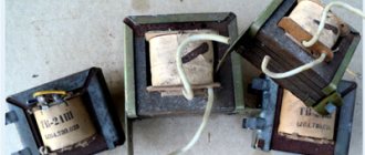
Various models of pulse transformers
Design (types) of pulse transformers
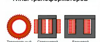
Depending on the shape of the core and the placement of coils on it, ITs are produced in the following designs:
- rod;Design of rod pulse transformer
- armored; Design of a pulse transformer in armored design
- toroidal (has no coils, the wire is wound on an insulated core); Design of a toroidal pulse transformer
- armored rod; Design features of armored rod pulse transformer
The figures indicate:
- A – magnetic circuit made of transformer steel grades made using cold or hot metal rolling technology (with the exception of the toroidal core, it is made of ferrite);
- B – coil made of insulating material
- C – wires creating inductive coupling.
Note that electrical steel contains few silicon additives, since it causes power loss from the effect of eddy currents on the magnetic circuit. In toroidal IT, the core can be made from rolled or ferrimagnetic steel.
The plates for the electromagnetic core set are selected in thickness depending on the frequency. As this parameter increases, it is necessary to install thinner plates.