↑ Theory
Nowadays, you can inexpensively buy microcircuits that allow you to assemble simple and efficient switching power supplies, for example, MC34063
or
LM2576
. There are even calculator programs that help determine the values of parts, or you can use a datasheet. But one small problem arises - you need to wind the inductor, which must have a certain inductance and maintain this inductance at a significant bias current - up to several Amperes.
Unfortunately, the range of ready-made inductors in stores is poor and the required ones are often unavailable. At the same time, you can buy ferrite cores or take them, for example, from dismantled electronic ballasts for fluorescent or halogen lamps. You can determine inductance without special instruments using a computer and the Arta Software
, which I wrote about in previous publications (LIMP is a software RCL meter).
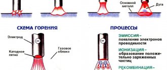
It is more difficult to determine whether the core will go into saturation (and the normal operation of the power supply will be disrupted) or not. Sergey Alekseevich Biryukov, long-time editor of the Radio magazine and author of many articles on the subject of pulse converters
wrote the article “Choke for switching power supplies on ferrite rings.” It has a practical circuit that allows you to see and measure the saturation current on the oscilloscope screen.
The article contains a lot of formulas and tables, but I will try to explain everything unscientifically, using my fingers.
In order to make a choke, you need to calculate or take the required inductance from the datasheet. We take the core on which we will wind the coil and wind several dozen turns with a convenient wire, for example, 0.3 mm. We measure the inductance, then calculate how many turns are needed for the future inductor. To do this, remember that inductance is directly proportional to the square of the number of turns. If 30 turns are wound and the inductance is 20 μH, then to get 180 μH, you need to wind 90 turns.
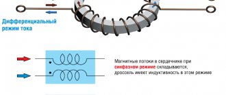
Now let's remember what Ampere-turns are. This is the product of the number of turns and the flowing current. The core will be equally magnetized by 200 turns at a current of 1 A or 1 turn at a current of 200 A, or 50 turns at a current of 4 A. This means that if we find out at what current the core will be saturated from our test coil of 30 turns, we can easily find out what current it will withstand our choke with a working coil of 90 turns.
You just need to remember that it is better to make the inductance a little larger than recommended and that as the number of turns decreases, the inductance drops much faster than the permissible current increases. In addition, to reduce losses, thick wire must be used. It is possible that this core may not be suitable, then, if these are rings, you can add two or three rings or take a different standard size or even connect two chokes in series.
Sequencing
When the necessary tools and materials are prepared, you can begin to manufacture the throttle for welding. The algorithm of actions is as follows:
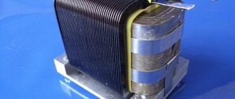
- disassemble the transformer, clean the coils from traces of old windings;
- make gaskets from fiberglass, cardboard impregnated with bakelite varnish, or other suitable dielectrics, which will subsequently play the role of an inductive (air) gap. They can simply be glued to the corresponding surfaces of the coils. The thickness of the gasket should be 0.8-1.0 mm;
- wind a thick copper or aluminum wire onto each coil. You should focus on a round wire made of aluminum with a cross-section of 36 mm or copper with a similar ohmic resistance. Each “horseshoe” is covered with 3 layers of 24 turns each;
- lay a dielectric material between the layers - fiberglass, cardboard impregnated with bakelite varnish or another dielectric. The gaskets must be reliable, since a choke of this design is prone to self-breakdown between windings. If the resistance between the windings is lower than the air resistance between the electrode and the additive, then a breakdown will occur between the windings, and the welding device will be irreversibly damaged.
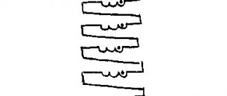
Winding must be done evenly, without overlaps, strictly in the same direction, so that the “bridge” between the coils is on one side of the future inductor, and the input and output contacts are on the other.
In case of an error, the jumper can also be installed askew. It is important that its installation turns coils with different winding directions into coils with the same direction in fact.
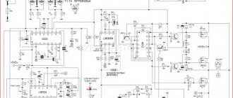
↑ Scheme
I assembled the meter on a small board, the parts are very ordinary, where it is convenient, I install SMD and advise you. Field-effect transistor - any with the required conductivity for a current of 20 A and above, with a low channel resistance in the open state, can be low-voltage. I installed IFRP150. 6 V stabilizer on the 78L06 chip. If it is not there, you can install 78L05 and add 1-2 diodes of the KD522 type into the break of the common wire 78L05 anode to the stabilizer. I installed the C3C4 capacitors at 2200 uF at 35 V. The ratings of the parts are not critical. During the testing process, I realized that a slight modification of the circuit was needed. Instead of VD3 VD4, I installed one D816V zener diode. To increase the current pulse to 12 A, a resistor with a value similar to R5 must be placed between the base and emitter of VT1. These small changes allow ready-made inductors of several millihenries to be tested. I reduced the R4 value by three times, which made the beam on the screen brighter. The signal to the oscilloscope synchronization input is removed from pin 11 of the microcircuit through a 1 kOhm resistor.
Varieties
The following types of electric chokes are currently used:
- Turn-free. A turn-free electromagnetic choke consists of a ferrite ring and a conductor passed through it. It has a great external resemblance to a conventional resistor. The main purpose of the device is to suppress high-frequency interference.
- For alternating current. Designed to create reactive and inductive reactance, a current ripple filter in voltage converters.
- Smoothing. An electronic smoothing choke is used to reduce the variable part of the voltage or current on the input and output parts of the electrical circuit. Such devices are used in current converters. Smoothing chokes are connected in series to the load, thereby causing smoothing of the alternating part of the current, passing through only the direct component of the linear current. A feature of such elements is their high inductance.
- Saturation. The saturation choke is used for alternating current circuits as an inductive reactance regulator. The main difference between the device is the presence of 2 windings: a working winding, for connecting to alternating current, and a control winding, which is connected directly to an electrical circuit with direct current. To operate such a device, a variant of the nonlinearity of the magnetic circuit curve is used. In other words, the DC current regulation depends on the amount of magnetization of the core.
Modern electrical engineering requires a significant reduction in the overall parameters of electrical circuit elements. On surface-mounted circuits, provided they are heavily loaded with parts, so-called chip filters are used. Such elements do not have a wire. The coil is formed from several layers of ferrite. The main purpose of chip filters is to reduce high-frequency interference in complex electronic circuits.
In addition, there are starting devices. They are used as braking and starting current limiters for electric motors. In electrics, three-phase varieties are used to start a powerful electric motor. They are distinguished by a large amount of inductance.
↑ Working with the device
Set R3 to the minimum pulse duration, gradually increasing it, and obtain an image on the oscilloscope screen. First, you can enable continuous scanning and internal synchronization, resulting in an unstable image. Then, having selected the sensitivity and scanning frequency, turn on standby scanning and external synchronization, the picture will look like a glove.
On the oscilloscope S1-94 with a sensitivity of 0.1 V/div, one cell corresponds to a coil current of 1 A. By increasing the pulse duration, we will achieve a break in the pulse shape upwards, read how many cells along the Y axis from below to the break and determine the current. This will be the saturation current.
Options are possible - there will be no fracture, but there will be a triangle that does not grow when turning the R3 regulator. This means there is no saturation, the number of turns of the coil must be increased. Or the shape is not triangular, but smoothed - the active resistance of the coil is high. If you are testing a transformer, be careful, there may be significant voltage on the unconnected windings! And I categorically forbid checking line television transformers or power transformers of computer power supplies in this way! If the coil has an inductance of several millihenries, it accumulates significant energy, which is absorbed by a powerful zener diode (that’s what it’s needed for), and it gets very hot (I smelled it), so measurements of such coils should be short (I slowly set up the oscilloscope with a small impulse, and then I turn the R3 axis and detect the fracture current).
Power on and check
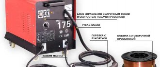
The choke for welding is connected to the system between the diode bridge and ground - a contact that connects to the material being welded.
The output of the diode bridge is connected to the input of the inductor, to the output of the assembled inductor - respectively, a ground contact. The entire assembly for welding must be tested on a piece of metal of the same chemical composition and thickness with which it is planned to carry out most of the welding work in the future. Quality indicators are:
- easy electric ignition;
- arc stability;
- relatively weak crackling sound;
- smooth combustion without strong splashes of melt.
Please note that the introduction of this element into the design of the welding machine leads not only to stabilization of operation, but also to a slight drop in current strength . If the inverter or semiautomatic device begins to cook worse, it means that the current strength has dropped.
The choke needs to be disconnected and a few turns removed from each coil. The exact number of turns in each specific case is selected empirically.
source
↑ Total
For those who work with switching power supplies, this device will be useful. A radio amateur usually makes single devices from assemblies from parts that he can find. I do not agree with those who write that for the LM2576 the inductor can be wound on a nail. It can and will work (due to on-chip limiters and fuses), but it will not be possible to obtain good efficiency and good stabilization. The device, of course, is not essential, but it is cheap, simple and portable, so it is useful to have.
Is it possible to make a transformer from a choke?
It is possible to assemble a high-quality transformer from a choke with your own hands. A certain set of tools will be required, but high-end skills will not.
Radio amateurs often claim that it is impossible to assemble a vehicle from a choke due to lack of space for the secondary winding. But if you work carefully, it can be done. It is worth understanding that the transformer from the available chokes will not have high parameters and can be used in limited areas.