Horizontal directional drilling (HDD) is a progressive technology for trenchless installation of underground utilities. The pipeline is pulled through a well drilled along a curved path under the control of radar systems. Another name for the method is hydraulic directional drilling, since during operation the well is washed with a pressure jet of drilling fluid.
What it is?
Horizontal directional drilling (HDD) is a type of trenchless drilling that helps preserve the surface of the landscape (for example, road surfaces, landscaping elements, etc.). This technique appeared back in the 60s of the last century and is popular today. The technique makes it possible to reduce drilling costs, or more precisely, to restore the landscape after this process.
On average, the cost of work is reduced by 2-4 times.
HDD location system as a management tool
Management in the State National Security Service is a very important point. During operation, the drill is out of sight and reach, and uncontrolled drilling can lead to unpredictable consequences. Therefore, in HDD work, location systems are used to control the drilling process. The location system is a probe, which is located on the drill head, and a special synchronization device with this probe, which is in the hands of the location system operator (locator) on the earth's surface. The probe records all information about the angle and direction of drilling, the number of revolutions and the temperature of the drill head. This information is transmitted to the locator during the drilling process and prevents undesirable consequences.
Advantages of the GSB method
Auger drilling of pipelines is widely used nowadays, because this drilling method allows you to quickly and efficiently do all the work without extra costs. It is installations for horizontal auger drilling that make it possible to carry out complex work on laying wells in urban and other cramped conditions, while simultaneously removing rock and pushing through the casing, which stabilizes the well and prevents its collapse.
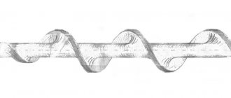
A special feature of such installations is the presence of a screw, which is a steel core with a rod and a steel strip welded onto the core at an angle of 35-60 degrees. During the work, the destroyed rocks are brought to the surface using an auger (essentially, this is a modernized Archimedes screw).
Advantages of horizontal auger drilling:
- conservation of surface soil, environment and infrastructure;
- fast soil treatment;
- creation of channels of different diameters and lengths;
- creation of a highly stable well;
- preventing soil subsidence;
- the ability to work with different rocks, even bulk rocks and metal waste (except rocks), under any weather conditions;
- minimal financial costs.
Drilling fluids for horizontal directional drilling[edit | edit code]
HDD specialists devote a lot of time to improving the quality of flushing fluids when drilling horizontally directed wells. It is known that drilling fluid has a great influence on the productivity and efficiency of the entire process: drilling speed, environmental conditions, and work safety. In HDD, the quality of drilling fluid guarantees 70-80% of the successful completion of work on laying communications.
When working in sandy soils, HDD specialists often encounter the problem of filtration and water absorption, this is due to the properties of the soil itself, since sand is porous and highly permeable by nature. As for shale clays and loams, which are often found in drilling areas, when exposed to water, these types of rocks become sticky and swell. The result of such processes can be loss of fluid circulation, jamming and jamming of the drilling tool, which leads to the impossibility of further work with the so-called “tool stuck”.
To avoid these problems, bentonite drilling fluids and various components are used to eliminate complications, clay inhibitors or stabilizers, lubricating additives for lubricating tools and well walls to facilitate drilling, polymers that thicken the drilling fluid to maintain its required viscosity.
Most HDD operators use bentonite-based “one-bag” multi-component mixtures to facilitate the preparation of low-solids drilling fluid on site.
At large facilities, the solution is prepared individually, according to the geological and technological plan (GTP), the diameter of the pipe being pulled, the composition of the soil, the pump power and the traction force of the installation.
Features of the technology
In simple words, the principle of the method comes down to creating 2 punctures in the ground (pits) and an underground “passage” between them using horizontally inclined pipes. This technology is also used in cases where it is impossible to dig a trench (for example, on historically valuable objects). The technique involves performing preparatory work (soil analysis, preparing 2 sites - at the entry and exit points of the trench), forming a pilot well and its subsequent expansion in accordance with the diameter of the pipes. At the final stage of work, pipes and/or wires are pulled into the resulting trenches.
With HDD, both plastic and steel pipes can be laid in the trench. The former can be fixed at an angle, while the latter can only be fixed along a straight path. This allows the use of polypropylene pipes in trenches under reservoirs.
Horizontal drilling is effective in solving the following problems:
- laying electrical cables, gas and pipelines to objects;
- obtaining wells for oil production and extraction of other minerals;
- renewal of worn-out communications;
- formation of underground highways.
In addition to the indicated savings, this drilling technique has other advantages:
- minimal destruction of the earth's surface (only 2 punctures are made);
- reduction of work time by 30%;
- reduction in the size of the work team (3-5 people required);
- mobility of the equipment, it is easy to install and transport;
- the ability to carry out work in any territory (historical centers, areas where high-voltage lines pass) and soils;
- the ability to preserve soil without damaging its fertile layers;
- carrying out the work does not require a change in the usual rhythm: blocking traffic, etc.;
- no harm to the environment.
The described benefits determine the popularity and widespread use of the HDD method. However, it also has disadvantages.
- Using standard installations for deep drilling, it is possible to lay pipes no more than 350-400 meters long. If you need to lay a longer pipeline, you have to make joints.
- If it is necessary to install longer pipes underground or to pass them at great depths, the trenchless method will be too expensive.
Pipeline laying
The puncture under the railway or road surface is performed first. Next, the well is expanded to the required diameter. At the third stage, pipes are laid using the HDD method.
This is done quite simply: the pipeline is tightened along with the last expansion rimmer. The communication is secured to the expander using special connecting brackets or swivels.
The conductor is first pulled through the finished channel. This is necessary when organizing cable wiring in communications. In this case, the pipeline structure will serve as a protective casing that protects the wiring in the ground from damage.
This technology allows you to quickly, reliably and economically stretch a pipeline through the ground without organizing trenches, which are usually done manually. After laying the pipeline, HDD can be considered complete. At the end, it is necessary to evacuate drilling and other equipment from the work site.
Microtunneling
Microtunneling can be considered a kind of symbiosis of horizontal drilling and punching technologies (of course, very far removed from its ancestors). This method is based on the construction of a tunnel using a remotely controlled tunneling shield extended from a pre-prepared starting shaft. After completion of the excavation (and it can be carried out in a straight or curved direction), it is removed from the receiving shaft.
| Rice. 9. Microtunneling equipment from Herrenknecht AG. | Rice. 10. Trenchless rehabilitation of a water pipeline with a diameter of 1400 mm using PipeWay technology (St. Petersburg Vodokanal State Unitary Enterprise). |
What does the prefix "micro" mean? The Canadian company Lowat classifies equipment for tunnels with a diameter of up to 1500 mm in this class. The Moscow manual on the use of microtunneling complexes and microtunneling technologies in the construction of underground structures and laying communications in a closed way says: “Microtunneling is the process of constructing an underground structure of a circular cross-section with a diameter from 200 to 2000 mm using controlled installations without the presence of people in the face.” However, sometimes tunnels with a diameter of 3000 mm are classified as microtunnels.
Microtunneling differs from punching in its longer length of penetration (up to 500 m, and, if necessary, up to several kilometers), speed and accuracy (regardless of the length of the route, it is controlled by a computer complex using a laser guidance system). And besides, minimizing costs and material resources. The impetus for the accelerated development of this technology in Russia was given not only by the emergence of effective equipment (Lovat, Robbins, Herrenknecht AG), but also by the arrival of qualified specialists from the metro construction industry that closed down its work in the mid-90s.
With the help of microtunneling, you can “break through” soils of any category - from unstable loams and aquifers to rocks, work in a mixed face, and not be afraid of the appearance of coarse inclusions, boulders, pebbles and crushed stones in the soil mass along the route.
A variety of pipes are used for microtunneling: polymer concrete, reinforced concrete, ceramic, fiberglass, asbestos-cement.
Punching
If, when puncturing, the soil displaced from the well is simply “pressed” into the walls of the well, then when pushing, like a core during core drilling, it enters a pipe equipped with a knife, which makes it possible to work with pipes of much larger diameter (up to 2000, and in some cases even 3000 mm). Pushing the pipe, as with a puncture, is carried out with jacks.
Pressure is transmitted through the headrest by replaceable push-on extension pipes, cleaning rods or clamping clamps. The pipe (steel or reinforced concrete) is pressed cyclically by alternately switching the jacks to forward and reverse. Applied force up to 3000 kN. It is possible to use vibration-impact installations, hydraulic scouring, and a combination of a hydraulic monitor that erodes the soil and an auger that removes it.
The pushing length is usually up to 100 m. The penetration speed when using hydraulic jacks is up to 10–12 meters per shift. Work can be carried out either with or without destruction of the old pipe.
Equipment
To carry out HDD, machines and tools are used that can pierce the top layers of soil and go deeper. Based on the volume of work and type of soil, these can be special hammer drills, motor drills or drilling machines. The first 2 options are usually used for personal use, while drilling machines are used on large objects, strong and hard soils.
Cars
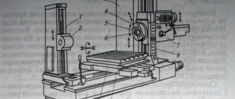
A drilling machine or HDD rig is a type of industrial equipment that runs on diesel. The main functional elements of the machine are the hydraulic station, carriage, and control panel. The latter allows the operator to control the operation and movement of the machine and looks like a special remote control. Directly creating a trench is possible thanks to the drill. During rotation, the drill heats up, which can lead to rapid failure. This can be avoided by regularly cooling the metal part with water. For this purpose, a water supply hose is used - another element of the drilling machine.
Drilling equipment is classified based on the limiting pulling force (measured in tons), maximum drilling length and borehole diameter. Based on these parameters, the drill power is calculated. A more compact analogue of a drilling rig is a motor drill. Its main purpose is to perform small earthworks. However, the piercing part of the drilling process in some cases is quite easily and quickly performed with a motor drill. Since a motor drill operates as an auger, it is often called a press-screw machine. This setup includes a drill, a rod and a motor.
Drilling with a motor drill is possible even by one person; the devices differ in type of power and are divided into professional and for private use.
Location systems
Such a system is necessary for precise control of the trajectory of the drill head and its exit to the location of the second puncture. It is a probe attached to the drill head. Workers monitor the location of the probe using locators.
The use of a location system prevents the drill head from colliding with natural obstacles, for example, dense soil deposits, groundwater, and stones.
Auxiliary Tools
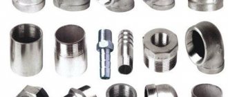
This type of tool becomes necessary at the stage of soil puncture. Rods, threaded screw tools, expanders, and pumps are used. The choice of a specific tool is determined by the type of soil and the stages of work. Auxiliary tools also include clamps and adapters, the main task of which is to help in obtaining a pipeline of the required length. To obtain a channel of the required diameter, expanders are used. Water is supplied to the installation using a pump system. Generators ensure uninterrupted operation of the equipment, and the lighting system allows drilling even in the dark.
Auxiliary tools or consumables include copper-graphite lubricant. It is used to lubricate the joints of drill rods. Horizontal drilling necessarily involves the use of bentonite, the quality of which largely affects the speed of work, the reliability of the trench, and environmental safety. Bentonite is a multicomponent composition, the basis of which is aluminosilicate, characterized by increased dispersion and hydrophilic properties. The remaining ingredients of the solution and their concentration are selected based on soil analysis. The purpose of using bentonite is to strengthen the walls of the trench and avoid soil shedding.
The solution also prevents soil from sticking to equipment and cools rotating elements.
Pros and cons of technology
- The type of soil, landscape and its structure, the presence of reservoirs do not interfere with the process of horizontal drilling. Crowded urban buildings, congested roads or protected natural and cultural areas - this method of laying communications will not harm their condition;
- Less time and effort is spent on obtaining permits for work, since there is no need to block the movement of road and rail transport;
- The costs of attracting heavy equipment and workers to carry out large-scale earthworks are reduced;
- By attracting professional performers and high-tech installations, installation time is minimized;
- The autonomy of drilling complexes eliminates dependence on external power sources;
- HDD can be successfully carried out with high groundwater levels. They do not affect the speed and duration of work;
- About HDD we can conclude that this is minimal harm to nature and humans.
Step-by-step description of the process
HDD is carried out in several stages, and the general scheme of work looks like this:
- preparation of design documents that reflect all necessary calculations;
- coordination of the project with the owner of the site (if it is a private territory) and authorities (if we are talking about carrying out work on municipal facilities);
- digging pits: one at the start of work, the second at the exit point of the pipeline;
- laying the necessary equipment using drilling rigs;
- completion of work: backfilling of pits, if necessary, restoration of the landscape in place of the pits.
Before you drill a hole in the ground, you need to take care of preparing the landscape. To install universal drilling equipment, you will need a flat platform of 10x15 meters, it is located directly above the entry puncture site. You can do it yourself or using special equipment. Make sure that there are detour routes to this site. Afterwards, the drilling equipment is delivered and installed.
In addition to the HDD machine, you will need equipment for preparing bentonite solution. It is used to strengthen the walls of the trench and remove soil from the canal. The installation for bentonite solution is placed at a distance of 10 meters from the drilling machine. Small depressions are created near the intended puncture points in case of excess solution.
The preparation stage also involves installing and checking radio communications between team workers and soil analysis. Based on this analysis, one or another route for drilling is selected. The drilling area should be fenced off with yellow warning tape. The drilling equipment and pilot rod are then installed. It is fixed at the point where the drill head enters the ground.
An important step is securing the tools with anchors to avoid their displacement during HDD.
Upon completion of the preparatory stage, you can proceed directly to drilling. First, a pilot well with a cross-section of 10 cm is formed. Then the equipment is re-debugged and the inclination of the drill head is adjusted - it should have an inclination angle of 10-20 degrees relative to the horizon line. A pilot well is a training perforation, without which trenchless drilling is unacceptable. At this time, the functioning and serviceability of the systems is checked, and the features of the drill’s movement are assessed.
At the stage of forming a pilot well, you need to adjust the tool according to the angle of soil inclination, and also check the location of the drill head in relation to the landscape line. Just in case, bends are formed in the pits. They will be useful if underground water or bentonite liquids are found in large volumes. The latter will prevent the collapse of the trench and the braking of the drill due to soil sticking to it, overheating the equipment.
When preparing, it is important to make accurate calculations so as not to damage previously laid pipe lines. The minimum distance from pipes should be 10 meters. Then the process of moving the drill along a given path begins, and every 3 meters it is necessary to control and adjust the direction of the tool. Once the drill reaches the required depth, it begins to move horizontally or at a slight slope - this is how a trench of the required length is laid. After the drill has passed the required length, it is directed upward, towards the exit. Naturally, the point of the second pit is calculated in advance, and the site is pre-prepared at this point.
The final step is to remove the original tool from the ground and ream the hole using an reamer or reamer. It is installed instead of a drill and allows you to increase the diameter of the pilot channel. During the movement of the expander, monitoring and, if necessary, adjustment of the tool’s trajectory every 3 meters are provided.
The rimmer moves along a trajectory opposite to the direction of the drill, that is, from the second puncture to the first. Depending on the required diameter of the trench, the expander can pass through it several times. The diameter of the channel depends on the diameter of the pipes - on average it should be 25% wider than the diameter of the pipes being laid. If we are talking about heat-insulating pipes, then the width of the channel diameter should be 50% greater than the diameter of the pipes.
If there is a high soil pressure in the channel and there is an increased probability of its collapse, then the bentonite is distributed evenly. After it hardens, not only the risk of shedding, but also soil subsidence is eliminated. For easier entry and passage of the tool through the soil, a special softening drilling fluid is used. With the HDD method, much attention is paid to the risk of soil collapse. In this regard, the strength of the pipe connections is additionally monitored so that they do not rupture under the weight of crumbling soil.
After the horizontal trench is ready, they begin to install pipes in it. To do this, brackets and swivels are attached to it, with the help of which it will be possible to tighten the pipe into the channel. A head is attached to the beginning of the pipe, to which the swivel will be fixed. The pipes are also joined through the swivel, while the drilling equipment itself is turned off. For docking, they resort to the use of special adapters.
For small-sized wells and pulling plastic pipes of small diameter, the force of a drilling machine is used. After laying the pipe in a horizontal trench, the HDD process is considered complete.
SAFETY REQUIREMENTS AFTER WORK COMPLETION
7.1. After completing the installation operation, it is necessary to: - inspect the hydraulic system; — “re-anchoring” the drilling rig; — with the engine turned off, clean and rinse all the tools; — disconnect all hoses and cables; — disconnect the “zeroing” cables and roll up the “zeroing” mat; — roll the unit onto the trailer and prepare it for transportation. - remove personal protective equipment and put it in the place intended for it. 7.2. If the drilling fluid will not be used during the current day, it must be drained and the pumping station flushed with a stream of water or antifreeze (antifreeze) to prevent them from freezing (in winter). 7.3. Before excavating soil from pits that are intended for collecting bentonite, pump out the bentonite solution and transport it for disposal. 7.4. At the final stage of the work, it is necessary to level all excavated soil, remove fences and restore landscaping. 7.5. Inform the work manager or the person responsible for the good condition of the machine about any problems that arise during operation. 7.6. In winter, upon completion of the expansion of the channel, the rods located in the channel should be empty (without bentonite solution). 7.7. Dismantle the construction site. 7.8. Clean up debris at the drilling site (household waste, pipe cuttings, bentonite bags).
We thank Vladislav for the material provided! =)
Types of horizontal drilling and used drilling rigs
Each type of horizontal drilling is good in a certain situation when laying utilities. Some of them are completely interchangeable, and the economic effect achieved when laying pipes plays an important role when choosing a method.
For example, if the project provides for a microtunneling method for laying a steel casing of a water pipeline, and the construction organization has a horizontal directional drilling installation (or a jacking installation and SPK), then, if certain conditions are met, the microtunnel will of course be replaced with HDD or punching of the casing.
So, let's look at each of the horizontal drilling methods in detail.
Horizontal directional drilling
The HDD method, or as it is also called “directional drilling,” is one of the most common methods for laying pressure pipelines and cable cases. This method can also be used for laying free-flow (gravity) pipes, but it has its own characteristics, which you can familiarize yourself with in detail on the page - Trenchless sewer installation using the HDD method.
The well is drilled from the surface of the earth; the diameter of the well should be 30-50% larger than the diameter of the pipe. The well is formed by gradual expansion, using bentonite and polymers. The bentonite solution ensures the removal of drilled soil, the formation of a filter cake, cools the drilling tool, and supports the well to avoid collapse. The spent bentonite solution with soil is pumped out of the working pit using sludge and disposed of in a landfill. It should be noted that a well-formed well (without collapses, blockages, etc.) is the key to success and trouble-free operation.
The length of the laid pipes is from 25 to 1000 meters and above, depending on the traction force and torque of the drilling rig. Pipe diameters from 63 to 1200 mm. Pipe material: HDPE, steel, cast iron.
Horizontal directional drilling along a given trajectory is possible thanks to the location system. The drilling trajectory is limited by the drilling angle (usually 26-34 percent) and the bend radius of the rods. The allowable percentage of bend per rod varies from 6 to 12 percent, depending on the type of rod.
HDD equipment and installations in the modern world are very diverse; the most common manufacturers include Vermeer, Dith With, Tracto-Technik, Robbins, American Augers, Herrenknecht AG, Prime Drilling. Recently, a lot of manufacturers from China and Korea have appeared on the HDD market.
A video that discusses HDD technology in detail, as well as the advantages of this method, is available on the main page of our website.
Controlled puncture
The controlled puncture method is also a subtype of horizontal drilling and is ideal in cases where it is necessary to lay a small diameter pipe (up to 315 mm) in cramped conditions. This method is used to lay polyethylene and steel pipes, cases for gas and water supplies, sewers, telephone and power cables. This type of work is carried out both in large cities and in much smaller settlements, as well as when working under railways and roads.
Controlled piercing is performed using the Ditch Witch P80 piercing unit. The equipment complex consists of the installation itself, a hydraulic station, basic tools for drilling operations (this includes rods, reamers, drill heads and much more), wireless location.
The main part of the installation for controlled puncture is a hydraulic power cylinder with a capacity of 36 tons. The two-cylinder, four-stroke gasoline engine is driven by a hydraulic station.
The GNB-Stroy company uses the Eclipse location system. It consists of a probe located in a removable drill head, and a locator that determines the horizontal location and depth of the drill head, the angle of inclination in the vertical plane, and the battery charge level of the probe. The tip of the drill head has a beveled surface, so that when pressed, the drill string is deflected to the side. Using the locator, the operator can observe how to rotate the head to adjust the trajectory in the desired direction. If you press the rods with rotation, the drill string will move straight.
After horizontal drilling is completed, the drill head goes into the receiving pit, where it is replaced with a conical expander. Then the pilot well is expanded to the required diameter by reversing the rods and compacting the soil. At the same time or after preliminary expansion, a pipe or several pipes are pulled into the finished well.
The directional puncture installation works without the use of bentonite solution. The walls of the well are supported by a compacted layer of soil. The installation can be used not only in summer, but also in winter.
The main characteristics of the controlled puncture installation are its lightness and ease of transportation, compactness, power, direction control and increased electrical safety. The directional drilling unit is very convenient to use when making punctures under roads:
- the starting pit is relatively small in size, 1.5 x 3 m;
- operation does not require water, nor does it require pumping out waste drilling fluid.
Auger drilling
Auger drilling is a trenchless technology for laying pipes using a hydraulic jacking unit, which is equipped with a rotating cutting tool launched from a working pit to remove the developed soil using an auger mechanism. The drilling auger rig allows you to lay steel casings, concrete and polyethylene pipes. Their diameter ranges from 100 to 1720 mm for a length of up to 100 m, depending on the type of soil.
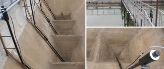
In order to implement the laying of communications, two pits are needed: a starting and a receiving pit, the depth of which is 0.5-1.0 meters lower than the depth of pipe laying. A powerful jacking station is mounted in the starting pit, onto which a drilling mechanism with punching pipes is placed.
At the first stage, the working and receiving pits are prepared. On the second stage, the auger installation is lowered and installed in the pit. On the third stage, the pipeline is being laid, the exact direction of which is controlled by a laser. And finally, completion of the work. The auger is brought into the receiving pit and then pulled out in the reverse order. After which the installation and augers are removed from the starting pit.
Thanks to a special laser control system, horizontal auger drilling technology makes it possible to lay pipes with a given slope with a high degree of accuracy, which is especially important when constructing gravity sewer networks.
AUGER DRILLING
Trenchless laying of communications
Auger technology is an underground method of laying steel pipes. This is necessary, first of all, when laying sewer networks, crossings over roads and railways, and in the area where communications are connected to buildings. Auger drilling rigs allow laying pipes with a diameter of 100 to 2000 mm and a length of up to 60 m. The choice of a specific drilling rig depends on the length and diameter of the drilling
Stages of work: 1. Preparation of starting and receiving pits; 2. At this stage, the GSB installation is lowered into the prepared (starting) pit to a given level, and then a controlled crushing of the pipe is carried out with simultaneous mechanical removal of the developed rock from its cavity using an auger; 3. When the pipe reaches the receiving pit, the punching stops. The auger string and drill head are removed from the casing into the starting pit; 4. Upon completion of the work, the equipment is removed from the starting pit; 5. Dismantling the starting and receiving pits.
The advantages of this technology are:
- High precision allows you to lay gravity sewers and pipelines without deviations;
- Preservation of surface soil, environment and infrastructure;
- Allows the installation of large-diameter pipelines in cramped conditions;
- The operating parameters of our installations allow us to lay pipes with a diameter from 100 mm to 1820 mm over a distance of up to 120 m, depending on the type of soil.
Let's start drilling - important stages of preparation
Do-it-yourself horizontal drilling involves making a puncture using professional equipment. Before you start making a channel under a road or railway tracks, you should prepare for this process. To obtain a drilled hole, it is necessary to level the site on which the equipment will be placed.
The size of the site on which the installation will be placed must be at least 10x15 m. The site is made exactly at the site of the planned puncture under the road. Only after the site of the required size has been prepared can the corresponding equipment and equipment be transported.
After placing the equipment, the anchor installation procedure is carried out, which is implemented using augers. After the anchoring procedure, the process of adjusting the angle of entry of the drill into the ground is carried out.
It is also necessary to first prepare an installation that prepares the bentonite solution. This solution is mixed by a special machine, which should be placed next to the drilling mechanism. The distance between these devices must be at least 10 meters. A bentonite solution is used to strengthen the walls of the well, as well as to remove soil from the channel being drilled.
The preparatory process also includes the following activities:
- Construction of special pits at the entrance and exit of the canal. Excessive amounts of solution will move into these wells.
- Determine the presence of underground communications that should not be affected by the drilling rig.
- Study the nature of the soil, on the basis of which a decision will be made to select the optimal route for drilling.
- Set up communication between the foreman and the equipment operator.
How the process itself will go depends on the preparation stage, so this event should be treated with particular importance. When drilling, safety precautions are observed, on which the health and life of workers depends.
Trenchless pipeline repair methods
These technologies appeared in the middle of the last, 20th century, but their importance is only increasing every year, and especially for our country. The reason is the extremely poor state of engineering networks. According to statistics, the average number of emergency damages to pipelines per unit length in the Russian Federation is at least twice as high as in the countries of Western and Central Europe. The need to prevent premature failure of utility pipelines and promptly eliminate emergency situations has raised the importance of trenchless methods for their repair as never before. The most popular today are three of them:
Description of auger drilling technology
First, a pilot well is constructed using pilot rods 1 m long and 114 mm in diameter. Thanks to optical navigation, the construction of a pilot well occurs with pinpoint accuracy. Further, the laid “pilot” serves as a guide for 3-meter augers inserted into corresponding 3-meter sections of a steel case of the required diameter, which, as it moves forward, is expanded with 3-meter pipe sections. The sections of the case are welded together as they go.
The use of hollow shaft augers has significant advantages, since this system allows controlled drilling without digging a reception pit. How is this achieved? Everything is quite simple, the pilot pipes are not pushed out by the augers, but the augers “run” onto the pilot pipes, because The diameter of the auger shaft is slightly larger than the diameter of the pilot rods.
After the installation of the casing is completed, the pilot pipes and augers are removed to the surface, into the working pit. This technology has an invaluable advantage for making taps into existing wells of any diameter, even 1 m, since it does not require removing pilot pipes and augers from the original well.
Another added benefit is the ability to overcome obstacles encountered during pilot drilling. To do this, hollow augers, inserted into pieces of steel case, are put on pilot pipes and the well is drilled to the obstacle. Next, the pilot, together with the hollow augers, is pulled back into the starting pit. After this, the obstacle is removed in one way or another, after which pilot drilling can be resumed, without the need to excavate a pit at the site of the collision with the obstacle.
The equipment is characterized by compactness and a special drive design that transmits rotation directly to the drill string without the use of a gearbox. The specially designed hydraulic control unit and hydraulic station are well suited to the operation of the auger installation, ensuring efficient and energy-saving operation on the construction site.
Advantages of the auger method
Trench technology for laying communications is considered obsolete for economic and production reasons. The first benefit of auger horizontal drilling is the volume of work and the amount of required labor resources. The drilling rig can be operated by one team of workers, and the volume of excavated earth is much less. At the same time, construction time, depending on the length of communications, is reduced by 2-20 times.
Economic costs for horizontal directed work are reduced by 30%. In this case, there is no need to interrupt traffic flow when laying pipes under roads or rivers, and the railway and asphalt tracks remain intact.
During drilling, the environment does not suffer, and the process itself causes minimal inconvenience to people. The risk of accidents on site is minimized through the use of steerable drill heads.
The disadvantage of horizontal drilling technology is the inability to work on moving soils.
Channel expansion - the final stage
As soon as the pilot channel is completed, you need to begin the procedure for expanding it. The drill head is dismantled and a rimmer must be installed in its place. This is an important structural element of the installation, which is used for laying the pipeline using the horizontal method. This device serves to expand the pilot channel.
The rimmer helps increase the diameter of the channel in the return path, that is, from outlet to inlet.
Depending on the task of obtaining the diameter of the hole, increasing the size of the channel can occur several times.
Increasing the size of the well is carried out before communications are laid. During the work process, it is imperative to ensure that coolant is supplied to the drill. Interruptions in the supply of coolant will lead to overheating of the installation and failure of geolocation equipment.
Scheme of work.
Stage 1: controlled pilot drilling
With controlled pilot drilling, the axis of the subsequently laid pipe is set. The installation operator continuously monitors the position of the pilot head with the PERFORLUX diode target through the monitor and has the ability to immediately respond to any deviations from the specified drilling trajectory. The length of pilot drilling varies for different PERFORATOR installations and can reach 120 m. In difficult-to-compact soils, supplying bentonite solution through a two-pipe pilot rod reduces friction and helps to achieve specified drilling lengths. An important element during pilot drilling is the navigation system consisting of a PERFORLUX diode target located in the pilot drilling head, a camera and a monitor.
(View 2) Using these elements, the operator controls the position of the drill head and holds the pilot rods on the specified drilling axis. In case of deviation (View 1), the operator rotates the pilot drill head to the desired position (View 2) and presses the pilot rods into the ground without rotation. The beveled plane of the pilot drill head allows it to be returned to the drilling axis (View 3). Thus, horizontal drilling is carried out with high precision.
(View 2)
Appearance of navigation system elements
| PERFORLUX diode target | Camera | Monitor |
The pilot drilling tool consists of the following elements:
- Pilot drill head;
- Rod with PERFORLUX diode target mount;
- Pilot rods, in the quantity necessary to achieve the required drilling length
- Flushing head required to feed bentonite to the pilot drill head
In poorly compacted soils, pilot drilling is very difficult due to the strong compression of the pilot rods and the high resistance to both their punching and rotation. To lubricate the pilot rods and reduce pushing friction, a bentonite solution is required to be supplied to the pilot drill head. The two-pipe design of the PERFORATOR pilot rods allows not only to pass the diode target beam from the PERFORLUX to the chamber, but also to supply the bentonite solution to the pilot drill head.
Then the bentonite mixture enters the pilot drilling head and is fed into the soil through nozzles, erodes it, and also lubricates the surface of the pilot rods, thereby reducing the friction of the pilot rods on the ground and allowing pilot drilling to be carried out for a length of up to 120 m.
Stage 2: Expansion and pressing of laid pipes
At the 2nd stage of work, an expander is attached to the pilot rods laid along the drilling axis, connecting the pilot rods and the pipes being laid. The operator presses the pipes in the direction specified by the pilot rods, and the soil falling inside the pipe is crushed by the drilling head and transported by augers through the pipes to the starting pit. Pilot rods keep the pipes from moving from the drilling axis, are gradually squeezed out as the length of the pipe increases and are dismantled from the receiving pit. To reduce the friction of the pipes being laid on the ground and reduce the push-out resistance, a bentonite solution is supplied to the outer side of the pipes through a small tube welded to the pipes being laid. It is important to choose the right consistency and composition of the bentonite mixture depending on the type of soil. This can be a decisive factor for the successful installation of the pipeline.
Sequence of work
Using a grinder or grinder, sharpen a piece of reinforcement up to 2 m long, which must be sharpened evenly. If you use reinforcement longer than 2 m, it will bend.
Then you can start drilling. To do this, a sharpened piece of reinforcement is driven into the ground with a sledgehammer in the desired direction.
After the entire segment is hammered in, the next piece of reinforcement is welded to it. This allows you to go deep to the desired depth. If the rod rests against the rock, you can bend it, but you need to be very careful. The process will end once a pointed part of the reinforcement appears at the output. This is how the guide rod is formed.
Next, they take a pipe with a larger diameter and put it on the fittings. Another pipe (drill glass) is put on top of it, which will not allow it to be flattened by impacts; after driving, the glass is removed. The pipe is also sharpened with a grinder so that it goes into the ground more freely.
After driving the pipe to a depth of 2 m, a pump is installed into it and water is supplied. To increase pressure, you need to use nozzles with a smaller diameter. Water will flow from the open part of the pipe, for which a barrel with a volume of 150 liters or more will be used.
When the work is completed, the barrel is removed and emptied. Then you can weld another section and continue the process with your own hands until the pipe appears on the other side.
HDD
Horizontal directional drilling (HDD method) is a way to lay various communications underground using a trenchless method. When using the method, the landscape surface remains untouched, including landscaping elements, road surfaces, buildings and other objects. At the moment, several proven methods of horizontal directional drilling have been developed, which are actively used to reduce the cost of laying communications and preserving objects on the surface of the earth.
Sources
- https://stroy-podskazka.ru/bury-dlya-zemlyanyh-rabot/o-gorizontalnom-burenii/
- https://www.prof-tm.com/buroshnek
- https://gnbs.ru/baza-znaniy-po-tehnologii/gorizontalno-napravlennoe-burenie/gorizontalnoe-shnekovoe-burenie-tehnologiya-metoda
- https://specingtonnel.ru/nashi-uslugi/gorizontalnoye-shnekovoye-bureniye/
- https://library.stroit.ru/articles/gnb/
- https://ingestroy.ru/buroshnek/
- https://gnb-stroy.com/services/gorizontalnoe-burenie
- https://FB.ru/article/466739/gorizontalnoe-shnekovoe-burenie-tehnologiya-etapyi-preimuschestva
- https://perforator.su/tekhnologiya.html
[collapse]