Information about the manufacturer of the screw-cutting lathe 16K20
Manufacturer of the screw-cutting lathe 16K20 - Moscow Machine Tools named after. A.I. Efremova , founded in 1857.
The first universal screw-cutting lathes with a gearbox for the first time in the USSR began to be produced at the Moscow Machine Tool Building named after. A.I. Efremov in 1932 and received the names DIP-200, DIP-300, DIP-400, DIP-500 ( DIP
- Catch up and Overtake), where 200, 300, 400, 500 is the height of the centers above the frame.
Machine tools produced by the Moscow Machine Tool Plant Krasny Proletary, KP
- 1A62
- universal screw-cutting lathe, Ø 400 - 1K62
- universal screw-cutting lathe, Ø 400 - 1K62B
– high-precision universal screw-cutting lathe, Ø 400 - 1K282
- eight-spindle vertical lathe, Ø 250 - 1K620
- universal screw-cutting lathe with variator, Ø 400 - 1K625
- lightweight screw-cutting lathe with an increased line of centers, Ø 500 - 16A20F3
– CNC lathe, Ø 400 - 16B20P
- high-precision screw-cutting lathe, Ø 400 - 16K20
– universal screw-cutting lathe Ø 400 - 16K20VF1
- universal high-precision screw-cutting lathe with digital display, Ø 400 - 16K20M
- mechanized screw-cutting lathe, Ø 400 - 16K20P
- high-precision screw-cutting lathe, Ø 400 - 16K20PF1
- high-precision screw-cutting lathe with digital display, Ø 400 - 16K20F3
- CNC lathe, Ø 400 - 16K20F3S32
- CNC lathe, Ø 400 - 16K20T1
- lathe with operational control, Ø 500 - 16K25
- lightweight screw-cutting lathe with an increased line of centers, Ø 500 - 162
— universal screw-cutting lathe, Ø 420 - 1622
— universal screw-cutting lathe, Ø 120 - 1730
— semi-automatic multi-cutting lathe, Ø 410 - DIP-40 (1D64)
- universal screw-cutting lathe, Ø 800 - DIP-50 (1D65)
- universal screw-cutting lathe, Ø 1000 - DIP-200
– universal screw-cutting lathe, Ø 400 - DIP-300
– universal screw-cutting lathe, Ø 630 - DIP-400
– universal screw-cutting lathe, Ø 800 - DIP-500
– universal screw-cutting lathe, Ø 1000 - MK6046, MK6047, MK6048
- universal screw-cutting lathe, Ø 500 - MK6056, MK6057, MK6058
- universal screw-cutting lathe, Ø 500 - MK-3002
- table lathe, Ø 220
Screw-cutting lathe 16K20 - repair of a transverse sliding pair (caliper, cross member, wedge).
A private enterprise repairing metalworking equipment asked for technical assistance in restoring the sliding pair of the carriage and cross member of the 16K20 machine, as well as manufacturing a new wedge
The problem occurs quite often - uneven wear of the guides (0.3-0.7 mm), displacement of the cutter axis
Before contacting us, the customer turned to grinders for help, but was faced with the following problem: the grinding resource of these slides had already been exhausted. The cross member began to rub the support along the area with mark A, which would also have to be ground negatively, and this would already violate the integrity of the factory design of the machine element, as well as subsequent difficulties with aligning the cutter axis with the spindle axis
We proposed to solve this problem by “building up” sliding surfaces with Moglice P 1130 material maintaining all accuracy standards
After inspecting the components and measuring the existing wear, we received impressive (frightening) numbers: deviation from flatness up to 1 mm per 1000 mm.
The process of restoring the sliding pair took 4 working days.
Materials and tools used:
= acetone as a degreaser and cleaner
— 1417 Reiniger Fl – finishing, specially developed Diamant cleaner. Reliably removes grease, oil and coolant residues, creating an ideal surface for all Diamant products. A
machine guides are prepared for application of Moglice P 1130
— 1354 Trennmittel Fl – a special release agent that allows you to create a reliable separation layer with a thickness of a micron. Reliable, because not all separators work well - “sticking” may occur and the work will go down the drain. Trennmittel follows the forming surface with micron accuracy and sticking is eliminated.
= Moglice P 1130 – 2 mm layer applied. This is enough for reliable long-term operation. See about the material here: https://remval.by/category-products/moglice-pretsizionnye-iznosostojkie-pokrytiya-skolzheniya/
- a specially ground ruler made from available material (in our case, a channel), the ruler can be used repeatedly to shape the surface.
molding using a ground ruler
— grinder and clamps 2 pcs.
One guide is molded
one machine guide is molded
Below is a photo of the finished guides:
refurbished machine guides using Moglice P 1130
guides are formed immediately with lubrication channels
The technology is not complicated; any repair service of the enterprise can master it.
An additional bonus of this method is that we did not have to make a wedge with new parameters; it was enough to update the planes of the existing wedge.
The lubrication channels are also made using the imprint method, but can be cut into the moglies if desired.
Labor warranty 1 year. But Moghlais goes through much more Leave a request
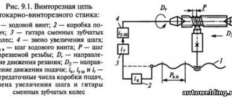
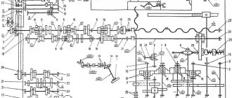
Kinematic diagram of a screw-cutting lathe 16K20
Technical specifications, drawings and descriptions of components are given on page 16K20 .
16K20 screw-cutting lathe replaced the legendary but outdated 1K62 machine in 1972. The 16k20 machine is superior to the 1K62 model in all quality indicators (productivity, accuracy, durability, reliability, etc.).
In 1988, the 16k20 was replaced by the more modern MK6056, MK6057, MK6758.
The kinematic diagram of the 16k20 is given to understand the connections and interaction of the main elements of the machine. The numbers of teeth (z) of the gears are indicated on the callouts (the asterisk indicates the number of worm runs).
Kinematic diagram of a screw-cutting lathe 16K20
Kinematic diagram of the spindle head of a 16K20 screw-cutting lathe
Block diagram of the gearbox of a screw-cutting lathe 16K20
Block diagram of the gearbox of a screw-cutting lathe 16K20
The main movement drive consists of a single-speed three-phase asynchronous electric motor and a stepped mechanical gearbox. From the electric motor Ml with ndv = 1460 rpm (Fig. 4.3), through a V-belt drive with pulley diameters Ø 140 and Ø 268 mm, shaft I of the gearbox rotates, on which freely rotating gears with a number of teeth z = 56 and z = 51 are installed. for forward spindle rotation (clockwise) and z = 50 for reverse spindle rotation (counterclockwise).
Direct or reverse rotation of the spindle is activated using a double friction clutch Mf1.
Shaft III receives two rotation speeds through wheels z = 34 or z = 39.
Next, using gears z = 29, z = 21 or z = 38 and engaging with one of the corresponding rims z = 47, z = 55 or z = 38 and forming a triple block, shaft IV is driven into rotation.
From shaft IV, rotation can be transmitted directly to the spindle: through gears z = 60 or z = 30 to a block with z = 48, z = 60 or through shafts V and VI, which together with the gears form a pick-up group. In this case, rotation is transmitted by gears z = 45 or z = 15 (on shaft IV), engaging with one of the block rims z = 45, z = 60 (on shaft V), and pairs of wheels 18/72 and 30/60.
In addition to the gearbox, a buster . By brute force we mean an additional gear train, with the help of which an increase in the number of spindle speeds is achieved. In addition, the presence of overdrive makes it possible to obtain low speeds and, accordingly, high torque values on the output shaft of the box.
The minimum and maximum frequencies of direct rotation of the spindle are determined:
Where:
η is the slip coefficient of the belt drive, in calculations we take η = 0.985
ndv - rotation speed of the electric motor ndv = 1460 rpm
140/268 - the ratio of the diameter of the transmitting pulley to the diameter of the receiving pulley. Drive pulley diameter Ø 140, Driven pulley diameter Ø 268 mm
It should be noted that when calculating the spindle rotation speed using the equations of the kinematic chains of the gearbox, the result may not coincide with the spindle rotation speeds indicated in the technical characteristics of the machine, calculated theoretically according to the laws of the geometric series (GOST 8032-84).
Kinematic chains of forward and reverse rotation of the spindle
Spindle speed chart for screw-cutting lathe 16k20
Depending on the options for including gears in the gearbox, you can get 22 different spindle speeds.
Design of a screw-cutting lathe model 16K20
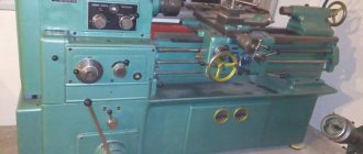
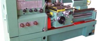
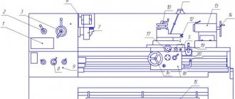
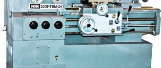
Screw-cutting lathes belong to the group of universal machines designed for use in single-unit and small-scale production. These machines have almost the same type of layout, an example of which is the layout of units and parts of the machine model 16K20 (Fig. 1.10).
Rice. 1.10. General view of the screw-cutting lathe model 16K20
The machine model contains brief information about the machine itself. The first digit, in accordance with the national classification of metalworking equipment given in Appendix 1, indicates the number of the group to which the machine belongs. The number “1” in the machine model 16K20 indicates that this machine is classified as a lathe group of machines. The second digit of the model characterizes the machine type number within the group. According to the data in Table Appendix 1, the 16K20 machine belongs to the sixth type of machines of the turning group - lathes and screw-cutting lathes. The letter between the numbers (in the machine model 16K20 the letter “K”) indicates that the machine has been modernized in relation to the previous model of machines of this group and type. The last two digits of the model in the form of the number “20” characterize the height of the spindle axis above the bed guides (the height of the centers) equal to 200 mm. This means that the diameter of the workpiece processed on the 16K20 machine cannot exceed 400 mm.
The main parts of the machine are the bed 1
, headstock
4
, spindle
5
, caliper
12
, apron
6
, feed box
3
, replacement gears
2
, tailstock
13
, caliper quick movement mechanism
16
.
Bed 1
installed on the left
18
and right pedestals
17
and serves for mounting the main components and parts of the machine on it. The bed is equipped with guides along which the caliper and tailstock move.
Headstock 4
designed to accommodate a gearbox, with the help of which the frequency and direction of rotation of the spindle are changed
5
.
Various devices are installed on the right end of the spindle, which is a hollow shaft, to secure the workpiece. In Figure 1.10, such a device is a three-jaw self-centering chuck.
Caliper 12
The machine consists of longitudinal
7
and transverse
8
slides, an upper support
10
and a four-position rotary tool holder
9
. The cutters are installed and secured in the tool holder, to which, together with the support, the movements of the longitudinal and (or) transverse feed are communicated.
Feed box 3
designed to change the speeds of the longitudinal and transverse feed movements of the caliper, with which it is connected via a lead screw
14
and a lead shaft
15
. The transmission of rotational motion of the output shaft of the feed box to the caliper mechanisms through the lead screw is used only when cutting threads. For all other types of turning work, the movement from the feed box to the caliper comes through the drive shaft.
Guitar replacement gears 2
is a link in transmitting motion from the machine spindle to the feed box and is adjusted when cutting precise threads. By replacing some guitar gears with others, you can change the amount of caliper feed.
Apron 6
is designed to accommodate mechanisms that ensure the conversion of the rotational motion of the running shaft
15
or lead screw
14
into the rectilinear translational movement of the caliper.
Tailstock 13
used as an additional support for the workpiece in the manufacture of shafts with a length-to-diameter ratio of the workpiece of more than four, as well as for fastening drills, countersinks, reamers, taps and dies.
These tools, installed in the retractable tailstock quill 11
, are provided with a feed movement when processing holes located along the axis of rotation of the workpiece by rotating the handwheel with handle
P1
(see Fig. 1.10).
Drive for quick movement of the caliper 16
used to reduce unproductive time spent on auxiliary movements of the caliper. The drive mechanism consists of an electric motor mounted in the rear stand of the frame and a V-belt drive, which transmits rotation to the running shaft.
Turning fixtures
Various devices are used to install and secure workpieces on lathes (Fig. 1.11).
Rice. 1.11. Accessories for lathes:
A) -
three-jaw self-centering chuck;
b) -
ordinary center;
c)
- rotating center;
d)
- driving cartridge;
d)
- fixed steady
The main types of devices include: two-, three- and four-jaw chucks, collet and drive chucks (Fig. 1.11, d
) cartridges, centers (Fig. 1.11,
b
,
c
), steady rests. The chucks are mounted on the machine spindle, and the centers are installed in the tailstock quill or in the machine spindle hole.
Jaw chucks are divided into self-centering ones, which ensure that when securing a workpiece having a cylindrical surface (external or internal), its axis coincides with the axis of the machine centers, and simple ones, which do not implement this function.
Self-centering chucks in most cases are made with three-jaw (Fig. 1.11, a)
and less often - two-cam. Chucks of this type are convenient to use, since all the cams that secure the workpiece move along radial grooves towards or away from the center simultaneously and synchronously with each other. When using self-centering chucks, the time required to secure the workpiece is significantly reduced.
Simple (non-self-centering) chucks are usually made with four-jaw chucks. Each cam in them moves with its own screw independently of the others. This allows you to install and secure workpieces of cylindrical and non-cylindrical shapes in the chucks.
When processing long and non-rigid workpieces on lathes, steady rests are used. Lunettes are divided into fixed ones (Fig. 11.1, d
), fixed on the machine bed, and movable, mounted on a support. The fixed steady rest does not change its position relative to the machine when processing the workpiece. The movable rest, used for longitudinal turning, moves along with the support. Processing of workpieces of asymmetrical shapes is carried out using faceplates, squares, mandrels and other various special devices.
Feed motion and thread cutting
The feed drive includes the following chains and components (see kinematic diagram):
- Thread pitch increasing link - provides an increase in the output rotation speed relative to the spindle speed in the ratio: 1:2, 1:8, 1:32. Provides a double block in the spindle head when connecting z = 45/45;
- Reverse mechanism - serves to change the direction of movement of the caliper with the same direction of spindle rotation. It is carried out by connecting the intermediate gear - snaffle;
- Guitar of replacement wheels - includes replacement gears K, L, M, N. Serves for relatively rare reconfiguration of speeds;
- Feed Box - The feed box receives movement from the headstock through the guitar and sets different rotation speeds for the lead shaft and lead screw;
- Feed mechanism - converts the rotation of the drive shaft into translational movement of the caliper, longitudinal, transverse or cutting slide. The lead screw must be turned off.
- The feed mechanism when cutting threads with a cutter converts the rotation of the lead screw into forward longitudinal movement of the caliper.
Kinematic diagram of the support and apron of the machine 16K20
Block diagram of feeds and thread cutting of a screw-cutting lathe 16k20
The feed movement is borrowed from the spindle in the spindle head when the z = 60/60 pair is running.
If it is necessary to increase the pitch, the movement is borrowed from shaft III with gear z = 45/45 engaged. In this case, the feed and thread pitch increase depending on the position of the blocks in 2; 8 and 32 times.
The reverse mechanism ensures right rotation of the lead screw through a pair of z = 30/45, left rotation through a gear z = 30/25 25/45.
When the machine leaves the factory, gears with a number of teeth z = 40/86, z = 86/64 in the replacement wheels K/L, M/N . This combination provides feeds and cutting of metric and inch threads in steps, the values of which are indicated in the table attached to the machine.
Kinematic chain of longitudinal and transverse feeds of the caliper
The kinematic feed chain coordinates the rotation of the spindle with the movement of the caliper in the longitudinal or transverse directions: for 1 revolution of the spindle, the caliper must move by an amount S.
Kinematic chain of longitudinal feeds of the caliper
The kinematic balance equation for the longitudinal feed chain has the form:
S = 1 rev. sp. · z1/z2 · π · m · z mm/rev ,
Where:
- z1/z2 — gear ratio of the feed drive from the spindle to the rack wheel;
- π·m·z is the length of the pitch circle of the rack and pinion wheel. π m z = 3.1416 3 10 = 94.248;
- m - rack module, m = 3 mm;
- z is the number of teeth of the rack and pinion wheel, z = 10.
The universal feed box 16B20P.070 provides longitudinal feeds (22 pcs), mm/rev:
- 0,05; 0,06; 0,075; 0,09; 0,1; 0,125; 0,15; 0,175; 0,2; 0,25; 0,3; 0,35; 0,4; 0,5; 0,6; 0,7; 0,8; 1; 1,6; 2; 2,4; 2,8; 2,4; 2,8
The equation of the kinematic chain to obtain the minimum longitudinal feed can be written in the following form:
Kinematic chain of transverse caliper feeds
The equation for the kinematic balance of the cross feed chain has the form:
S = 1 rev. sp. · z1/z2 · р mm/rev ,
Where:
- z1/z2 — gear ratio of the feed drive from the spindle to the rack wheel;
- p — pitch of the cross-feed screw, p = 5 mm
The complete kinematic balance equation for the minimum cross feed chain is:
Accordingly, the kinematic chain of the transverse feed coordinates the rotation of the spindle and the transverse lead screw; the amount of transverse feed with the same machine setup is 1/2 of the longitudinal feed.
The kinematic chain equation for obtaining the maximum lateral feed can be written as follows:
In the feed box of a 16k20 screw-cutting lathe, the feeds are not located in a geometric row, so the machine is set to the required feed according to the tables located on the headstock panel.
In the case of cutting precise threads, rotation can be transmitted from the replacement wheels directly to the lead screw with a pitch of t = 12 mm through shafts XII, XVII, XXIII with gear couplings M2 and M5 engaged, bypassing the feedbox mechanism.
and transverse feeds (24 pcs), mm/rev:
- 0,025; 0,03; 0,0375; 0,045; 0,05; 0,0625; 0,075; 0,0875; 0,1; 0,125; 0,15; 0,175; 0,2; 0,25; 0,3; 0,35; 0,4; 0,5; 0,6; 0,7; 0,8; 1; 1,2; 1,4
Kinematic chain for cutting metric threads
When cutting a thread, in one revolution of the spindle, the support (cutter) must move by the thread pitch Рр.
The kinematic balance equation for the metric thread cutting chain has the form:
S = Рм = 1 rev. sp. · z1/z2 · Рх mm/rev ,
Where:
- z1/z2 —gear ratio of the feed drive from the spindle to the lead screw;
- Px is the pitch of the machine lead screw in mm (Px = 12 mm).
Kinematic balance equation for cutting metric threads with a minimum pitch:
Kinematic chain for cutting inch threads
When cutting inch threads, the pitch is specified by the number of threads per inch, all thread parameters are expressed in inches (inch = 25.4 mm).
For inch pipe threads, the size in inches conventionally characterizes the clearance in the pipe, and the outer diameter is, in fact, significantly larger.
Inch thread pitch in millimeters:
Pd = 25.4/k mm/rev,
Where:
- k - number of threads per inch of thread (1″ = 25.4 mm);
Kinematic balance equation for cutting inch threads with a minimum pitch:
Kinematic chain when cutting modular threads
Modular threads are usually used when cutting worms.
The pitch of a modular thread is expressed through the module - a number that is a multiple of pi (3.14).
Modular thread pitch in millimeters:
Pm = 3.14 m mm,
Where:
- m is the thread pitch in modules;
Setting up a lathe for thread cutting
When cutting threads, the equations of kinematic chains are compiled based on the condition that during one revolution of the spindle the tool must move in the feed direction by the pitch Pp of the thread being cut.
Let us write the kinematic balance equation for cutting metric threads with a minimum pitch:
When cutting a modular thread with a minimum pitch, instead of replacement wheels z = 40-73, 73-64, wheels z = 60-73, 86-36 should be substituted into this equation. The kinematic balance equation for cutting inch threads in general form:
Setting up a modern universal screw-cutting lathe 1K620
for thread cutting comes down to setting up the drives of the main movement and the feed movement.
Setting the feed box to the pitch of the thread being cut is in most cases carried out using a table mounted on the machine, or according to a passport.
The feed box control handles are set to the position indicated in the table, and the reverse of the lead screw is set to the position corresponding to cutting a right-handed or left-handed thread, and, if necessary, turn on a link for increasing the thread pitch.
Rotation from the feed box is imparted to the lead screw, and the longitudinal movement of the caliper with the threaded cutter is activated when the split nut is closed.
When cutting high-precision threads or with a non-standard pitch, adjusting the longitudinal feed chain requires preliminary calculations, sometimes quite complex (for example, when adjusting a screw-cutting chain not with a feed box, but with a guitar of interchangeable wheels). Modern universal lathes provide the ability to completely disable the feed box; The driven shaft of the guitar is connected directly to the lead screw of the machine. In these cases, it is necessary to select replacement wheels from those included with the machine or make additional ones. The number of teeth on replacement wheels can be selected in two ways.
In the first method, the feed box levers are placed in a position in which the cut pitch is equal to the pitch of the machine lead screw. Thus, the gear ratio is equal to the pitch of the threaded screw divided by the pitch of the lead screw. In cases where the numerator or denominator of the gear ratio of a simple fraction will have factors that are inconvenient for converting them into the number of teeth of replacement gears, the calculation should be carried out using tables of gear ratios.
In the second method, the selection of replacement wheels is carried out according to one of the gear ratios of the replacement wheels available (even from other machines), or according to the gear ratio of the feed box.
If it is necessary to produce a thread with small pitch tolerances, and the machine lead screw has a manufacturing error, then the selection is performed using approximate methods.
Kinematic diagram of a screw-cutting lathe 16k20
Kinematic diagram of a screw-cutting lathe 16k20
Design of the spindle (front) headstock with gearbox
Gearbox of screw-cutting lathe 16k20
Spindle head of screw-cutting lathe 16k20
All gearbox shafts and the spindle rotate on rolling bearings, which are lubricated both by splashing (the gearbox is filled with oil) and by force, using a pump. The feed movement from the spindle is transmitted to the bit shaft and then to the feed mechanism.
Spindle revolutions per minute - forward rotation (22 pcs): 12.5-16-20-25-31.5-40-50-63-80-100-125-160-200-250-315-400-500 -630-800-1000-1250-1600.
Spindle revolutions per minute - reverse rotation (11 pcs): 19-30-48-75-120-190-300-476-753-1200-1900.
The spindle and all shafts are mounted on rolling bearings. The front spindle support contains a radial double-row roller bearing, in which preload is created by fitting the inner ring onto the tapered journal of the spindle. If you push the ring onto the cone with a nut, it expands and puts pressure on the rollers.
The rear spindle support has two angular contact ball bearings that absorb radial and axial loads; The preload is adjusted with a nut tightening the inner rings.
Shafts II…V of the gearbox are mounted on tapered roller bearings, which is convenient for assembly and disassembly; the preload is adjusted using pressure screws 3. Since shafts III and IV are long, a middle support is provided for them.
On the left side of the friction clutch 13, which reverses the movement of the spindle, there is a large number of disks, since large torques are required in the forward direction of rotation. A special feature of gear blocks is the adhesive connections between the rims and the hubs.
The wheel hub Z= 60 on shaft III is a band brake disc; The rod of the control mechanism, setting the clutch in the neutral position, turns on the brake (by pressing roller 1).
Areas of use and modification of the 16K20 machine
You can download the passport of the 16K20 screw-cutting lathe for free in pdf format here: Passport 16K20
The screw-cutting lathe model 16K20 belongs to the category of universal equipment for processing metal parts. Its characteristics, of course, do not allow it to replace milling equipment, but make it possible to use it to perform a whole list of specialized operations. Such operations, in particular, include cutting threads of various types (metric, inch, modular, pitch), drilling, countersinking and other types of turning.
The capabilities of this screw-cutting lathe are such that it can be used to process workpieces from both hot-rolled and cold-rolled steel. Before the appearance of this machine, enterprises used the 1K62 equipment model, which is significantly inferior to it in all its characteristics. Thus, the advantages of the 16K20 screw-cutting lathe (compared to the previous model) include:
- operational safety;
- high reliability;
- the ability to process parts with high precision;
- simplicity and ease of maintenance;
- exceptional durability even with active use;
- high performance.
Read also: Press rolling machine for rotary drawing of metal
Screw-cutting lathes 16K20 are used in enterprises that produce products individually or in small batches, as well as in tool shops, where such equipment can be used to perform both semi-finishing and finishing work.
Among the design features of this screw-cutting lathe, the following can be noted.
- The equipment frame is made in a box-shaped form and installed on a massive monolithic base, which gives high rigidity to the entire structure. Precision movement along the caliper frame and movable tailstock is ensured by reliable guides, which are heat-treated and ground.
- Depending on the type of processing and configuration, the workpieces can be fixed in the chuck or clamped in centers.
- The cutter holder device is designed to ensure reliable fixation of the tool.
- To install the spindle, high-precision (precision) rolling bearings are used, which are necessary for the accuracy of its location and rotation.
- The design of the 16K20 screw-cutting lathe provides a number of blocking and fencing technical elements that ensure safe work on it.
- To ensure processing accuracy, the machine is equipped with rulers with sights, which can be used to control the longitudinal as well as transverse movements of the tool.
- You can urgently turn off the support feed of a 16K20 machine using a special device installed on the apron of the machine.
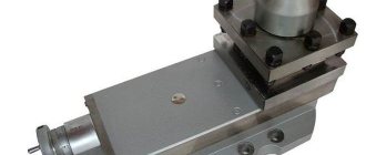
The 16K20 tool holder on the machine support looks like this:
Machine tool holder 16K20
Due to the versatility, reliability, simplicity of design and maintenance of the 16K20 screw-cutting lathe, analogues of this equipment were produced at a number of domestic and foreign enterprises, where they were designated:
- MK6058 (6057, 6056) – Machine tool building in Moscow;
- 16V20P, 16V20 – Astrakhan Machine Tool Plant;
- ZHA-805 – Automatic machine tools plant in Zhitomir;
- 16B16 and modifications, Samat 400 – Srednevolzhsky Machine Tool Plant in Samara;
- GH-1840ZX (“Jet” – Switzerland), CU402 (“Vratsa” – Bulgaria), CD6140A (“Anhui Chizhou” – China), BJ1630G, CS6240, CS6240 (“Bochi” – China), CA6240B, CA6140A (“SMTCL” – China).
- KA-280 - in Kyiv.
- 16VT20P, 16VT20 - in Vitebsk.
Feed box design of screw-cutting lathe 16K20
Machine feed box - unified unit 16B20P.070
and is a typical closed box design with movable units.
The connection between the spindle and the machine support to ensure optimal cutting mode is carried out using a feed mechanism consisting of a reversing device (bite) and a guitar, which change the direction and speed of movement of the support.
The feed box is mounted on the frame below the spindle (front) headstock and has several shafts on which movable gear blocks and switchable gear couplings are installed. In the right position of the clutch, the lead screw rotates, and in its left position (as shown in the figure), the drive shaft rotates through the overrunning clutch.
Feed box drawing for lathe 16k20
Feed box diagram for lathe 16k20
Adjusting the feed box of the machine 16K20
When repairing the machine, special attention should be paid to the correct installation of the gear shift mechanism mounted on plate 38, which is attached to the housing 3 of the feed box. In order to avoid disruption of the order of engagement of the gear wheels of the feed box during assembly, it is necessary to combine the marks marked on gears 51 and 52.
Tailstock device
In any lathe, the basis is the bed. The headstock of the lathe, the main controls, and the tailstock are mounted on it. The latter have quite varied designs. The main elements perform the same functions and are built according to identical circuit diagrams.
These elements are:
- the base on which all devices and controls are located;
- fastening element - quill;
- all-metal body;
- control handles (allow you to fix the quill and the body of the entire headstock);
- a wheel for moving the quill (also called a flywheel);
- adjusting screw (allows you to firmly fix the position of the tailstock relative to other elements of the lathe).
A drawing of the tailstock of a lathe allows you to understand the kinematic diagram and the interaction of all elements.
The base is an all-metal plate that rests on the right side of the frame. The housing is located on the base. It houses the tailstock chuck of the lathe. In the front of the quill there is a hole in which the tool is placed. It is made in the shape of a cone.
The center of the tailstock is connected to the caliper. Translational motion is transmitted through it. This is ensured by the presence of an independent feed drive. In certain types of units, rotational motion is produced. It is ensured by the design of the tailstock quill. The horizontal movement of the quill is carried out using an electric motor or a hydraulic mechanism. The choice of drive method depends on the tasks being solved and the modification of the machine.
All products must meet the following requirements:
- ensure the exact location of the center of the structure;
- facilitate quick installation along the horizontal axis of the machine;
- ensure precise direction of movement towards the spindle while maintaining alignment during rotational movement;
- securely fixed in the selected position.
Ensuring stability and reliability of fastening allows you to maintain a given class of processing accuracy.
The simplicity of the design and the availability of components allows you to make this part of the lathe yourself. With high-quality assembly, a homemade tailstock of a lathe will perform basic functions no worse than the factory one.
Gearbox (replacement gears, guitar)
The gearbox is used to transmit rotation from the output shaft (axis I) of the spindle head to the output shaft (axis II) of the feed box by installing combinations of replaceable gears in accordance with the diagrams in the table (Fig. 10). The machine can be set up to cut various threads.
Replacement gears K and N are mounted on splined shafts and secured with bolts 9 through washers 8.
Intermediate gears L and M are installed on the splined sleeve 10 of the axis 13, secured with a key in the required location of the groove of the bracket 3, which is fixed with a nut 6.
At the ends of the replacement gears K, L, M, N are marked (see packing list), the number of teeth z and the module m.
When fixing bracket 3 and axle 13, you need to install replacement gears with minimal radial clearance.
We must not forget about regular lubrication (see paragraph 6.2. “Lubrication chart”) of the replacement gears and bushing 10, which is lubricated through the oiler cap 12.
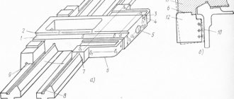
Bed, racks, lead screw, drive shaft and fast movement drive of the caliper
The tension of the drive belt for fast movements of the caliper is carried out by adjusting screw 3, which is locked with nut 2.
When cleaning the lead screw 13 and the drive shaft 14, it is necessary to remove the shields 9 and 10. To do this, you need to loosen the screws 19 and remove the shields from the side of the rear bracket 18.
Technical characteristics of the lathe 16K20
| Parameter name | 16K20 | 16K20P |
| Basic machine parameters | ||
| Accuracy class according to GOST 8-82 | N | P |
| The largest diameter of the workpiece installed above the bed, mm | 400 | 400 |
| Height of the center axis above the flat guides of the frame, mm | 215 | 215 |
| The largest diameter of the workpiece processed above the support, mm | 220 | 220 |
| Maximum length of the workpiece installed in the centers (RMC), mm | 710, 1000, 1400, 2000 | 710, 1000 |
| The greatest distance from the axis of the centers to the edge of the tool holder, mm | 225 | 225 |
| The largest diameter of the drill when drilling steel parts, mm | 25 | 25 |
| Maximum mass of workpiece processed in centers, kg | 460..1300 | 460..1300 |
| Maximum mass of workpiece processed in the chuck, kg | 200 | 200 |
| Spindle | ||
| Spindle hole diameter, mm | 52 | 52 |
| The largest diameter of the rod passing through the hole in the spindle, mm | 50 | 50 |
| Spindle rotation speed in forward direction, rpm | 12,5..1600 | 12,5..1600 |
| Spindle rotation speed in reverse direction, rpm | 19..1900 | 19..1900 |
| Number of forward spindle speeds | 22 | 22 |
| Number of spindle reverse speeds | 11 | 11 |
| Spindle end according to GOST 12593-72 | 6K | 6K |
| Tapered spindle bore according to GOST 2847-67 | Morse 6 | Morse 6 |
| Spindle flange diameter, mm | 170 | 170 |
| Maximum torque on the spindle, Nm | 1000 | 1000 |
| Caliper. Submissions | ||
| Maximum length of longitudinal movement, mm | 645, 935, 1335, 1935 | 645, 935 |
| Maximum length of transverse movement, mm | 300 | 300 |
| Speed of fast longitudinal movements, mm/min | 3800 | 3800 |
| Speed of fast transverse movements, mm/min | 1900 | 1900 |
| Maximum permissible speed of movement when working on stops, mm/min | 250 | 250 |
| Minimum permissible speed of movement of the carriage (support), mm/min | 10 | 10 |
| Price for dividing the longitudinal movement dial, mm | 1 | 1 |
| Transverse movement dial division price, mm | 0,05 | 0,05 |
| Longitudinal feed range, mm/rev | 0,05..2,8 | 0,05..2,8 |
| Transverse feed range, mm/rev | 0,025..1,4 | 0,025..1,4 |
| Number of longitudinal feeds | 42 | 42 |
| Number of cross feeds | 42 | 42 |
| Number of threads to be cut - metric | ||
| Number of threads to be cut - modular | ||
| Number of threads cut - inch | ||
| Number of threads to be cut - pitch | ||
| Limits of metric thread pitches, mm | 0,5..112 | 0,5..112 |
| Limits of pitches of inch threads, threads/inch | 56..0,5 | 56..0,5 |
| Limits of modular thread pitches, module | 0,5..112 | 0,5..112 |
| Limits of pitch thread pitches, diametric pitch | 56..0,5 | 56..0,5 |
| The greatest force allowed by the feed mechanism on the cutter is longitudinal, N | 5884 | 5884 |
| The greatest force allowed by the feed mechanism on the cutter is transverse, N | 3530 | 3530 |
| Cutting slide | ||
| Maximum movement of the cutting slide, mm | 150 | 150 |
| Movement of the cutting slide by one division of the dial, mm | 0,05 | 0,05 |
| Maximum angle of rotation of the cutting slide, degrees | ±90° | ±90° |
| Scale division of the tool slide rotation scale, deg | 1° | 1° |
| The largest cross-section of the cutter holder, mm | 25 × 25 | 25 × 25 |
| Height from the supporting surface of the cutter to the axis of the centers (cutter height), mm | 25 | 25 |
| Number of cutters in the cutting head | 4 | 4 |
| Tailstock | ||
| Tailstock quill diameter, mm | ||
| Cone of the hole in the tailstock quill according to GOST 2847-67 | Morse 5 | Morse 5 |
| Maximum movement of the quill, mm | 150 | 150 |
| Movement of the quill by one division of the dial, mm | 0,1 | 0,1 |
| The amount of lateral displacement of the headstock body, mm | ±15 | ±15 |
| Electrical equipment | ||
| Main drive electric motor, kW | 11 | 11 |
| Electric motor for fast movement drive, kW | 0,12 | 0,12 |
| Coolant pump electric motor, kW | 0,125 | 0,125 |
| Dimensions and weight of the machine | ||
| Machine dimensions (length width height) RMC=1000, mm | 2795 × 1190 × 1500 | 2795 × 1190 × 1500 |
| Machine weight, kg | 3010 | 3010 |
Technical capabilities and characteristics of 16K20
Screw-cutting lathes 16K20 (as well as their analogues) are distinguished by the following characteristics.
- The spindle can rotate in the frequency range of 12.5–1600 rpm.
- It is allowed to process parts whose maximum cross-section is 310 mm above the recess, 400 mm above the bed and 220 mm above the support.
- Rapid movements in the transverse direction can be made at a speed of 1.9 m/min, longitudinal movements - 3.8 m/min.
- The technical capabilities of the 16K20 screw-cutting lathe allow it to produce threads with various parameters. Their pitch can be in the range: 0.5–56 (modular and pitch), 0.5–112 threads per inch (inch), 0.5–112 mm for metric.
- The length of the workpiece can be up to 2000 mm.
- The number of longitudinal and transverse feeds is 22 and 24, respectively. The range of longitudinal feeds is 0.05–2.8 mm/rev, transverse feeds are 0.025–1.4 mm/rev.
- The characteristics of the 16K20 machine allow processing workpieces weighing up to 1300 kg.
- To rotate the spindle, you can select one of 22 speeds (direct).
- The hole in the spindle has a diameter of 52 mm.
The kinematic diagram of the machine can be found in the photo below:
Kinematic diagram of the 16K20 machine (click to enlarge)
Depending on the length indicated in the equipment passport, the weight of the 16K20 machine can be:
- 3685 kg (for model with a length of 3795 mm);
- 3225 kg (3195 mm);
- 3005 kg (2795 mm);
- 2835 kg (2505 mm).
The engine power of the hydraulic station and the main drive of the 16K20 machine (according to the passport and actual) is 11 kW. Accordingly, this indicator is taken as the power of this model.
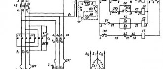
Controls of the machine 16K20
To start the 16K20 screw-cutting lathe, the operator needs to press a button, which closes the electrical circuit in the contactor coil. In addition to the main button, the machine has a number of elements through which the following equipment options are controlled:
- moving the equipment support and carriage at high speeds (this option is controlled using the so-called jog button);
- stopping the rotation of the equipment motor;
- starting and stopping the coolant pump.
The electrical circuit of the 16K20 screw-cutting lathe also contains a special relay, which serves to limit the idle speed of the engine. The diagram itself can be found below:
Circuit diagram of a 16K20 lathe (click to enlarge)
The handles located on the machine body are used to solve such problems as:
- selection of the type of work to be performed: type of thread to be cut and feed characteristics;
- quill fixation;
- friction clutch control;
- movement of the carriage and longitudinal movement of the slide;
- setting the thread pitch and feed value for its execution;
- disabling the feed box - for those cases when the thread is cut directly;
- selection of spindle rotation mode – number of revolutions;
- turning the lead screw nut on and off;
- start button of the input circuit breaker;
- choice of thread cutting direction;
- selecting a mode for cutting threads with normal or increased pitch.
On 16K20 machines, a steady rest can be used, which is designed to prevent the workpiece from bending during work, and also helps to fix it, thereby increasing the accuracy of processing. The lunette looks like this:
Steady rest for screw-cutting lathe 16K20