16K20 - basic machine of normal accuracy;
It should be remembered that in the process of technical improvement of 16K20 lathes, some changes may be made to their design. Therefore, when ordering spare parts, the following information must be provided:
- The model and serial number of the machine are indicated on the plate placed on the spindle head;
- It is advisable to purchase components (bearings, electrical equipment, etc.) according to the type or number printed directly on them indicating the basic data.
- If this is not possible, the type or number can be determined using the diagrams and tables in the manual.
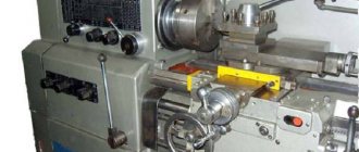
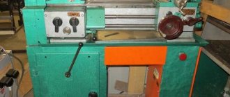
Controls of the machine 16K20
Controls of the machine 16K20.
- Feed rate table
- Thread type selection knob
- Spindle speed selection knob
- Emergency stop button
- Main motor start button
- Chuck protective screen
- Three jaw chuck
- Feed speed selector knob
- Feed box oil indicator
- 4-position tool holder
- Lamp
- Flywheel for moving the upper carriage
- Tailstock
- Tailstock quill feed flywheel
- Emergency stop pedal
- Longitudinal caliper feed flywheel
- Toolholder cross feed mechanism
- Caliper apron
- Longitudinal and cross feed handle with quick feed button
- Spindle rotation switch.
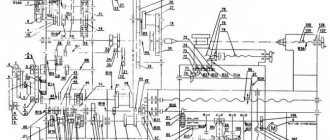
Kinematic diagram of a lathe with OSU 16K20T1
Kinematic diagram of the lathe 16K20T1
Kinematic diagram of the lathe 16K20T1
On machines of version 16K20T1.01, a spindle head is installed, which has 3 speed ranges that can be switched manually. The main movement drive includes a motor unit with an asynchronous electric motor, an automatic 9-speed gearbox AKS-309-16-51 and a spindle head, connected by wedge or polyclick belt drives.
From the Ml engine, through a poly-V belt drive (with pulleys with a diameter of 105 and 264 mm), rotation is transmitted to shaft I of the spindle headstock, and then through gears 1 and 2 to shaft II. Next, three spindle speed ranges are provided (22.4–315; 63–900; 160–2240 rpm). Within each range, the speed is infinitely adjustable by changing the speed of the ML electric motor
To obtain the first range of rotation frequencies, movement from shaft II (through gears 4 and 3) is transmitted to shaft III, then (through gears 7 and - to shaft IV and further (through gears 9 and 11) - to shaft V (spindle ).
To obtain the second range, wheel 11 is engaged with wheel 6, and wheel 3 is disengaged with wheel 4.
To obtain the third range, wheel 10 is engaged with wheel 5, and wheel 3 (as in the previous case) is disengaged with wheel 4. Gears 12 and 13 are used to rotate the BE-178 thread-cutting sensor.
Gear 12 is split and serves to select a gap in the meshing in order to prevent mismatch between the position of the spindle and the sensor.
An M2 electric motor (adjustable high-torque DC or frequency-controlled asynchronous) is used to drive the support feed along the X-axis (transverse movement). From the M2 motor, rotation (through gears 14 and 15) is transmitted to a ball screw (step P = 5); reverse communication along the path is carried out by a photopulse sensor BE-178.Chain for driving the caliper feeds along the Z axis (longitudinal movement): M3 engine - gears 16, 17 - ball screw (P = 10) - BE-178 sensor.
The rotation chain of the six-position turret: asynchronous electric motor M4 - gears 18 and 19 - worm 20 - worm gear 21. The asynchronous motor M5 rotates the gear pump VG11-11A, which provides centralized lubrication of the machine.
Installing and removing the machine chuck 16K20:
- When installing and removing the chuck, protect the guides and bed with wooden boards placed under the chuck. Hold the chuck while you loosen the 3 cam locks by rotating ¼ turn counterclockwise. Align the A marks with each other. Carefully remove the cartridge.
- Before starting installation, you should make sure that there are no nicks on the mating surfaces and thoroughly wipe them with a lint-free cloth. Install the chuck onto the front end of the spindle. Clamp the cam lock of the clamping eccentric by rotating clockwise. The clamping eccentric mark A (Fig. 5) must be located between the 2 marks B (Fig. 5). The accuracy of the chuck fit on the spindle is checked by an indicator using a control band located on the outer cylindrical surface of the chuck body. Radial runout should not exceed 0.02 mm. Fig.5 Installing and removing the machine chuck 16K20.
- The fixed steady rest serves primarily to support long workpieces and ensures their reliable processing without vibrations; it is mounted on the frame using a fastening strip. *
- Install the steady rest crackers so that there is no gap between them and the workpiece and they do not pinch it. During processing of the part, it is necessary to lubricate the crackers well.
- The movable steady rest is installed on the longitudinal slide of the support and thus repeats the movement of the turning cutter. It prevents elastic deformation of long and thin workpieces under the pressure of a turning tool. When machining a workpiece, it is necessary to install the crackers in the same way as on a stationary rest.
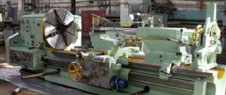
Purpose of the machine
In the early 70s, Soviet Mash, after several modifications of the DIP models, launched the production of turning screw-cutting 16k20. Which in 1972 received a gold medal at the international fair in Leipzig.
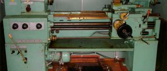
Intended for a variety of turning operations, it made it possible to turn various simple and complex surfaces in the chuck, on the faceplate and in centers. And besides, boring, facing, cutting, and cutting all kinds of threads. Its design was so successful that in the USSR it was long considered the best equipment of its type. Screw-cutting machines differ from other representatives of the turning group in their greater versatility.
Therefore, their use is more rational in small-scale or piece production.
Unpacking and transporting the 16K20 lathe
Fig. 1. Transportation diagram of the 16K20 lathe.
The lathe 16K20 is supplied on a pallet. When unpacking, care must be taken not to damage the machine with the unpacking tool. If upon unpacking you discover any damage that occurred during transportation, please notify the seller immediately. Do not operate the machine in this case.
Packing lists for accessories and tools are located in a separate box placed on the machine pallet.
Before transporting the 16K20 lathe unpacked, you must make sure that the moving components are securely fastened to the bed. The tailstock is fixed in the right extreme position, and the carriage is fixed in the middle part of the bed between the rope slings.
Transportation of the machine is carried out according to the transportation scheme (Fig. 1) using a four-line rope, ends 1 and 2 of which are put on two 60 mm steel rods. 3 (Fig. 1), inserted into specially provided holes in the base of the machine.
In places where the rope touches the machine, you need to install wooden spacers 4 (Fig. 1). When transporting to the installation site and when lowering it onto the foundation, it is necessary to ensure that the machine is not subjected to strong shocks and shocks.
Information about the manufacturer of the lathe 16K20t1
Manufacturer of the 16K20t1 lathe - Moscow Machine Tool Plant named after. A.I. Efremova , founded in 1857.
The first universal screw-cutting lathes with a gearbox for the first time in the USSR began to be produced at the Moscow Machine Tool Building named after. A.I. Efremov in 1932 and received the names DIP-200, DIP-300, DIP-400, DIP-500 ( DIP
- Catch up and Overtake), where 200, 300, 400, 500 is the height of the centers above the frame.
As the design of the machines improved, the plant produced more and more modern models - 1A62, 1K62, 16K20, MK6056.
Machine tools produced by the Moscow Machine Tool Plant Krasny Proletary
- 1A62
- universal screw-cutting lathe, Ø 400 - 1K62
- universal screw-cutting lathe, Ø 400 - 1K62B
– high-precision universal screw-cutting lathe, Ø 400 - 1K282
- eight-spindle vertical lathe, Ø 250 - 1K620
- universal screw-cutting lathe with variator, Ø 400 - 1K625
- lightweight screw-cutting lathe with an increased line of centers, Ø 500 - 16A20F3
– CNC lathe, Ø 400 - 16B20P
- high-precision screw-cutting lathe, Ø 400 - 16K20
– universal screw-cutting lathe Ø 400 - 16K20VF1
- universal high-precision screw-cutting lathe with digital display, Ø 400 - 16K20M
- mechanized screw-cutting lathe, Ø 400 - 16K20P
- high-precision screw-cutting lathe, Ø 400 - 16K20PF1
- high-precision screw-cutting lathe with digital display, Ø 400 - 16K20F3
- CNC lathe, Ø 400 - 16K20F3S32
- CNC lathe, Ø 400 - 16K20T1
- lathe with operational control, Ø 500 - 16K25
- lightweight screw-cutting lathe with an increased line of centers, Ø 500 - 162
— universal screw-cutting lathe, Ø 420 - 1622
— universal screw-cutting lathe, Ø 120 - 1730
— semi-automatic multi-cutting lathe, Ø 410 - DIP-40 (1D64)
- universal screw-cutting lathe, Ø 800 - DIP-50 (1D65)
- universal screw-cutting lathe, Ø 1000 - DIP-200
– universal screw-cutting lathe, Ø 400 - DIP-300
– universal screw-cutting lathe, Ø 630 - DIP-400
– universal screw-cutting lathe, Ø 800 - DIP-500
– universal screw-cutting lathe, Ø 1000 - MK6046, MK6047, MK6048
- universal screw-cutting lathe, Ø 500 - MK6056, MK6057, MK6058
- universal screw-cutting lathe, Ø 500 - MK-3002
- table lathe, Ø 220
Installation of machine 16K20
The longevity of maintaining the accuracy of the machine largely depends on the correct installation. The machine should be installed on the foundation according to the installation drawing (Fig. 2).
Rice. 2 Installation drawing of the foundation of the lathe 16K20
The depth of the foundation is taken depending on the soil, but must be at least 150 mm.
If the 16K20 machine is intended for finishing operations, the foundation depth must be at least 500 mm.
The machine is attached to the foundation with four foundation bolts with M24 threads.
When installing a 6K20 lathe, it is necessary to provide for the presence of free zones for opening the door of the electrical equipment cabinet and turning the sub-motor plate of the main drive electric motor, as well as for the possibility of dismantling the shields of the drive shaft and lead screw for cleaning and lubrication of the latter.
As an option, it may be proposed to install the machine at an angle of 10° to the wall of the workshop or equipment placement line.
Preparing the 16K20 machine for launch.
Alignment of the installation of the machine in a horizontal plane is carried out using a level installed in the middle part of the support parallel and perpendicular to the axis of the centers (the foundation bolts must not be tightened). In any position of the carriage, the level deviation should not exceed 0.04 mm per 1000 mm.
Having familiarized yourself with the instructions set out in the sections immediately following this, you can, in accordance with the sequence recommended below, begin preparing the 16K20 lathe for start-up.
Perform all operations related to preparing the 16K20 machine for startup, set out in section 6 “Lubricating the machine,” and fill the base chip collector located under the bed with coolant.
Connect according to the instructions in Section 7 “Electrical Equipment”. the machine to the grounding circuit and, after checking the correspondence of the network voltage and the electrical equipment of the machine, connect it to the electrical network.
After familiarizing yourself with the purpose of the controls (section, check by hand the operation of all machine mechanisms. The spindle rotation switch lever must be set to the neutral position.
You should be aware that due to the presence of locking devices, the 16K20 machine cannot be turned on:
- with the control cabinet door open;
- with the cover of replaceable gears open;
- with the cartridge guard cover folded back.
A description of blocking devices is placed in section 7 “Electrical equipment”.
By pressing the black “Start” button 5 (Fig. 4), turn on the main drive electric motor.
ATTENTION! It is imperative to check the operation of the centralized lubrication system of the spindle head of the 16K20 machine and the feed box using the oil indicator. If the oil indicator does not rotate, operation of the machine is unacceptable .
The operation of the lubrication pump can be monitored through a peephole located on the front of the headstock.
Using a switch, check the operation of the coolant pump motor.
After completing these operations, the machine is ready to start.
Specifications
- Accuracy group – N.
- Center height (mm) – 215.
- Ø standard cartridge – 200 or 250 mm.
- The speed range of rotation of the spindle shaft in the direct direction (rpm) is 12.5–1.6*103. Adjustment discrete number of gears 24.
Moreover, both in the forward and reverse directions there are 2 gears with a frequency of 500 and 630 rpm. Therefore, some sources talk about 22 forward and 11 reverse transmissions.
- The speed range of rotation of the spindle shaft in the reverse direction (rpm) is 19–1.9*103. Adjustment discrete number of gears 12.
- Feed range (mm/rev): along the axis – 0.05–2.8; across 0.025–1.4.
- The pitch range of metric threads is 0.5–112 mm.
- The range of modular thread pitches is 0.5–112 modules.
- The range of inch thread pitches is 56–0.5 threads/inch.
- The range of pitch thread pitches is 56–0.5 pitches.
Limit parameters
- The maximum permissible diameter of a “disc” workpiece turned over the bed is 400 mm.
- The maximum diameter of the “shaft” type workpiece turned over the caliper is 220 mm.
- Limit length of the workpiece to be turned (mm) – 710, 1000, 1400, 2000.
- Limit length of turning (mm) – 645.935, 1335, 1935.
- The Ø of the “rod” type workpiece is no more than 50 mm.
- The weight of the workpiece fixed for processing in centers (no more) is 460, 650, 900, 1300 kg.
- The weight of the blank fixed for processing in the chuck (no more) is 200 kg.
- The force developed by the feed unit at the stop (no more) is 800 kgf along the axis, 460 kgf across it.
- The force developed by the feed unit on the cutter (no more) is 600 kgf along the axis, 360 kgf across it.
Machine lubrication 16K20.
Correct and regular lubrication of the 16K20 lathe is of great importance for its normal operation and durability. Therefore, you must strictly adhere to the recommendations below.
When preparing the machine for startup, it is necessary to wash the filter mesh in kerosene, then, in accordance with the “Lubrication Card” and the lubrication diagram (Fig. 3), fill the reservoirs with lubricant and lubricate the mechanisms indicated in the card.
Lubrication should be carried out with lubricants specified in the lubrication chart, or their substitutes given in the “List of recommended lubricants” (clause 6.3).
Repair of screw-cutting lathe 16K20P
Below are links to three albums dedicated to the repair of a 16K20P screw-cutting lathe. This documentation was developed by the State Design and Technological Institute for Modernization and Automation, Repair of Metal-Cutting Machine Tools and Maintenance of Metalworking Equipment with Software Control - GPKTI STANCOSERVICE.
Contents “Repair of screw-cutting lathe 16K20P. Album 1. General description"
- General description of the machine
- Purpose and brief technical characteristics
- Controls
- Specification of main components
- Basic parameters of gears, worms, screws, nuts, racks
- Kinematic diagram
- Specification of rolling bearings
- Machine lubrication
- Lubrication map
- Description of the electrical circuit
- Electrical circuit diagram
- Machine electrical equipment specification
- Drawings of machine components
- Bed 16K20.010.001; 16K20.011.001; 16K20.012.001; 16K20.016.001
- Spindle head 16K20.020.001
- Tailstock 16B20.030.001; 16B20P.030.001
- Four-position tool holder 16K20.041.001
- Carriage and support 16K20.040.001 and 16K20.050.001
- Apron 16B20P.061.000
- Feed box 16B20P.070.000
- Gearbox 16K20.080.001
Download for free “Repair of screw-cutting lathe 16K20P. Album 1. General description" in normal quality (70 pages) can be found at the link below:
Contents “Repair of screw-cutting lathe 16K20P. Album 2. Technological process of major repairs"
- Route of a 16K20P screw-cutting lathe during a major overhaul
- List of equipment used during major repairs of the machine
- Route technological process of disassembling the machine into units
- Recommendations for defect detection and restoration of parts
- Route technological processes for parts repair
- Requirements for the quality of machine assembly
- Route technological process for assembling machine components
- Route technological process of assembly and debugging of the machine
- Testing the machine after a major overhaul
- Protocol for checking the machine for rigidity and accuracy according to GOST 18097-72
- Noise Level Standards and Test Methods
- Applications
Download for free “Repair of screw-cutting lathe 16K20P. Album 2. Technological process of major repairs" in good quality (100 pages) can be found at the link below:
Contents “Repair of screw-cutting lathe 16K20P. Album 3. Replaceable parts"
- Temporary norms for the consumption of replaceable parts when repairing a 16K20P machine
- Working drawings of replacement parts
Download for free “Repair of screw-cutting lathe 16K20P. Album 3. Replaceable parts" in good quality (196 pages) can be found at the link below:
Machine lubrication map 16K20
| Headstock | Auto | I-20A GOST 20799-75 | Annually (approximately 700 operating hours) | Fill—1; drain—2 |
| Gearbox | Auto | I-20A GOST 20799-75 | Annually (approximately 700 operating hours) | Fill—3; drain—4 |
| Caliper apron | Auto | I-30A GOST 20799-75 | Annually (approximately 700 operating hours) | Fill—5; drain—6 |
| Bed guides | Auto, using apron lubrication system | I-30A GOST 20799-75 | 11 | |
| Cross slide, top slide | Manual | I-30A GOST 20799-75 | Weekly | 8,10 |
| Tailstock | Manual | I-30A GOST 20799-75 | Weekly | 9 |
| Replacement gears | Manual | CIATIM-203 GOST 8773-73 | Daily | 12 |
| Tool holder | Manual | I-30 AGOST 20799-75 | 1 time per shift | 7 |
List of lubricants recommended for lubrication of the 16K20 machine
| I-20A GOST 20799-75 | I-30A GOST 20799—75 | CIATIM-203 GOST 8773-73 |
| Viscosity at 50°C 17—23 cSt | Viscosity at 50°C 27—33 cSt | Effective viscosity at -30°C — no more than 1000 Pz |
| Flash point (in open crucible) — not lower than 165°С | Flash point (in open crucible) — not lower than 180°С | Corrosion test - withstands |
| Pour point - 30°C | Pour point - 15°C | Content of free alkalis in terms of 0.1% |
| Acid number - no more than 0.14 mg KOH/1 g oil | Acid number - no more than 0.2 mg KOH/1 g oil | |
| Ash content — no more than 0.007% Content of mechanical impurities - absent | Ash content - no more than 0.007% Content of mechanical impurities - absent | Free organic acid content - none Water content - no more than 2.5% |
| Content of water-soluble acids and alkalis - none | Content of water-soluble acids and alkalis - none | The content of mechanical impurities is no more than 0.25% |
| Water content - none | Water content - none | |
| Replacement with IGP-18 TU38-1-273—69 is allowed | Replacement with IGP-30 TU38-1-273—69 is allowed |
In the absence of lubricants specified in the list, it is permissible to use only those oils whose main characteristics correspond to those given.
Description of the lubrication system of the 16K20 machine
The 16K20 machine uses an automatic centralized lubrication system for the spindle head and feed box.
The pump, driven from the main drive electric motor through a belt drive, sucks oil from the oil bath and delivers it through a strainer to the spindle bearings and oil distribution trays. About a minute after turning on the electric motor, the oil indicator disk on the spindle head begins to rotate. Its constant rotation indicates normal operation of the lubrication system.
During operation, it is necessary to monitor the rotation of the oil indicator disk on the spindle head of the 6K20 machine. When it stops, you must immediately turn off the machine and check the filter. Remove the filter mesh elements in the plastic frame. Rinse each element in kerosene until completely clean. Do not blow out the filter elements with compressed air, as this may damage the fine mesh. After cleaning, assemble and install the filter.
ATTENTION! Filters must be cleaned before and after each oil change. In a new machine, it is advisable to clean the strainer at least twice a week for the first two weeks, and then once a month.
Every day before starting work, you need to check the oil level in the tank using the indicator and, if necessary, add it through the hole in the filler filter. When changing the oil, the reservoir is drained through a plug. Before filling the tank with oil, it must be cleaned and rinsed with kerosene.
The apron mechanism is automatically lubricated by an individual plunger pump. Oil is poured into the housing through hole 5 (Fig. 3), closed with a plug, and drained through hole 6 (Fig. 3). The oil level is controlled by the oil indicator on the front side of the apron.
The frame guides are lubricated using a centralized lubrication system of the caliper apron (repeatedly, depending on the intensity of use).
The guides of the transverse carriage, the upper carriage, as well as their lead screws must be lubricated using an oil can.
The carriage guides and cross slides are lubricated at the beginning and middle of the shift until an oil film appears on the guides.
Every day at the end of the shift, you need to remove the cutting head from the 16K20 lathe, clean its working surfaces and lubricate the conical axis of the tool holder.
Replacement gears and the axis of the intermediate replacement gear 12 (Fig. 3) are lubricated manually with CIATIM-203 GOST 8773-73 grease.
The support bushings of the replacement gears are lubricated using an oil can.
The remaining points are lubricated manually using the oil can supplied with the machine.
ATTENTION! The first oil change should be made a month after putting the 16K20 machine into operation, the second - after three months, and then strictly following the instructions of the lubrication chart.
Prevention and repair
Daily care activities
Before starting work:
- Inspection of the machine.
- Lubricate the lead screw and shaft.
- Controlling the amount of oil.
- Switching on with checking nodes without load.
During operation:
- Switch feeds and gears only after the moving units have finally stopped.
- When working with cast iron or abrasive materials, cover the guides with thick cloth.
After the end of working hours: turn off the power supply, remove the shavings, wipe with a rag soaked in kerosene, and lubricate the open guides with oil.
Malfunctions and their elimination
| Symptoms | Cause | Correction method |
| Ovality of the part or hole being bored. | Blank runout in the cartridge. | Boring of jaws. |
| Quill play or weak fastening of the thrust headstock. | Adjusting or repairing the quill. | |
| Hole axis offset. | Misalignment of spindle shaft and tailstock. | Adjustment. Or repair with adjustment. |
| Significant cone of cylindrical parts. | Mismatch between the centers of the spindle shaft and the thrust head. | Adjustment. |
| Worn caliper or bed guides | Adjustment or repair. | |
| Dimensional instability during trimming. | Axial play of the spindle shaft. | Replacing rotation bearings. |
A slight increase in caliper clearances can be eliminated by adjusting the wedges in the transverse or upper slide guides, and the adjustment screws in the rear guide of the longitudinal slide. Then, moving the slide to the maximum distance, make sure that it moves smoothly. Leaks in the screw drive of the cross slide are eliminated by adjusting the screws located behind the tool holder platform.
Electrical equipment of the machine 16K20
To ensure high reliability in operation and maintenance of the electrical equipment of the 16K20 machine by semi-skilled specialists, all relay-contactor equipment and other electrical equipment have a simple design and have been tested over many years of operation in various conditions.
The electrical equipment of the 16K20 machine (with the exception of several devices) is mounted in a control cabinet located on the rear side of the machine.
The electrical equipment of the 16K20 machine is designed for connection to a three-phase alternating current network with a solidly grounded or insulated neutral wire.
The electrical connection and the power cables used must comply with regulations. The voltage and frequency in the electrical network must correspond to the data on the machine nameplate. The fuse should be 25A.
Use connecting cables only with the designation H07RN-F.
Electrical connections and repairs must be carried out by qualified electricians.
The electrical connection is made to the terminal blocks in the electrical cabinet at the rear of the machine.
Safety instructions
The 16K20 machine must be securely connected to the workshop grounding device (circuit).
The electrical resistance measured between the ground screw and any metal part of the machine that may become live as a result of insulation breakdown should not exceed 0.1 ohm.
IT IS STRICTLY PROHIBITED to work with an open terminal box and control cabinet!
A safety light-signal device is installed in the control cabinet, indicating the presence of voltage between the output terminals of the input circuit breaker and the neutral wire.
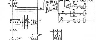
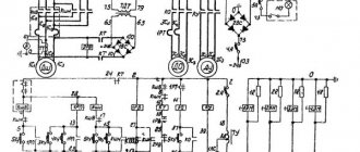
Electrical circuit diagram
There are 3 operating voltages in electrical equipment:
- Motor power supply –380V.
- Automatic - 110V.
- Workplace lighting – 24V.
List of machine electrical components:
- R – Load indicator E38022 (ammeter ~20A).
- F1 – Current protection circuit breaker AE-20-43-12.
- F2 – Automatic AE-20-33-10.
- F3, F4 – E2782—6/380 – fuse link.
- F5 – TRN-40 – electrothermal protection.
- F6, F7 – TRN-10 – electrothermal protection.
- N1 – safety light-signal device UPS-3.
- N2 – NKSO1X100/P00-09 – electric lamp with S24-25 lamp.
- N3 – KM24-90 – switching lamp.
- K1 – PAE-312 – remote magnetic starter.
- K2 – PME-012 – remote starter.
- KZ – RVP72-3121-00U4 – time delay relay (Limit of operation of the main motion electric motor without load).
- K4 – RPK-1-111 – engine starter.
- M1 – Main motion electric motor 4A132 M4, rated power 11 kW.
- M2 – 4А71В4 – electric motor (accelerated displacement of the caliper).
- M3 – Electric pump PA-22 (emulsion supply).
- M4 – 4A80A4UZ – asynchronous electric motor.
- S1 – VPK-4240 – limit switch (Distribution device door).
- S2 – PE-041 – rotary control switch (unlocking S1).
- S3 and S4 – PKE-622-2 – push-button control unit.
- S5 – MP-1203 – microswitch.
- S6 – VPK-2111 – push-type limit switch.
- S7 – PE-011 – rotary control switch.
- S8 – VPK-2010 push-type limit switch.
- T – TBSZ-0.16 – step-down transformer.
Diagram of lathe controls
Locking devices for electrical equipment of machine 16K20
The electrical circuit includes a lock that turns off the input circuit breaker when the control cabinet door is opened.
When the input circuit breaker is turned on, opening the cabinet door triggers the limit switch, which disconnects the electrical equipment of the machine from the network.
When the housing of the replacement gears is opened, a microswitch is activated, turning off the main drive motor.
The limit switch is mounted in the control cabinet, the microswitch is on the feed box housing.
For inspection and adjustment of electrical equipment under voltage (with the cabinet door open), the circuit provides a release switch installed in the control cabinet. This switch should only be used by qualified electricians.
Instructions for the initial start-up of the 16K20 machine
During the initial start-up of the 16K20 machine, it is necessary to check the reliability of grounding and the quality of installation of electrical equipment by external inspection. After inspection, disconnect the power wires of all electric motors at the terminal sets in the control cabinet and connect the machine to the workshop network using the input circuit breaker. Check the operation of all locking devices
- Using manual controls, check the precise operation of magnetic starters and relays.
- Once smooth operation of all electrical devices located in the control cabinet is achieved, connect the previously disconnected wires to the terminal sets.
- By alternately turning on the electric motors of the main drive and quickly moving the caliper, check the correct direction of their rotation.
- After making sure that the electric motors rotate correctly, you can begin testing the machine in operation.
Recommendations for servicing the electrical equipment of the 16K20 machine.
It is necessary to periodically check the condition of the starting and relay equipment of the 16K20 machine. All parts of electrical devices must be cleaned of dust and dirt. If carbon deposits form on the contacts, the latter must be removed using a velvet file or glass paper. To avoid rust, the interface between the core and the starter armature must be periodically lubricated with machine oil, followed by obligatory wiping with a dry cloth (to prevent the armature from sticking to the core). When inspecting relay equipment, special attention should be paid to the reliability of the closing and opening of contact bridges.
- The frequency of technical inspections of electric motors is set depending on production conditions, but not less than once every two months.
- During technical inspections, the condition of the input wires of the stator winding is checked, the motors are cleaned of contamination, and the reliability of grounding and connection of the shaft to the drive mechanism is monitored.
- The frequency of preventative repairs is set depending on production conditions, but at least once a year.
- During preventive maintenance, electric motors must be disassembled, internal and external surfaces must be cleaned, and bearing grease must be replaced.
- Under normal operating conditions, bearing grease should be replaced after 4000 hours of operation, and when operating the electric motor in dusty and humid environments - as necessary.
- Before filling with fresh grease, the bearings must be thoroughly washed with gasoline. Fill the chamber with lubricant to 2/3 of its volume. Recommended lubricants are given in table. 5.
- Preventive inspection of circuit breakers must be carried out at least once every six months, as well as after each shutdown due to a short circuit, including repeated ones.
- During inspection, you need to clean the switch from soot and metal deposits, check the tightness of the screws, the integrity of the springs and the condition of the contacts. The hinges of the switch mechanism should be periodically (after approximately 2,000-3,000 starts) lubricated with instrument oil.
ATTENTION! Do not make any adjustments to the switches under operating conditions. It was made by the manufacturer!