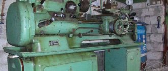
Metal cutting is used not only in industrial enterprises, but also in private workshops. Metalworking lathes are used for cutting. One of them, the universal screw-cutting lathe 1616, began to be produced in serial form starting in 1949 at the SVSZ plant (Middle Volga Machine Tool Plant).
History of creation
This is an example of successful and reliable equipment for special metal processing, which is in demand not only in our country, but also abroad. This universal machine replaced model 1615 in production. It was produced in two versions:
- Normal accuracy (directly 1616).
- Increased accuracy - 1616 P.
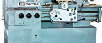
Subsequently, the model was improved to the 16B16 series. Since the 90s, the plant has been producing SAMAT turning equipment based on the 1616 model. Now the 1616 lathe has been discontinued, and more modern models are being produced. But modification 1616 is still used in many enterprises and private businesses.
Electrical circuit diagram of a 1A616 screw-cutting lathe.
The electrical circuit diagram of the universal screw-cutting lathe 1A616 is shown in the following figure:
You can download for free the electrical circuit diagram of the 1A616 screw-cutting lathe with specifications and in excellent quality from the link below:
the 1A616 screw-cutting lathe is shown in the following figure:
You can download this version of the electrical circuit diagram of the 1A616 screw-cutting lathe for free with specifications and in excellent quality from the link below:
Detailed description of the case
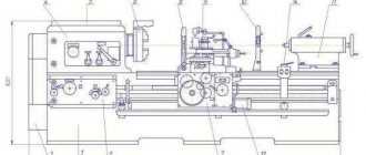
Main components of lathe 1616:
- Cast iron bed with diagonal stiffeners and two guides. The front, reinforced guide is designed to move the caliper, the rear - to move the tailstock. The frame is bolted to cast iron pedestals.
- Gearbox (front spindle headstock with pitch increasing unit and overhaul device).
- Tailstock with a movable quill and position securing handle.
- A feed box that ensures the movement of the cutter on the support relative to the rotating workpiece.
- Closed apron with torque transmission gear block.
- A movable support for moving the cutter along, across and at an angle to the spindle axis.
- Steady rests are special devices to facilitate the turner’s work with long workpieces and increase the accuracy of part processing.
- Electrical cabinet.
- Two three-phase electric motors at 380 Volts.
- Electric pump to supply coolant (power 4.0 kW, 1430 rpm, 220/380 V).
- Lighting lamp 36 V.
- Two support stands (rear and front).
- A cooling system that increases the strength characteristics of the cutting tool and the quality of the machined surface.
- Gearbox enclosed in a cast iron housing with a hermetically sealed lid. Installed on the left side of the frame and secured with bolts.
The package includes a tray located between the frame and the cabinets (to collect chips and liquid coming from the cooling circuit).
Workspace dimensions
Location of controls
The 1616 lathe controls include:
- Handles.
- Flywheels.
- Caliper
- Tailstock fastening nut, screw for its transverse movement.
- Three-phase asynchronous electric motor.
Functions of handles and handwheels as controls:
- Turning friction clutches on and off.
- Regulating the spindle speed, setting its speed, multiple multipliers for each mode.
- Changing the direction of the working feed.
- Adjustment of thread characteristics (speed, feed rate and pitch).
- Changing the direction of feeds.
- Enable and disable search.
- Turning on the lead screw.
- Starting the transverse and longitudinal feed of the caliper.
- Securing the tailstock quill.
- Starting the machine by reversing the spindle.
Technical characteristics of screw-cutting lathe 1A616.
| Quantities | ||
| The largest diameter of the processed bar | mm | 34 |
| The largest diameter of the product installed above the caliper | mm | 180 |
| The largest diameter of the product installed above the bed | mm | 320 |
| Maximum turning length | mm | 660 |
| Pitch of cut metric thread | mm | 0,5-24 |
| Pitch of cut inch thread | threads per inch | 56-1 |
| Pitch of cut modular thread | modules | 0,25-22 |
| Pitch of cut pitch thread | pitches | 128-2 |
| Spindle speed limits | rpm | 9-1800 |
| Spindle inner taper | Morse No. 5 | |
| Main engine power | kW | 4 |
Areas of application
The 1616 lathe and its modifications are designed for processing small parts. The capabilities of this equipment are expanded due to the available additional functions. For example, cutting metric, inch, and modular threads.
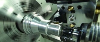
Main types of work on a lathe 1616:
- Turning of external and internal cylindrical and conical surfaces of varying complexity and configuration.
- Turning the ends of workpieces.
- Turning of conical shaped surfaces.
- Cutting metric, modular and inch threads with a cutter.
- Cutting metric and inch threads with a tap and die.
- Corrugation of surfaces.
- Grooving.
- Drilling, countersinking and reaming of holes.
It is also possible to process parts by rotating the workpiece relative to the cutting tool. On the 1616 lathe you can process not only metal, but also workpieces made of other materials.
Operations are performed with carbide nozzles and devices made of high-speed tool metals.
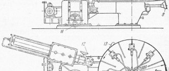
The operating principle of the 1616 lathe can be represented as the following algorithm:
- Fixing the workpiece in the machine chuck or between its centers.
- Fastening the cutters in the tool holder on the caliper.
- Attaching the appropriate tool (for drilling, boring, internal threading) to the tailstock quill.
- Processing of a workpiece by combining two movements - translational movement of the cutting tool and rotation of the part. Due to these movements, it is possible to process parts of cylindrical, conical and shaped configurations, helical surfaces and ends.
The device of a screw-cutting lathe 1A616
This manual is an electronic version in PDF format of the original paper version. This documentation contains a detailed description of the design of the 1A616 universal screw-cutting lathe.
Contents of this documentation:
- General characteristics of the machine
- Machine device
- Machine kinematics
- Cutting movement
- Serving movements
- Movement of helical surface formation
- Auxiliary movements
- Machine layout
- Gearbox
- Headstock
- Gearbox
- Apron
- Caliper
- Tailstock
You can download the Design of a screw-cutting lathe 1A616 (11 pages) in excellent quality from the link below:
Documentation
The documentation for the 1616 lathe includes:
- Passport.
- Purpose and scope.
- Unpacking and transportation.
- Machine foundation, assembly and installation.
- Preparing for initial launch.
- Description of the main components.
- Lubrication.
- Initial launch.
- Safety instructions.
- Setup.
- Regulation.
- List of equipment.
Personnel without appropriate qualifications are not allowed to work on the 1616 lathe. Operating rules must be observed both during commissioning and during ongoing operations:
- The oil level is checked and topped up if necessary.
- During constant cooling work, the appropriate composition is poured into the system and the presence of a storage tray is checked.
- A control inspection of the power cables and connection to the power source is carried out.
- A visual inspection of components and necessary equipment is carried out.
During work, safety rules are observed:
- While the 1616 lathe is operating, you must not touch the handles located on the gearbox and tailstock.
- When processing parts, be sure to use a protective screen mesh.
- When processing centered parts with clamps, you must use a special chuck with a protective rim.
- The machine doors must be tightly closed while processing the workpiece.
Passport
DjVu file format
Basic equipment
| Disks with programs for controlling the machine NC-studio and Artcam Operating instructions for the milling and engraving machine | Water pump for spindle cooling | Hoses for connecting the pump to the spindle |
| Set of cutters and collets. ER11 collets (3.175 mm and 6 mm) and collet nut | Clamps for fastening the workpiece on the work table (4 pcs.) | Open-end wrenches for securing the tool in the collet and hex keys |
| NC-studio board | Power cable | USB interface cable for connecting the machine to a computer |
User reviews
Roman, Moscow: I have been working on a 1616 lathe for more than 10 years. I note the high accuracy of processing; there were no major problems with it. Vasily, Yekaterinburg: It copes well with large volumes. We work together on the 1616 lathe. Both have been trained, there are no complaints about the machine. You can perform complex turning jobs, not just nuts and bolts. Alexander, Volgograd: Lathe 1616 deserves respect as a veteran of metalworking equipment. I bought it far from new, I had to restore it. Now it works like a charm, serves perfectly, no complaints.
User manual
16a16 screw-cutting lathe: diagram
How accurately the machine will work depends on whether it was installed correctly. The unit must be thoroughly secured with special bolts to the foundation or concrete pad with a height of at least 150 mm. In this case, the machine must be checked in accordance with GOST 42 - 56.
The first start-up of a lathe is no less important than the process of installing and straightening it. The start-up is also considered initial if the equipment has been idle for a long time and not maintained. To avoid breakdowns, treat the initial start-up with special care and responsibility. The initial launch preparation process is a sequential process.
Step 1. Thoroughly clean off any corrosion deposits, if any, on the opening and other exposed parts.
Step 2: Check for oil and add it if necessary.
Stage 3. If turning operations with cooling are planned, then a special coolant must be added to a special tank.
Step 4. Check the integrity of the electrical wires and the reliability of their connections.
Stage 5. After successfully completing the above steps, you can turn on the machine and perform turning work.
The general operating process of the 1A616 machine can be divided into the following key points.
Stage 1. The workpiece must be securely fixed between the centers of the chuck or in it itself.
Stage 2. Selected modifications of the cutters are also carefully secured in a special clamp located on the equipment support. No more than four threading tools should be installed in the holder at a time.
Stage 3. The tools necessary for internal threading, drilling and boring are secured in the tailstock quill.
Stage 4
Now it is important to correctly set the required spindle speed. Its correction is carried out by special switches located on the gearbox
Stage 5. The chassis comes into operation by pressing the start button located on the gearbox.
Step 6. To obtain different thread pitches, appropriate adjustments are made on the gearbox handles and by replacing gears.
Stage 7. When turning on the unit responsible for increasing the thread pitch, you need to sharply turn the feed reverse lever to the right.
Stage 8. The headstock handle must be installed in a position that will correspond to the o.