How many types of metal cutting machines are there?
Table of commercially produced machines divided into nine groups of nine types
| Machine tools | Group | Types of machines |
| Turning | 1 | Specialized for shaped products |
| Drilling and boring | 2 | Horizontal drilling |
| Grinding, polishing, finishing | 3 | Lapping and polishing |
| Combined | 4 | Anode-mechanical |
Classification and designation system of metal-cutting machines
Metal-cutting machines, depending on the type of processing, are divided into nine groups, and each group into ten types (subgroups), characterizing the purpose of the machines, their layout, the degree of automation or the type of tool used. For example, group 4 is intended for electroerosive, ultrasonic and other machines.
The machine model designation consists of a combination of three or four numbers and letters. The first digit means the group number, the second - the subgroup number (machine type), and the last one or two digits - the most characteristic technological parameters of the machine.
For example:
1E116
— means a single-spindle turret lathe with the largest diameter of the processed bar being 16 mm;
2Н125
- means a vertical drilling machine with the largest nominal drilling diameter of 25 mm;
2G103P
is a high-precision desktop vertical drilling machine with the largest nominal drilling diameter of 3 mm.
The letter after the first digit indicates different versions and modernization of the main basic model of the machine. The letter at the end of the digital part means a modification of the base model, the accuracy class of the machine or its features.
Machine accuracy classes mean:
N
- normal;
P
- increased, accuracy 0.6 deviations from N;
B
– high, accuracy 0.4 deviations from H;
A
- especially high accuracy, accuracy 0.25 deviations from H;
C
- especially precise machines, accuracy 0.16 deviations from N.
P, V, A, S
— precision machines (high accuracy).
The following indexing of models of computer-controlled machine tools is accepted:
C
— with cyclic control;
F1
- with digital position indexing, as well as with a preliminary set of coordinates;
F2
- with a CNC positional system,
FZ
- with a CNC contour system;
F4
- with a combined CNC system.
For example:
16D20P
— high-precision screw-cutting lathe;
6Р13К-1
- vertical milling console machine with a copying device;
1G340PTs
- turret lathe with a horizontal head, increased accuracy, with cyclic program control;
2455AF1
- coordinate-boring two-column machine of particularly high accuracy with a preliminary set of coordinates and digital display;
2R135F2
- vertical drilling machine with a turret head, a cross table and a positional numerical control system;
16K20FZ
- lathe with a contour numerical control system;
2202VMF4
is a multi-purpose (drilling-milling-boring) horizontal high-precision machine with a tool magazine and a combined CNC system (the letter M means that the machine has a tool magazine).
Machines are divided into universal (general purpose), widely universal (limited number of operations), specialized (one name), special and aggregate (made up of interchangeable units).
Special and specialized machines are designated by a letter index (of one or two letters) assigned to each plant, with the model number of the machine. For example, mod. MSh-245 is a semi-automatic rack grinder with increased precision produced by the Moscow Grinding Machine Plant.
Based on weight, machines are divided into the following categories:
before 1
t - light;
up to 10
t - average;
up to 30
t - large;
up to 100
t - heavy;
St. 100
t is unique.
at the same time, up to 5
tons are transportable;
St. 5
t - not transportable.
By degree of automation:
with manual
— worker commands are needed;
semi-automatic
- only for adjustment, installation and removal of workpieces;
automatic
- without the participation of a worker from installing a
CNC
- semi-automatic or automatic, controlled according to a pre-compiled and easily replaceable program.
CLASSIFICATION OF METAL-CUTTING MACHINES
| Machine tools | Group | Machine type | Purpose of the machine |
| LATHE | 1 | 0 | specialized automatic and semi-automatic machines |
| 1 | single-spindle automatic and semi-automatic machines | ||
| 2 | multi-spindle automatic and semi-automatic machines | ||
| 3 | turning-turret | ||
| 4 | semi-automatic turning-turret | ||
| 5 | carousel | ||
| 6 | turning and loboturning | ||
| 7 | multi-cutting and copying | ||
| 8 | specialized | ||
| 9 | different lathes | ||
| DRILLING AND BORING | 2 | 0 | — |
| 1 | benchtop and vertical drilling | ||
| 2 | semi-automatic single-spindle | ||
| 3 | semi-automatic multi-spindle | ||
| 4 | jig boring | ||
| 5 | radial and coordinate drilling | ||
| 6 | boring | ||
| 7 | finishing and boring | ||
| 8 | horizontal drilling | ||
| 9 | different drilling | ||
| GRINDING, POLISHING, FINISHING, SHARPENING | 3 | 0 | — |
| 1 | cylindrical grinding, centerless grinding | ||
| 2 | internal grinding, coordinate grinding | ||
| 3 | roughing and grinding | ||
| 4 | specialized grinding machines | ||
| 5 | longitudinal grinding | ||
| 6 | sharpening | ||
| 7 | flat grinding | ||
| 8 | lapping, polishing, honing, finishing | ||
| 9 | various machines working with abrasives | ||
| ELECTROPHYSICAL, ELECTROCHEMICAL | 4 | 0 | — |
| 1 | — | ||
| 2 | light beam | ||
| 3 | — | ||
| 4 | electrochemical | ||
| 5 | — | ||
| 6 | — | ||
| 7 | electroerosive, ultrasonic piercing | ||
| 8 | anodic-mechanical cutting | ||
| 9 | — | ||
| GOOTH and THREAD MACHINING | 5 | 0 | thread-cutting |
| 1 | gear shaping machines for cylindrical wheels | ||
| 2 | gear cutters for bevel wheels | ||
| 3 | Gear hobbing machines for cylindrical wheels and splined shafts | ||
| 4 | for cutting worm wheels | ||
| 5 | for machining the ends of wheel teeth | ||
| 6 | thread-milling | ||
| 7 | gear finishing, checking and rolling | ||
| 8 | gear and thread grinding machines | ||
| 9 | various gear and thread machining tools | ||
| MILLING | 6 | 0 | drum-milling |
| 1 | vertical milling console | ||
| 2 | continuous milling machines | ||
| 3 | longitudinal single-post | ||
| 4 | copying and engraving machines | ||
| 5 | vertical milling non-cantilever | ||
| 6 | longitudinal two-post | ||
| 7 | console-milling operating rooms | ||
| 8 | horizontal milling console | ||
| 9 | different milling | ||
| PLANING, SLOTTING, broaching | 7 | 0 | — |
| 1 | longitudinal single-post | ||
| 2 | longitudinal two-post | ||
| 3 | cross-planing | ||
| 4 | slotting | ||
| 5 | lingering horizontal | ||
| 6 | broaching vertical for pulling internal | ||
| 7 | broaching vertical for pulling outer | ||
| 8 | — | ||
| 9 | various planing machines | ||
| CUTTING | 8 | 0 | — |
| 1 | cutting, working with a cutter | ||
| 2 | cutting-off machines working with an abrasive wheel | ||
| 3 | smooth or grooved disc | ||
| 4 | correct-cutting | ||
| 5 | band saws | ||
| 6 | cutting-off with circular saw | ||
| 7 | cutting-off hacksaws | ||
| 8 | — | ||
| 9 | — | ||
| DIFFERENT | 9 | 0 | — |
| 1 | pipe and coupling processing | ||
| 2 | saw-cutters | ||
| 3 | straight- and centerless-grinding | ||
| 4 | — | ||
| 5 | for testing tools | ||
| 6 | dividing machines | ||
| 7 | balancing | ||
| 8 | — | ||
| 9 | — |
Who works on the machines?
Milling operator (from German Fräser; machine operator) is a specialist in working on a milling machine.
Interesting materials:
What holiday is celebrated on June 12 in Russia? What percentage does Russian Post take for cash on delivery? What percentage of Russia's income comes from oil? What percentage of city residents live in Russia? What is the percentage of mineral resources in Russia? What is the divorce rate in Russia? Which region is the main fuel base of Russia? What Russian flag was there under the Tsar? Which Russian Kremlin is included in the UNESCO list? What is the highest quality Russian chocolate?
Code of turning machines
When designating the code for machines in a turning group, the first digit 1 indicates the group of machines. The second number indicates the type of lathe. The subsequent numbers, as a rule, show the technological parameter of the machine, namely: the maximum diameter of the workpiece, the height of the centers, etc. The letter after the first or second code can symbolize the generation of the machine, the manufacturer or modification. The letter placed at the end of the digital code may indicate an improvement in the base model or the accuracy class of the machine.
Here are some examples of the designation of lathe models.
1K62 - number 1 - group of lathes; 6 — turning and wine-cutting machine; 2 — height of centers, dm; letter K - generation.
1A616 - figure - group of lathes; 6 — screw-cutting lathe; 16 — height of centers, cm; A - generation.
1B811 - number 1 - group of lathes; 8 — turning and backing; 1 - technological parameter that determines the dimensions of the workpieces being processed; B - generation.
16K20P - number 1 - group of lathes; 6 — turning screw-cutting; 20 — height of centers, cm; K - generation; P - accuracy class - increased.
It should be noted that the sixth type of machines includes screw-cutting lathes, and the eighth type includes backing lathes. In the machine tool industry, the majority of manufactured metal-cutting machines, including lathes, are manufactured according to state standards; in which the main parameters correspond to normal or size ranges. By dimensional or normal series we mean a group of similar machines, consisting mainly of standardized units and parts, each of which is designed for processing parts of certain sizes,
The size ranges (standard sizes) of universal screw-cutting lathes and two-column rotary lathes are given in table. 1.
Table 1.
The table shows that the main parameter that determines the standard sizes of machines is the dimensions of the installed part. Moreover, each subsequent standard size of the machine makes it possible to process a part with a diameter 1.26 times larger than that of the previous part. Thus, for universal screw-cutting lathes and rotary machines, the denominator of the size range is set to 1.26. In other words, the series of numbers is 250; 320; 400; 500; 630; 800; 1000 (2300; 3200; 4000; 5000; 6300; 8000) form a geometric progression with a denominator of 1.26.
The maximum height of the installed part on rotary machines also changes according to the law of geometric progression with a denominator equal to 1.26: 2000, 2500, 3200. The presence of two naturally changing main parameters: the largest diameter of the installed part and its heights makes it possible to also regularly change other technical characteristics machine: power of the main drive, weight of the installed part, etc.
According to the degree of specialization, all machines are divided into universal, specialized and special.
Universal machines are machines that can perform various operations on a wide range of parts.
Specialized are machines that can perform a limited number of operations on parts of the same type.
Special machines are machines designed to perform a limited number of operations on parts of one standard size.
Classification of metal-cutting machines - all about equipment for metal processing
Metal-cutting machines produced by domestic manufacturers are divided into several categories, which are characterized by the corresponding classification. You can determine which category this or that equipment belongs to by its labeling, which says a lot to those who understand it. However, no matter what category the metal-cutting device belongs to, the essence of processing on it comes down to the fact that the cutting tool and the part perform form-building movements, and it is they that determine the configuration and dimensions of the finished product.
The most common types of metal-cutting machines: 1-6 - lathes, 7-10 - drilling, 11-14 - milling, 15-17 - planing, 18-19 - broaching, 20-24 - grinding.
Classification of machines by degree of versatility.
There are the following machines: universal ones, which are used for the production of parts of a wide range with a large difference in size.
Such machines are adapted for various technological operations:
- specialized, which are intended for the manufacture of parts of the same type, for example, body parts, stepped shafts similar in shape, but different in size;
- special ones, which are designed for the manufacture of one specific part or one shape with a slight difference in size.
Identification of the object of assessment
Classification of machines helps to accurately identify the object during evaluation. In this case, identification is understood as establishing identity between what is written in a document (passport, inventory card, description) and what actually exists. Identification of objects of assessment means, firstly, compiling or clarifying a list of assessed pieces of equipment based on their actual availability, i.e. carrying out a kind of inventory; secondly, checking and bringing into conformity with the real state of the basic initial information about the objects being assessed.
The identification work includes the following steps.
1. Clarification of the general characteristics of the equipment being assessed in accordance with the assessment assignment and the formation of an inventory list of the equipment being assessed.
2. Collection and verification of technical and other data for each object. Technical characteristics and parameters of objects can be presented both in expanded form and in abbreviated form - it all depends on the purpose of the assessment and the significance of the object being assessed.
For example, the most complete list of technical information about metalworking equipment is as follows:
- group, subgroup, type of equipment: general name and code according to the OKP and OKOF classifiers;
- name and model of the machine;
- Overall dimensions, mm;
- weight of the structure, t;
- main parameter and main technical characteristics;
- additional devices: for example, type and characteristics of CNC;
- electric motor power, kW;
- standard service life, years;
- repair complexity, units of repair complexity (u.r.s.) of mechanical, hydraulic, electrical parts;
- development organization;
- manufacturer
Classification of machines by degree of automation.
There are automatic and semi-automatic machines. An automatic machine is a machine in which, after adjustment, all movements necessary to complete the processing cycle, including loading blanks and unloading finished parts, are carried out automatically, i.e. performed by machine mechanisms without operator participation.
The operating cycle of the semi-automatic machine is also carried out automatically, with the exception of loading and unloading, which is performed by the operator, who also starts the semi-automatic machine after loading each workpiece.
For the purpose of comprehensive automation, automatic lines and complexes are created for large-scale and mass production, combining various machines, and for small-scale production, flexible production modules (GPM).
Automation of small-scale production of parts is achieved by creating machines with program control (cyclic), the letter C (or the numeric letter F) is introduced into the designation of models. The number after the letter F indicates a feature of the control system:
- F1 - a machine with a digital display (showing numbers reflecting, for example, the position of the movable part of the machine) and a preliminary set of coordinates;
- F2 - a machine with a positional or rectangular system;
- F3 - machine with a contour system;
- F4 is a machine with a universal system for positional and contour processing, for example, model 1B732F3 is a lathe with a CNC contour system.
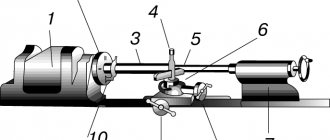
Design features of lathes
Metalworking equipment consists of the following structural parts:
- a frame on which all components of the unit are installed;
- an apron, where the movement of the lead screw/roller is converted into the movement of the support;
- headstock;
- a support on which the cutting organ is located;
- gearbox, which serves to transmit movement to the caliper;
- electrical unit of the machine.
One of the key advantages of the lathe structure is that the structural elements of the unit are unified. This greatly simplifies the process of its maintenance and repair.
Machine markings
The classification of equipment intended for processing metal workpieces assumes that, having seen its markings, any specialist will immediately be able to tell which metal-cutting machine is in front of him. This marking contains alphabetic and numerical symbols that indicate individual characteristics of the device.
The first number is the group to which the metal-cutting machine belongs, the second is the type of device, its type, the third (and in some cases the fourth) is the main standard size of the unit.
Decoding the markings of metal-cutting machines
After the numbers listed in the model marking, there may be letters that determine whether the model of the metal-cutting machine has special characteristics. These characteristics of the device may include its level of accuracy or indication of modification. Often in the designation of a machine, the letter can be found after the first digit: this indicates that this is a modernized model, in the standard design of which some changes have been made.
As an example, you can decipher the markings of the 6M13P machine. The numbers in this designation indicate that we have a milling machine (“6”) of the first type (“1”), which belongs to the 3rd standard size (“3”) and allows processing with increased accuracy (letter “P” ). The letter “M” present in the marking of this device indicates that it has been modernized.
Machine numbering
In the USSR, a unified system of machine symbols was adopted, based on assigning a code (number) to each machine model. The numbering of metal-cutting machines, developed by the Experimental Research Institute of Metal-Cutting Machines (ENIMS), is based on a nine-digit system. All machines are divided into 9 groups, each group is divided into 9 types and each type - 9 10 standard sizes. The number assigned to each machine model can consist of three or four numbers and letters, and the letters can appear after the first digit or at the end of the number, for example: 612, 1616, 6N82, 2620, 6N12PB.
The first digit of the number indicates the group to which the machine belongs. The second digit indicates the type of machine in this group. The third or third and fourth digits together indicate the conditional size of the machine.
Classification
Metal-cutting machines, depending on the nature of the work performed and the type of cutting tools used, are divided into 11 groups (see figure).
- The group of lathes (items 1 - 6) consists of machines designed for processing rotating surfaces. The unifying feature of the machines of this group is the use of the rotational movement of the workpiece as a cutting movement.
- The group of drilling machines (items 7 - 10) also includes boring machines. The unifying feature of this group of machines is their purpose - processing round holes. The cutting movement is the rotational movement of the tool, which is usually also accompanied by a feed movement. In horizontal boring machines, feed can also be carried out by moving the table with the workpiece.
- The group of grinding machines (items 20 - 24) is united based on the use of abrasive grinding wheels as cutting tools.
- The group of polishing and finishing machines is united on the basis of the use of abrasive bars, abrasive belts, powders and pastes as cutting tools.
- The group of gear-processing machines includes all machines that are used for processing wheel teeth, including grinding machines.
- The group of milling machines (items 11 - 14) consists of machines that use multi-blade tools - cutters - as cutting tools.
- The group of planing machines (items 15 - 17) consists of machines whose common feature is the use of a rectilinear reciprocating movement of the cutter or workpiece as a cutting movement.
- The group of cutting machines includes all types of machines designed for cutting and sawing rolled materials (rods, angles, channels, etc.).
- The group of broaching machines (lines 18 and 19) has one common feature: the use of special multi-bladed tools—broaches—as a cutting tool.
- The group of thread-processing machines includes all machines (except for turning machines) designed specifically for the production of threads.
- The group of miscellaneous and auxiliary machines combines all machines that do not belong to any of the groups listed above.