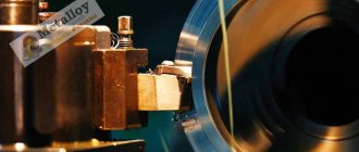
Enormous technological capabilities for the production of high-quality metal parts, characterized by high accuracy of their geometric parameters, are provided by a modern CNC lathe. Such machines, produced by domestic as well as foreign manufacturers, are characterized by high efficiency and exceptional reliability.
CNC lathe with 12 position turret
Design features of the machines
CNC lathes, used today in many manufacturing enterprises, are modern equipment that allows processing of metal parts with high precision. This is ensured by the following design features of such equipment:
- there are almost no gaps in the drive transmission devices of such machines;
- all load-bearing elements, components and mechanisms included in the design of a CNC lathe have high rigidity;
- the kinematic chains of the equipment are specially designed so that their length is minimal, as well as the number of mechanical gears that make them up is minimal;
- The design of turning units includes special signaling devices responsible for feedback;
- such devices are characterized by increased resistance to vibration loads that necessarily arise during their operation;
- Hydraulic, as well as other components of turning equipment, are preheated before starting work using special systems, which minimizes the risk of thermal deformation during processing.
CNC lathes are equipped with guides that are characterized by increased wear resistance and a reduced coefficient of friction, which is very important for ensuring high accuracy of metal turning operations. Thanks to these characteristics of the unit’s guides, the level of mismatch in its control system is reduced, and all moving mechanisms move according to the specified parameters with maximum accuracy.
The guide units of a lathe, where rolling elements are provided, which are mainly used as rollers, are designed and manufactured so that when operating at high speeds and when they are intensely heated, the coefficient of friction in them remains unchanged.
Hardened machine bed guides TRENS-SE-520
Naturally, the guides of lathes, on which metal parts are processed at high speeds, must be characterized by increased rigidity. This requirement is ensured due to the fact that the guides are subject to preload, which is performed using special control mechanisms. To reduce friction forces in the guide units of the unit’s support and its frame, which operate on the sliding principle, they are made from pairs of materials: high-quality wear-resistant plastic (usually fluoroplastic) plus cast iron or steel.
The guides of lathes equipped with CNC systems can be located in horizontal, vertical or inclined planes. Depending on this, the unit models are assigned to a certain category.
To provide high rigidity to the load-bearing elements of CNC turning equipment, they are made in a box-shaped form with mandatory transverse and longitudinal internal ribs. For the manufacture of these elements, casting and welding technologies are used. If previously only cast iron or steel were used to make the load-bearing elements of metal lathes, now many foreign manufacturers make columns, beds, as well as slides of such units from concrete with the addition of polymers or artificial granite, which gives them high rigidity and increased resistance to vibration loads
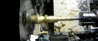
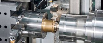
The most important element of any metal-cutting equipment, including turning equipment, is the spindle assembly, which experiences significant loads during operation. That is why all the base and seating surfaces of such a unit, as well as its necks, must be characterized by increased wear resistance. The bearings, which are installed in the supports of the unit, ensure the accuracy of its rotation; increased demands are placed on them in terms of the degree of their wear resistance.
Headstock with chuck for machine SN-500
On lathes equipped with a CNC system, the spindle assembly is characterized by a more complex design.
This is explained by the fact that a number of additional ones are installed in this element: clamping mechanisms for working devices operating in automatic mode, indicators responsible for self-diagnosis of equipment and for adaptive control over the processing process. On lathes of this category, the spindle assembly (along the axis of its rotation) can be located in a horizontal as well as a vertical plane.
How to choose?
In order to correctly select a machine for metal processing, it is necessary to carefully study the design features of the available models and study their characteristics.
First of all, you should pay attention to the following parameters:
- parts configuration;
- accuracy and quality of surface treatment;
- machine dimensions;
- maximum weight of workpieces;
- available processing modes;
- device power;
- planned production volume;
- machine performance.
Marking of CNC turning equipment
The automated control system for turning group machines can be organized according to three main schemes.
Contour
This scheme involves programming the trajectory of movement (including curved) of the working tool and monitoring the correct implementation of this procedure.
Positional
When implementing such a scheme, the coordinates of the points where the working tool should end up after performing a certain technological operation are programmed.
Adaptive
This scheme involves combining the operating principles of the previous two.
Based on the marking of domestic turning equipment equipped with CNC, it is quite easy to determine the category of such a device.
The alphanumeric designation at the end of the marking indicates precisely the system by which numerical control is organized in this machine:
- F1 - machines in which the working tool moves along predetermined coordinates, while they provide a digital indication;
- F2 - models where the tool movement is implemented according to a positional scheme;
- F3 - turning equipment, which implements a contour circuit for controlling the movement of the tool;
- F4 - models of CNC lathes with an adaptive (universal) control system.
Marking of CNC lathes
In the marking of some models of CNC lathes you can find the alphanumeric designation C1-C5, which indicates that such equipment is distinguished by special technological capabilities. In particular, models whose markings contain the designations C1 and C2 have a low feed limit and a small range of their adjustment. But units whose markings contain the symbols C3, C4 and C5T, on the contrary, have an increased feed range and are distinguished by wide possibilities for their adjustment.
Thanks to their advanced capabilities, machine models marked with the symbols C4 and C5 can be used to effectively perform many technological operations, for example, cutting external and internal threads, processing workpieces that have a cylindrical, conical and shaped shape, including stepped ones. It is worth noting that such mills can process both external and internal surfaces, which differ in the complexity of their configuration.
Features of machine programming
In order for the use of lathes equipped with a CNC system to be as efficient as possible, it is necessary to carefully develop the technological processing process, as well as create a program that will control the operation of the equipment. When solving these issues, it is necessary to take into account a number of important parameters: the need to link the coordinate systems of the equipment, the location of the workpiece being processed on it, and the initial position of the working tool with its further movements, which it must automatically perform during the work process.
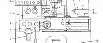
Principle of numerical control of a lathe
When drawing up a program for such a machine, it is taken into account that the working tool moves along the coordinate axes of the workpiece, which is in a stationary state. What is important is that it moves in a linear direction along axes parallel to the axes of the workpiece being processed.
The essence of programming a separate technological operation performed on such a machine is that the computer program describes the route that the cutting tool must take in order to form a part with the given geometric parameters.
When compiling such a program, the following algorithm is followed.
- The technological process is divided into three stages: roughing, finishing and finishing. In order to increase the productivity of work and reduce their labor intensity, they try to combine roughing and finishing operations.
- To minimize errors in fixing and positioning the workpiece, its technological and design bases are combined according to certain rules.
- It is advisable to perform complete turning of a part with a minimum number of settings.
- It is necessary to adhere to a rational approach to the processing of workpieces. This involves, for example, turning parts of cylindrical and conical workpieces with low rigidity only after processing their areas of sufficient rigidity.
In a technological process that involves the use of CNC-equipped lathes for processing, a separate operation refers to processing performed on one machine. In this case, such operations can be divided into separate transitions, subdivided into independent passages.
The transitions that a CNC-equipped lathe can perform are divided into positional, elementary, instrumental and auxiliary.
There are certain rules for developing programs for the sequence of work with the workpiece being processed, adhering to which you can ensure high quality of the finished product. In accordance with these rules, the following parameters are set in the computer program for the lathe: the number of transitions and passes, the total number of settings, the type of processing to which the workpiece is subjected, the number of cutting elements and their standard sizes. If the technical capabilities of the equipment allow, then it is advisable to place all the tools involved in the work in one tool holder.
SAUTER turret for CNC lathe
But the tool holders of the unit do not always allow the installation of all the elements that are involved in processing. In such cases, which are not very rare, the control program provides for a suspension of work, which is necessary to replace the tool. In addition, when using such machines, it is possible to split the processing process into several parts, so as not to pause it to change tools. Most models of lathes with CNC systems are equipped with tool holders in which a limited set of cutting tools can be fixed. In most cases, to operate such devices, a tool equipped with multifaceted cutting inserts is used. To quickly put it in order if the cutting edge is worn out, just turn the plate and continue working.
Among the most common tools that are equipped with CNC turning units, the following can be noted: for boring - cutters, the cutting plates of which are welded or secured mechanically; for thread cutting - triangular prefabricated cutters; for processing holes and performing trimming - rhombic cutters with carbide plates. All tools are installed in the tool holder in the sequence in which they are involved in processing. The reference point specified in the computer control program is the rounding at the tip of the cutter or its tip itself.
CNC lathe DMTG model CKE6150Z
Feedback subsystem
The main elements of the feedback subsystem are sensors that function as a measuring system. They control the position and speed of the knife. The control unit receives signals and creates new ones, based on calculating the difference between the current and specified parameters.
Help : The main task of the feedback system is to provide the US with information about the current position of the actuator of the device and the speed at which the motors operate.
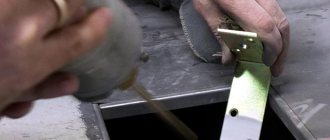
Drives and accessories
In CNC lathes of low and high power, various types of electric motors are used, which drive the main movement. In the first case, DC electric motors are predominantly used, in the second - alternating current. Domestic manufacturers producing machines in this category equip them with asynchronous electric motors with four poles, which are capable of operating without failure even in the most difficult conditions: in the presence of oil particles, metal dust and small chips in the surrounding atmosphere. Such electric motors are not afraid of critical overloads, which they successfully withstand.
Drive mechanism of benchtop lathe D250x550 CNC
To drive the feed mechanism of CNC lathes, electric motors of synchronous and asynchronous types are used, but most often they use motors of the first type, equipped with feedback indicators, braking elements, and magnets made of rare earth chemical elements. To control such motors, digital converters are used in the electrical circuit of lathes.
If an asynchronous motor is installed on the equipment, a frequency converter assembled on microprocessors is required to control it. When using such electric motors, a special programmer is installed on the machines, equipped with a graphic or digital screen.
Trens lathe control panel
On lathes controlled by computer programs, auxiliary devices must be installed, which include:
- loading mechanisms;
- mechanisms for clamping the workpiece;
- lubricating devices;
- devices designed to remove chips that are formed during the processing process;
- mechanisms designed for quickly changing tools.
Unlike similar devices used on conventional machines, these devices are characterized by high productivity and reliability of their operation.
Working principle of CNC
The functioning of the CNC machine is carried out in the following sequence:
- To begin with, the part processing program is entered into the device’s control unit.
- It carries out the entire data processing process, prepares all motion commands and sends them to the drive system.
- The drive controls the movement and speed of the product blocks.
- The feedback system remembers data about the location and speed of movement of the axes and sends a signal to the control unit.
- The BUS compares the feedback signals with the initial ones and if there are errors, it corrects them and sends new signals to the execution mechanism to correct the process.
- A control panel with a screen is used to view commands by the operator.