ang=»ru»>
Color wiring diagram of screw-cutting lathe 16K20VF1
It is difficult to understand an electrical circuit with many similar elements. To make it easier to find the desired element on the diagram, as well as to distinguish elements marked the same way, I added colored geometric shapes to the designations. Identical shapes mean that the elements next to them belong to the same device (for example, a contactor, relay or switch). I call this technology colorism. I made the description in two versions: I made the description in two versions:
- One with the need to scroll. I did this so that when reading the description the diagram would not go out of sight).
- Other traditional
Use the form that you find more convenient. The machine's passport with a description of the electrical circuit can be easily found on the Internet.
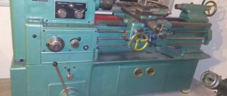
Screw-cutting lathe 16K20
The 16K20 screw-cutting lathe is designed to perform a variety of turning operations: turning and boring cylindrical and conical surfaces, cutting external and internal metric, inch, modular and pitch threads, as well as drilling, countersinking, reaming, etc. Deviation from cylindricity is 7 microns, taper is 20 microns at a length of 300 mm, deviation from straightness of the end surface at a diameter of 300 mm is 16 microns. However, there are 16K20 machines without a lead screw. On such machines you can perform all types of turning work, except for cutting threads with a cutter.
The machines are equipped with a mechanical clutch, a drive for rapid movements of the caliper, the tailstock has aerostatic unloading, the bed guides are hardened HRCе 49...57.
The technical parameters by which screw-cutting lathes are classified are the largest diameter D of the workpiece (part) being processed or the height of the centers above the bed (equal to 0.5 D), the greatest length L of the workpiece (part) being processed and the weight of the machine. A number of the largest processing diameters for screw-cutting lathes look like: D = 100, 125, 160, 200, 250, 320, 400, 500, 630, 800, 1000, 1250, 1600, 2000 and further up to 4000 mm. The greatest length L of the workpiece is determined by the distance between the centers of the machine. Manufactured machines with the same value of D can have different values of L. By weight, lathes are divided into light - up to 500 kg (D = 100 - 200 mm), medium - up to 4 tons (D = 250 - 500 mm), large - up to 15 t (D = 630 - 1250 mm) and heavy - up to 400 t (D = 1600 - 4000 mm). Lightweight lathes are used in tool production, instrument making, the watch industry, and in experimental and experimental workshops of enterprises. These machines are available with or without mechanical feed.
Characteristics of machine components
Machine device
At the first stage of familiarization with the capabilities of the 16K20 machine, it is recommended to study the technical data sheet of the equipment. The main parameters in this case are the maximum and minimum size of the workpiece and the characteristics of the displacement of the caliper relative to it.
The diameter of the part above the frame should not exceed 40 cm. The same value when located above the support cannot be more than 22 cm. Considering the rather small dimensions of the equipment (279.5 * 119 * 150 cm) and weight 3010 kg, these parameters are optimal for this type machine tools
But besides this, when choosing the optimal operating mode after studying the kinematic diagram, you should familiarize yourself with the passport characteristics of the spindle:
- hole diameter – 5.2 cm;
- rotation frequency. With direct rotational motion, this parameter can vary from 12.5 to 1600 rpm. During reverse – from 19 to 1900 rpm;
- number of speeds. The number of direct lines is 11. There are two times less reverse ones - 11;
- flange diameter – 17 cm;
- maximum possible torque, Nm – 1000.
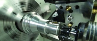
Processing of a rotating workpiece is carried out due to the movement of the support on which the cutting tool is fixed. An important point is the correct choice of the kinematic operating scheme, which is described in detail in the passport.
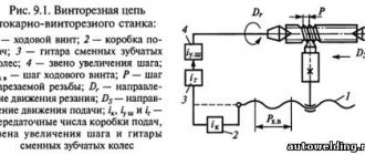
Kinematic diagram
To operate the machine, you need to know the descriptions of the following caliper parameters:
- maximum offset length. Longitudinal can be 64.5, 93.5, 133.5 and 193.5 cm. Transverse - 30 cm;
- speed of rapid movements, mm/min: 3800 – for longitudinal; 1900 – for transverse;
- feed range, mm/rev. For longitudinal ones it is limited from 0.05 to 2.8. Transverse – from 0.025 to 1.4;
- the number of innings is the same for both directions and is 42;
When choosing an operating mode, the maximum permissible workpiece weight should be taken into account. If it is mounted in a cartridge, then its weight should not exceed 200 kg. The weight range for machining centers is wider and can range from 460 to 1300 kg depending on the length of the part.
According to the datasheet, the cutting slide has a maximum rotation angle of ±90°. The permissible value of the cutter holder dimensions is 25*25 mm.
Technical characteristics of the machine 16K20
The technical characteristics of the 16K20 machine are the main indicator of the machine’s suitability for performing certain jobs. For screw-cutting lathes, the main characteristics are:
- largest diameter D of the workpiece (part) being processed
- greatest distance between RMC centers
- maximum length of the workpiece
- spindle revolutions per minute
Below is a table with the technical characteristics of the 16K20 screw-cutting lathe. More detailed technical characteristics of the screw-cutting lathe can be found in the passport of the machine 16K20
| Quantities | ||
| Accuracy class | N | |
| The largest diameter of the workpiece being processed above the bed | mm | 400 |
| Largest turning diameter over cross slide | mm | 220 |
| The largest diameter of the processed bar | mm | 50 |
| Maximum length of the processed product | mm | 710, 1000, 1400, 2000 |
| Spindle speed limit | rpm | 12,5-1600 |
| Feed Limits | ||
| - longitudinal | mm/rev | 0,05-2,8 |
| - transverse | mm/rev | 0,025-1,4 |
| The greatest force allowed by the feed mechanism at the stop | ||
| - longitudinal | kgf | 800 |
| - transverse | kgf | 460 |
| The greatest force allowed by the feed mechanism on the cutter | ||
| - longitudinal | kgf | 600 |
| - transverse | kgf | 360 |
| Main drive motor power | kW | 11 |
| Machine dimensions (Length) | ||
| - length | mm | 2505, 2795, 3195, 3795 |
| - width | mm | 1190 |
| - height | mm | 1500 |
| Machine weight | kg | 2835, 3005, 3225, 3685 |
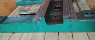
Design features
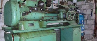
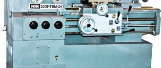
Appearance
Initially, the 16K20 screw-cutting lathe was developed to perform standard operations - turning the surfaces of parts, forming threads of various types. For this purpose, the installation of blanks is provided in the center and on the chuck mechanism.
To analyze the capabilities of the equipment, it is recommended to study the passport and photo. The design features are a rigid frame, made in the shape of a box, and hardened, ground guides. These components are installed on a monolithic base. Thanks to this arrangement, the productivity of the 16K20 series machine is significantly higher than that of its earlier counterpart - 1K62.
In addition to the improved kinematic diagram, the following technical characteristics of the 16K20 machine can be noted:
- spindle head. Makes it possible to choose one of four rows of speeds with different limit options;
- flanged front end of the spindle. It is mounted in precision rolling bearings. This allows you to avoid making additional adjustments while the machine is operating;
- output shaft design. It is connected to the gearbox using adapter gears. Thanks to them, the caliper can move over a wide range;
- tool holder design. It provides reliable fixation of the cutting tool. This is a prerequisite when processing workpieces made of special carbide steels.
Additionally, you should study the description of the caliper passport. In addition to improved mechanics, it contains additional measuring rulers and an original feed switch mechanism.
The optimal option for using the 16K20 machine is in small-scale production and repair shops. This is explained by the accuracy class “H” and the standard surface roughness V6b.
Passport for screw-cutting lathe 16K20
This operating manual “ Passport for screw-cutting lathe 16K20 ” contains information necessary both for the maintenance personnel of this machine and for the employee directly involved in working on this machine. This manual is an electronic version in PDF format of the original paper version. This documentation contains the Passport and Manual (instructions) for the operation of the universal screw-cutting lathe 16K20.
Content
- Introduction
- Unpacking and transporting the machine
- Removing anti-corrosion coatings
- Machine installation
- Preparing the machine for start-up
- Machine lubrication
- Electrical equipment of the machine
- Pneumatic equipment of the machine
- Controls
- Starting up the machine and some operating conditions
- Instructions for the use and installation of chucks and steady rests
- Machine mechanics
- Brief description of the main components and their regulation
- Kinematic diagram of the machine
- Bearing layout diagram
- Typical possible malfunctions.
- Repair.
- Instructions for carrying out accuracy control
- Machine passport
- Applications
You can download the passport of the screw-cutting lathe 16K20 in good quality using the links below:
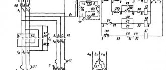
Electrical circuit diagram of a screw-cutting lathe 16K20
The electrical circuit diagram of the 16K20 screw-cutting lathe is shown in the following figure:
You can download a free electrical circuit diagram of a 16K20 screw-cutting lathe with specifications and in excellent quality from the link below:
16K20 screw-cutting lathe is shown in the following figure:
You can download this version of the electrical circuit diagram of a 16K20 screw-cutting lathe for free with specifications and in excellent quality from the link below:
Repair of screw-cutting lathe 16K20
Below are links to three albums dedicated to the repair of a 16K20 screw-cutting lathe . This documentation was developed by the State Design and Technological Institute for Modernization and Automation, Repair of Metal-Cutting Machine Tools and Maintenance of Metalworking Equipment with Software Control - GPKTI STANCOSERVICE.
Content
- General description of the machine
- Purpose and brief technical characteristics
- Controls
- Specification of main components
- Basic parameters of gears, worms, screws, nuts, racks
- Kinematic diagram
- Specification of rolling bearings
- Machine lubrication
- Lubrication map
- Description of the electrical circuit
- Electrical circuit diagram
- Machine electrical equipment specification
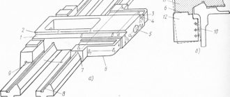
- Drawings of machine components
- Bed 16K20.010.001; 16K20.011.001; 16K20.012.001; 16K20.016.001
- Spindle head 16K20.020.001
- Tailstock 16B20.030.001; 16B20P.030.001
- Four-position tool holder 16K20.041.001
- Carriage and support 16K20.040.001 and 16K20.050.001
- Apron 16B20P.061.000
- Feed box 16B20P.070.000
- Gearbox 16K20.080.001
Download for free “Repair of screw-cutting lathe 16K20. Album 1. General description" in normal quality (70 pages) can be found at the link below:
Contents “Repair of screw-cutting lathe 16K20. Album 2. Technological process of major repairs"
- Route of a 16K20 screw-cutting lathe during a major overhaul
- List of equipment used during major repairs of the machine
- Route technological process of disassembling the machine into units
- Recommendations for defect detection and restoration of parts
- Route technological processes for parts repair
- Requirements for the quality of machine assembly
- Route technological process for assembling machine components
- Route technological process of assembly and debugging of the machine
- Testing the machine after a major overhaul
- Protocol for checking the machine for rigidity and accuracy according to GOST 18097-72
- Noise Level Standards and Test Methods
- Applications
Download for free “Repair of screw-cutting lathe 16K20. Album 2. Technological process of major repairs" in good quality (100 pages) can be found at the link below:
Contents “Repair of screw-cutting lathe 16K20. Album 3. Replaceable parts"
- Temporary norms for the consumption of replaceable parts when repairing a 16K20 machine
- Working drawings of replacement parts
Download for free “Repair of screw-cutting lathe 16K20. Album 3. Replaceable parts" in good quality (196 pages) can be found at the link below:
RAM
II.4. Locking devices. When the casing of replaceable gears or the spindle guard is opened, the travel switches S9 or S 10 are respectively triggered, turning off the main drive electric motor.
To control the treatment of the spindle, the machine has two handles located at the headstock and on the carriage. Each handle has three fixed positions: a) clockwise rotation; b) neutral position; c) counterclockwise rotation. Depending on the chosen place of work, you can only use one of them. If two handles are turned on simultaneously, an emergency shutdown of the machine will occur. The rotation of the main drive can only be resumed with the guard closed and the two handles in the neutral position by pressing the “Start hydraulic station” button.
To avoid spindle scuffing due to lack of pressure in the hydrostatic bearings, a rotation control relay 4 is installed on the machine, which delays the shutdown of the hydraulic drive until the spindle stops completely rotating.
When the spindle is overloaded with an axial load and a bending moment when the pressure of the oil entering the spindle hydrostatic bearings drops, for example, due to clogged filters, the electric contact pressure gauge turns off the rotation of the spindle.
A UІІС-2 type safety light-signal device is installed in the control cabinet, which, when the cabinet door is open, indicates: a) the switched state of the PI switch is on - alternating flashing red light of all lamps; b) the FI switch is off - the lamp does not glow; c) contact closure in the off state of the FI switch - flashing light of one, two or three lamps.
II.5. Instructions for initial start-up of the machine.
During the initial start-up of the machine, it is necessary to check the reliability of grounding and the quality of installation of electrical equipment by external inspection and measuring resistance. After the inspection, disconnect the power wires of all electric motors at the terminal sets in the control garden and, using the input circuit breaker FI, connect the machine to the workshop network. Check the operation of all locking devices. Using manual controls, check the clear operation of the relay contactor equipment. Once smooth operation of all devices located in the control cabinet is achieved, connect the previously disconnected wires to the sets of clamps. By turning on the electric motors one by one, check the direction of their rotation and begin testing the machine in operation.
II.6. Description of the electrical circuit.
When you press the button S 5,I “Start the hydraulic station” located on the spindle head, relay K3 is activated (if both handles are in the neutral position), which in turn triggers the starter K2. The electric motor of the M2 hydraulic station turns on. When the required pressure is reached (see the arrow of the pressure gauge mounted on the headstock), the main drive is turned on. By pressing the S5.2 “Hydraulic power station” button, the rotation of the main drive immediately stops. Simultaneous activation of two handles is equivalent to pressing the button S5.2 “Hydraulic station stop”.
The electric motor for rapid movement of the carriage and support M4 is controlled by pressing the jog button S8, regardless of the state of the hydraulic station. The electric cooling pump is switched on and off using switch S 12. The electric pump operates only when the main drive rotates. When the machine spindle rotates, relay K7 is activated, which charges capacitors C19...c28 and turns on the time relay KI. With its contact with a time delay for opening, the time relay set to 5 seconds prepares the activation circuit for the electromagnetic brake clutch УІ. At the moment the spindle stops (the control handle is in the neutral position), relay K7 is turned off, its contact K7 (48-52) is closed and the electromagnetic brake clutch is turned on, which will be energized for 5 seconds until the machine spindle comes to a complete stop, then turns off (because .contact K1 (50-52) opens).
When the battery is completely discharged, the spindle will automatically release. Protection against short circuit currents is provided by automatic switches and fuses. Protection of electric motors from long-term overloads is carried out by thermal relays. The types, values of rated currents, and setting currents for all mentioned devices are given in the list of elements I6K2OBФІ.000,000 pe3.2. Zero protection of the electrical equipment of the machine, which ensures the possibility of spontaneous switching on of the devices when the power supply is restored after a sudden loss, is carried out by coils of magnetic starters, which, when the voltage is below 85% of the rated value, automatically disconnect the electric motors from the network.
II.7. Recommendations for servicing electrical equipment.
II.7.I. It is necessary to periodically check the condition of the starting and relay equipment. All parts of electrical devices must be cleaned from bullets and dirt. If carbon deposits form on the contacts, the latter must be removed using a velvet file or glass paper. To avoid rust, the interface between the core and the starter armature must be periodically lubricated with machine oil, followed by obligatory wiping with a dry cloth (to prevent the armature from sticking to the core). When inspecting relay equipment, special attention should be paid to the reliability of the closing and opening of contact bridges.
II.7.2. The frequency of technical inspections of electric motors is established depending on production conditions, but not less than once every two months. During technical inspections, the condition of the input wires of the stator winding is checked, the motors are cleaned of contamination, and the reliability of grounding and shaft connection with a natural mechanism is monitored. The frequency of preventative repairs is set depending on production conditions, but at least once a year. During preventive maintenance, electric motors must be disassembled, internal and external surfaces must be cleaned, and bearing grease must be replaced. Under normal operating conditions, bearing grease should be replaced after 4000 hours of operation, and more often when operating the electric motor in a dusty and humid environment (as necessary).
II.4. Locking devices. When the casing of replaceable gears or the spindle guard is opened, the travel switches S9 or S 10 are respectively triggered, turning off the main drive electric motor.
To control the treatment of the spindle, the machine has two handles located at the headstock and on the carriage. Each handle has three fixed positions: a) clockwise rotation; b) neutral position; c) counterclockwise rotation. Depending on the chosen place of work, you can only use one of them. If two handles are turned on simultaneously, an emergency shutdown of the machine will occur. The rotation of the main drive can only be resumed with the guard closed and the two handles in the neutral position by pressing the “Start hydraulic station” button.
To avoid spindle scuffing due to lack of pressure in the hydrostatic bearings, a rotation control relay 4 is installed on the machine, which delays the shutdown of the hydraulic drive until the spindle stops completely rotating.
When the spindle is overloaded with an axial load and a bending moment when the pressure of the oil entering the spindle hydrostatic bearings drops, for example, due to clogged filters, the electric contact pressure gauge turns off the rotation of the spindle.
A UІІС-2 type safety light-signal device is installed in the control cabinet, which, when the cabinet door is open, indicates: a) the switched state of the PI switch is on - alternating flashing red light of all lamps; b) the FI switch is off - the lamp does not glow; c) contact closure in the off state of the FI switch - flashing light of one, two or three lamps.
II.5. Instructions for initial start-up of the machine.
During the initial start-up of the machine, it is necessary to check the reliability of grounding and the quality of installation of electrical equipment by external inspection and measuring resistance. After the inspection, disconnect the power wires of all electric motors at the terminal sets in the control garden and, using the input circuit breaker FI, connect the machine to the workshop network. Check the operation of all locking devices. Using manual controls, check the clear operation of the relay contactor equipment. Once smooth operation of all devices located in the control cabinet is achieved, connect the previously disconnected wires to the sets of clamps. By turning on the electric motors one by one, check the direction of their rotation and begin testing the machine in operation.
II.6. Description of the electrical circuit.
When you press the button S 5,I “Start the hydraulic station” located on the spindle head, relay K3 is activated (if both handles are in the neutral position), which in turn triggers the starter K2. The electric motor of the M2 hydraulic station turns on. When the required pressure is reached (see the arrow of the pressure gauge mounted on the headstock), the main drive is turned on. By pressing the S5.2 “Hydraulic power station” button, the rotation of the main drive immediately stops. Simultaneous activation of two handles is equivalent to pressing the button S5.2 “Hydraulic station stop”.
The electric motor for rapid movement of the carriage and support M4 is controlled by pressing the jog button S8, regardless of the state of the hydraulic station. The electric cooling pump is switched on and off using switch S 12. The electric pump operates only when the main drive rotates. When the machine spindle rotates, relay K7 is activated, which charges capacitors C19...c28 and turns on the time relay KI. With its contact with a time delay for opening, the time relay set to 5 seconds prepares the activation circuit for the electromagnetic brake clutch УІ. At the moment the spindle stops (the control handle is in the neutral position), relay K7 is turned off, its contact K7 (48-52) is closed and the electromagnetic brake clutch is turned on, which will be energized for 5 seconds until the machine spindle comes to a complete stop, then turns off (because .contact K1 (50-52) opens).
When the battery is completely discharged, the spindle will automatically release. Protection against short circuit currents is provided by automatic switches and fuses. Protection of electric motors from long-term overloads is carried out by thermal relays. The types, values of rated currents, and setting currents for all mentioned devices are given in the list of elements I6K2OBФІ.000,000 pe3.2. Zero protection of the electrical equipment of the machine, which ensures the possibility of spontaneous switching on of the devices when the power supply is restored after a sudden loss, is carried out by coils of magnetic starters, which, when the voltage is below 85% of the rated value, automatically disconnect the electric motors from the network.
II.7. Recommendations for servicing electrical equipment.
II.7.I. It is necessary to periodically check the condition of the starting and relay equipment. All parts of electrical devices must be cleaned from bullets and dirt. If carbon deposits form on the contacts, the latter must be removed using a velvet file or glass paper. To avoid rust, the interface between the core and the starter armature must be periodically lubricated with machine oil, followed by obligatory wiping with a dry cloth (to prevent the armature from sticking to the core). When inspecting relay equipment, special attention should be paid to the reliability of the closing and opening of contact bridges.
II.7.2.
The frequency of technical inspections of electric motors is established depending on production conditions, but not less than once every two months. During technical inspections, the condition of the input wires of the stator winding is checked, the motors are cleaned of contamination, and the reliability of grounding and shaft connection with a natural mechanism is monitored. The frequency of preventative repairs is set depending on production conditions, but at least once a year. During preventive maintenance, electric motors must be disassembled, internal and external surfaces must be cleaned, and bearing grease must be replaced. Under normal operating conditions, bearing grease should be replaced after 4000 hours of operation, and more often when operating the electric motor in a dusty and humid environment (as necessary). To home page