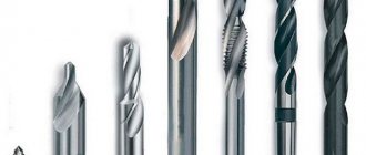
Parts, elements and geometric parameters of a twist drill
Twist drills are the most common.
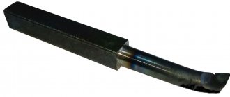
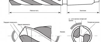
This drill (Fig. 309) consists of a working part, including a cutting part, a neck, a conical (Fig. 309, a) or cylindrical (Fig. 309, b) shank for fastening the drill in the machine spindle, a foot that serves as a stop for knocking out the drill from the spindle socket. The cutting part (Fig. 309, c) consists of two teeth formed by two grooves for removing chips; core - the middle part of the drill connecting both teeth; two front surfaces along which chips run and which absorb the cutting force; two ribbons - narrow strips along the outer diameter of the drill, serving to guide and center it in the hole; two main cutting blades formed by the intersection of the front and rear surfaces and performing the main cutting work; a transverse blade or bridge formed by the intersection of both rear surfaces. Rice. 309. Elements, geometric parameters and sharpening of spiral drills: 1 and 10 - ribbon blades; 2 and 6 — ribbons; 3 - two cutting blades; 4 and 8 — backs at the teeth; 5 - grooves; 7 - transverse blade; 9 - front surface.
A twist drill contains five blades: two main, two auxiliary (along the ribbons) and a transverse one, which does not cut, but crushes and squeezes out the metal. The cross blade of the drill has its main defect. The geometric parameters of the drill are considered on its cutting part.
The rear angle α is considered in the plane AA, parallel to the axis of the drill (Fig. 309, d), for the current point x (see section AA); it changes from αmin at the peripheral point of the drill to αmax, at the drill bridge.
The front angle γ is taken in the plane BB, perpendicular to the cutting blade of the drill (Fig. 309, d) for the current point x; this angle changes from γmin at the drill bridge to γmax at the peripheral point of the drill. The angle at the tip of the drill 2φ is between the main cutting blades: 2φ = 116 ÷ 118° when processing steel, cast iron, hard bronze; 2φ = 140° when processing aluminum and light alloys; 2φ = 80 ÷ 90° when processing ebonite, celluloid, marble.
The angle of inclination of the transverse blade ψ is 55º.
Drill sharpening. By sharpening the drill (Fig. 309, d) the following angle values are given: α min ≈ 7º, α max ≈ 26º, γ min ≈ 3º, γ max ≈ 30º.
The criterion for correct sharpening is compliance with the angles 2φ, ψ and α min.
In addition, it is necessary that the axis of the drill passes through the middle of the jumper and divides the apex angle of 2φ into two equal parts and that the main cutting blades are equal. To avoid pinching the drill on the drill, give a reverse cone towards the shank by an amount of approximately 0.05 mm per 100 mm length.
In Fig. 309, d single sharpening of the drill is given; in Fig. 309, e - double sharpening of the drill; in Fig. 309, g - single sharpening with sharpening of the transverse blade; in Fig. 309, h - single sharpening of the drill with sharpening of the ribbons. Double sharpening of the drill increases the durability of the drills, sharpening the jumper and ribbons facilitates the drilling process, reduces friction, and reduces the amount of feed force. With double sharpening there are angles 2φ and 2φ0; at 2φ = 116 - 118º, 2φ0 = 70 - 75°.
A bridgeless twist drill was proposed by the innovator V.I. Zhirov. Such drills are obtained from standard drills by using their special sharpening.
In the transverse blade (Fig. 310, c), the drills cut a groove with a grinding wheel, which significantly reduces the feed force.
Rice. 310. Bridgeless spiral drill designed by V.I. Zhirov.
Read also: GOST for gears and gears
However, the best results (increased productivity and increased durability) are provided by a combined sharpening of the transverse drill blade (Fig. 310, b). Here, at a distance K equal to one third of the length of the cutting blade, the transverse blade is sharpened with an undercut of its core at an angle of 30°. The width of the cut groove a and the depth h are equal to 0.15 of the drill diameter.
It is necessary to ensure that sharpening is done efficiently. It is especially recommended to take drills with a double cone (Fig. 310, a).
Fig.21. Parts and elements of a twist drill.
1 – working part; 2 – cutting part; 3 – guide part; 4 – neck;
5 – shank; 6 – foot
The cutting part is the part of the drill sharpened to a cone. The working part is the part of the drill equipped with two spiral grooves. The guide part is the part of the drill that ensures the direction of the drill during the cutting process. The shank is the part of the drill that serves to secure the drill.
Fig.22. Main elements of the working part of the drill
1 – front surface; 2 – back surface; 3 – cutting edge;
4 – ribbon; 5 – transverse edge
The rake surface is the helical surface of the groove along which chips flow. Rear surface - the surface facing the cutting surface. Cutting edge - the line formed by the intersection of the front and rear surfaces; The drill has two cutting edges. Ribbon - a narrow strip on the cylindrical surface of the drill, located along the screw groove; Provides direction to the drill when cutting. Cross edge is a line formed by the intersection of both back surfaces.
Geometry of a twist drill.
The geometric parameters of the twist drill are shown in Fig. 23.
Fig.23. Geometry of a twist drill.
The angle 2φ (twice the entering angle) between the cutting edges varies widely depending on the material being processed. The inclination angle of the helical groove ω determines the rake angle and ranges from 100 to 45° depending on the material being processed.
Angle ψ – the angle of inclination of the transverse cutting edge is measured between the projections of the transverse and main cutting edges onto a plane perpendicular to the axis of the drill.
To determine the geometric parameters of the cutting edges, they are considered
1) in plane NN, perpendicular to the cutting edge;
2) in the OO plane, parallel to the drill axis. The front angle γ is considered in the NN plane.
The inclination angle of the helical groove ω and the clearance angle α are considered in
Cutting elements when drilling.
The cutting speed when drilling is the peripheral speed of rotation of the point of the cutting edge most distant from the axis of the drill.
Feed when drilling is the movement of the drill along the axis in one revolution. The feed rate is measured in millimeters per revolution
drill and is designated S mm/rev. Because the drill has two main cutting edges,
then the feed per each of them is Sz = S/2.
As with turning, feed can also be measured in mm. in 1 min. (minute feed)
Fig.24. Cutting elements when drilling.
a – cut thickness in mm, measured in the direction perpendicular to the cutting edge;
b – cutting width in mm, measured along the cutting edge;
t – depth of cut – distance from the machined surface of the hole to the axis of the drill t = D/2.
Milling.
Milling is one of the highly productive and widespread methods of metal cutting.
A cutter is a tool that has several teeth, each of which can be considered a cutter.
Fig. 25 Cutting part of the cutter.
When milling, the main (rotational) movement is carried out by the cutter, and the feed movement is carried out by the workpiece. Milling is used to process planes, grooves, shaped surfaces, and cut metals.
Geometry of cutters.
| Fig. 26 Geometry of the cutting part of the cutter. |
The cutter consists of a body (body) and cutting teeth. It is a multi-tooth cutting tool in the form of a body of rotation, on the forming surface or at the end of which cutting edges are located. There are angles of the main cutting edge of the tooth in a plane normal to the cutting lump, and angles in a plane normal to the axis of the cutter.
In the plane A-A, normal to the cutting edge, there are the main rake angle y and the normal rear angle αn. In the plane B-B, normal to the cutter axis, there are the main clearance angle α and the transverse or radial clearance angle γ'.
Read also: The pressure in the hydraulic accumulator is 100 liters when cold
The main purpose of the rake angle γ is to reduce the work of plastic deformation and the work of friction along the rake surface during the cutting process and ensure the best durability of the cutting tool.
The main relief angle α is measured in the B-B plane, perpendicular to the cutter axis.
Rear Angle Purpose:
1. in creating conditions for unhindered movement of the rear surface of the tooth relative to the cutting surface;
2. in reducing the work of friction on the back surface of the tooth.
This page was last modified: 2016-08-01; Page copyright infringement
Drill
- a cutting tool designed for drilling holes in various materials.
Drills can also be used for drilling
, that is, enlarging existing, pre-drilled holes, and
drilling
, that is, obtaining blind recesses.
Classification of drills [edit | edit code ]
According to the design of the working part
there are:
- Spiral (screw)
drills are the most common drills, with a drill diameter from 0.1 to 80 mm and a working part length of up to 275 mm, widely used for drilling various materials.
- Zhirov’s designs
- on the cutting part there are three cones with angles at the apex: 2φ=116...118°; 2φ=70°; 2φ ' =55°. This increases the length of the cutting edge and improves heat dissipation conditions. A groove 0.15D wide and deep is cut into the jumper. The jumper is sharpened at an angle of 25° to the axis of the drill in a section of 1/3 of the length of the cutting edge. As a result, a positive angle γ≈5° is formed.
- Flat
(
feather
; jargon:
perki
) - used when drilling holes of large diameters and depths. The cutting part has the form of a plate (blade), which is mounted in a holder or boring bar or is integral with the shank. - Forstner drills
are an improved version of a feather drill, with additional cutters. - For deep drilling (L≥5D)
- elongated screw drills with two screw channels for internal coolant supply. Screw channels pass through the body of the drill or through tubes soldered into grooves milled into the back of the drill. - The designs of Yudovin and Masarnovsky
are distinguished by a large angle of inclination and the shape of the helical groove (ω=50...65°). There is no need to frequently remove the drill from the hole to remove chips, thereby increasing productivity. - Single-sided cutting
- used to make precise holes due to the presence of a guide (support) surface (the cutting edges are located on one side of the drill axis). - Cannon blades
are a rod whose front end is cut in half and forms a channel for removing chips. To guide the drill, a hole must first be drilled to a depth of 0.5...0.8D. - Gun
- used for drilling deep holes. They are made from a tube, which, when crimped, produces a straight groove for removing chips with an angle of 110...120° and a cavity for supplying coolant. - Hollow
(also annular, core) - drills that turn only a narrow annular part of the material into chips. - Centering
- used for drilling center holes in parts. - Stepped
- for drilling holes of different diameters in sheet materials with one drill. - with cylindrical shank (GOST 10902-77, DIN 338)
- with tapered shank (GOST 10903-77 (Morse taper), DIN 345)
- with three-, four- and hexagonal shank
- SDS, SDS+, etc.
By manufacturing method
there are:
- Solid
- spiral drills made of high-speed steel grades R9, R18, R9K15, R6M5, R6M5K5, or carbide. - Welded
- twist drills with a diameter of more than 20 mm are often made welded (the tail part is made of carbon and the working part is made of high-speed steel). - Equipped with carbide inserts
- available with straight, oblique and helical grooves (including ω=60° for deep drilling). - With replaceable carbide inserts
- also called cased (the mandrel to which the inserts are attached is called the body). Mainly used for drilling holes of 12 mm or more. - With replaceable carbide heads
- an alternative to case drills.
Read also: How to unscrew a rusty bolt
By purpose [edit | edit code ]
According to the shape of the holes being machined
there are:
According to the processed material
there are:
- Universal
- For processing metals and alloys
- For processing concrete, brick, stone
- it has a carbide tip designed for drilling hard materials (brick, concrete) with rotary impact drilling. Drills designed for a conventional drill have a cylindrical shank. The drill shank for rotary hammers has different configurations: cylindrical shank, SDS-plus, SDS-top, SDS-max, etc. - For processing glass, ceramics
- For wood processing
Color matters
Even by the appearance of the drill, you can determine its properties and qualities.
“Golden” drills are considered the most durable.
To make the right choice, ideally you need to study the markings of each drill. It informs you exactly what material it is made of and for what purposes it is suitable. Understanding labeling is not so easy, if only because there are Russian and foreign systems. But if you are interested, let me know in the comments, we will write about that too.
Source
Elements of a twist drill [edit | edit code ]
A twist drill is a cylindrical rod, the working part of which is equipped with two (less often four) helical spiral grooves designed to remove chips and form cutting elements - ribbons.
- Working part
- The cutting part
has two main cutting edges formed by the intersection of the front helical surfaces of the grooves along which chips flow with the rear surfaces, as well as a transverse cutting edge (jumper) formed by the intersection of the rear surfaces. - The guide part
has two auxiliary cutting edges formed by the intersection of the front surfaces with the surface
of the strip
(a narrow strip on the cylindrical surface of the drill, located along the helical groove and ensuring the direction of the drill during cutting, as well as reducing friction of the side surface against the walls of the hole).
- for securing the drill to a machine or hand tool.
for transmitting torque to the drill or
a foot
for knocking the drill out of the conical socket.
, which ensures the exit of the wheel when grinding the working part of the drill.
Drill angles [ edit | edit code ]
- Point angle 2φ
is the angle between the main cutting edges of the drill. As 2φ decreases, the length of the cutting edge of the drill increases, which leads to improved heat dissipation conditions and, thus, increased durability of the drill. But with a small 2φ, the strength of the drill decreases, so its value depends on the material being processed. For soft metals 2φ=80…90°. For steels and cast irons 2φ=116…118°. For very hard metals 2φ=130…140°. - The angle of inclination of the helical groove ω
is the angle between the axis of the drill and the tangent to the helical line of the ribbon. The greater the inclination of the grooves, the better the removal of chips, but the less rigidity of the drill and the strength of the cutting edges, since the volume of the groove increases along the length of the working part of the drill. The value of the inclination angle depends on the material being processed and the diameter of the drill (the smaller the diameter, the smaller ω). - The rake angle γ
is determined in a plane perpendicular to the cutting edge, and its value changes. It has the greatest value at the outer surface of the drill, the smallest at the transverse edge. - The clearance angle α
is determined in a plane parallel to the drill axis. Its values, like the front angle, change. Only it has the greatest value at the transverse edge, and the smallest at the outer surface of the drill. - The inclination angle of the transverse edge ψ
is located between the projections of the main and transverse cutting edges onto a plane perpendicular to the drill axis. For standard drills ψ=50…55°.
Variable values of the angles γ and α create unequal cutting conditions at different points of the cutting edge.
Drill angles during cutting [edit | edit code ]
The angles of the drill during the cutting process differ from the angles in the static state, just like those of the cutters. The cutting plane in kinematics turns out to be rotated relative to the cutting plane in statics by an angle μ, and the actual angles during the cutting process will be as follows:
Select Shank
Drills are used in tools such as screwdrivers, drills and hammer drills. To securely secure the drill, pay attention to the type of chuck of your tool. This will determine what kind of drill shank you need.
Cylindrical. The most popular type, just a cylinder without any tricks. Clamps perfectly into drill and screwdriver chucks.
SDS. If you plan to use a hammer drill, you will need an SDS drill - that’s what people call it: “for a hammer drill.” There are several types of SDS systems (Plus, Max, Top and others). Just check in the documentation for your tool which one is installed in your hammer drill.
Which manufacturers can you trust?
The quality and service life of metal processing drills depends on the manufacturer. Craftsmen who use drills every day claim that good tools can be found both from domestic and foreign companies. Russian-made drills are wear-resistant, strong and durable, but, unfortunately, there are fewer and fewer of them on the market every year. Now products and “Zubr” are in demand. These brands produce inexpensive but reliable high-quality instruments. Drills and “ATTACK” have also proven themselves well. Among imported ones, professionals prefer metal cutting tools, Bosch, Haisser and Makita. Their characteristics are approximately the same: they can withstand extreme loads, work “for wear”, and wear occurs slowly. Good value for money. There are two more and Dewalt. Their products differ from others in their high drilling speed. The price of a tool depends on the country of manufacture, length, diameter, strength and what it is intended for.
| Rating of the best drills for metal processing |
| Bosch 2607017154 |
| Attack N802-6 |
| Wurth Zebra Spiralbohrersatz HSS |
| Anchor 25219 |
| Metabo Bestell-Nr. 27 094 HSS-G |
| AEG HSS-G 4932430416 |
| Bison MET-SH H19 R6M5 |
| DeWALT DT7926 Extreme2 HSS |
| Hawera HSS-C Spiral Bohrer GQ-32692 |
| Irwin TurboMax 10503992 |
Choices.
To drill metal, choose appropriate drills at prices ranging from 55 to 4,800 rubles per set. Cheap metal drills should be treated with distrust - the chance that they are made of cheap low-quality steel is quite high.
If you make furniture, you will probably need Forstner drills of various diameters. They cost from 400 to 800 rubles apiece.
To drill holes in brick and concrete walls, you need pobedit drills, and here it is better to give preference to a trusted manufacturer. They will cost 110-1250 rubles.
If you need to drill a hole in tiles, glass or a mirror, buy specialized glass/tile drills. They cost from 350 rubles.
Source
ALPHABETIC INDEX OF TERMS IN ENGLISH
| axis | 1.1 |
| back taper | 1.32 |
| bevel | 2.7.1, 2.14.3 |
| body | 1.5 |
| body clearance | 1.17 |
| body clearance diameter | 1.31 |
| bore | 2.14.1 |
| chisel edge | 1.26 |
| chisel edge angle | 1.44 |
| chisel edge corner | 1.27 |
| chisel edge length | 1.28 |
| countershink angle | 2.9.2 |
| depth of body clearance | 1.18 |
| drill diameter | 1.30 |
| driving slot | 2.14.2 |
| face | 1.22 |
| flank (major flank) | 1.21 |
| flute | 1.9 |
| fluted land | 1.10 |
| flute length | 1.8 |
| heel | 1.19 |
| helix angle | 1.38 |
| land | 1.14 |
| lead of helix | 1.37 |
| leading edge of the land (minor cutting edge) | 1.16 |
| left-hand cutting drill | 1.36 |
| major cutting edge (lip) | 1.23 |
| major cutting edge (lip) length | 1.29 |
| normal clearance of the major cutting edge | 1.43 |
| normal rake | 1.40 |
| outer corner | 1.25 |
| overall length | 1.7 |
| parallel shank | 1.2.2 |
| parallel shank with tenon drive | 1.2.3 |
| pilot | 2.9.2 |
| point angle | 1.41 |
| point (cutting part) | 1.20 |
| protection angle | 2.10.1 |
| recess | 1.6 |
| right-hand cutting drill | 1.35 |
| rotation of cutting | 1.34 |
| shank | 1.2 |
| side clearance of the major cutting edge | 1.42 |
| side rake | 1.39 |
| subland diameter | 2.12.1 |
| tang | 1.3 |
| tenon | 1.4 |
| taper shank | 1.21 |
| web | 1.12 |
| web taper | 1.23 |
| web thickness | 1.13 |
| wedge | 1.24 |
| width of fluted land | 1.11 |
| width of land | 1.15 |
ALPHABETICAL INDEX OF TERMS IN GERMAN
| Achse | 1.1 |
| Anschnitt | 2.7.1, 2.14.3 |
| Austreiblappen | 1.3 |
| Bohrerdurchmesser | 1.30 |
| Bohrung | 2.14.1 |
| Drallsteigung | 1.37 |
| Drallwinkel | 1.38 |
| Einstich | 1.6 |
| Phase | 1.14 |
| Fasenbreite | 1.15 |
| 2.9.2 | |
| 1.7 | |
| 1.21 | |
| Hauptschneide | 1.23 |
| 1.29 | |
| Kegelschaft | 1.2.1 |
| Kern | 1.12 |
| Kerndicke | 1.13 |
| Kerndickenzunahme | 1.33 |
| 1.5 | |
| Linksshneidender Spiralbohrer | 1.36 |
| Mehrfasen-Stufenbohrer mit Zylinderschaft | 2.12 |
| Mitnehmerlappen | 1.4 |
| Nebenschneide | 1.16 |
| Normal-Freiwinkel | 1.43 |
| Normal-Spanwinkel | 1.40 |
| Quernut | 2.14.2 |
| Querschneide | 1.26 |
| Querschneidenecke | 1.27 |
| 1.28 | |
| Querschneidenwinkel | 1.44 |
| Rechtsschneidender Spiralbohrer | 1.35 |
| 1.17 | |
| 1.31 | |
| 1.19 | |
| 1.18 | |
| Schaft | 1.2 |
| Schneidenecke | 1.25 |
| Schneidkeil | 1.24 |
| Schneidrichtung | 1.34 |
| Seiten-Freiwinkel | 1.42 |
| Seiten-Spanwinkel | 1.39 |
| Senkwinkel | 2.9.1 |
| 1.22 | |
| Spannut | 1.9 |
| 1.8 | |
| Spitze | 1.20 |
| Spitzenwinkel | 1.41 |
| Steg | 1.10 |
| Stegbreite | 1.11 |
| Stufendurchmesser | 2.12.1 |
| 1.32 | |
| Zylinderschaft | 1.2.2 |
| Zylinderschaft mit Mitnehmerlappen | 1.2.3 |
| Winkel der Schutzsenkung | 2.10.1 |
ALPHABETICAL INDEX OF TERMS IN FRENCH
| 2.14.1 | |
| 1.12 | |
| angle au sommet | 1.41 |
| angle de coupe | 1.39 |
| angle de coupe normal | 1.40 |
| angle | 1.38 |
| angle de centrale | 1.44 |
| angle du foret | 2.91 |
| angle du chanfrein de protection | 2.10.1 |
| centrale | 1.26 |
| principale | 1.23 |
| 1.1 | |
| beс | 1.25 |
| bord d'attaque du listel (secondaire) | 1.16 |
| chanfrein | 2.7.1, 2.14.3 |
| (longitudinal) | 1.32 |
| 1.33 | |
| corps | 1.5 |
| 1.17 | |
| de principale | 1.42 |
| normale de principale | 1.43 |
| de | 1.31 |
| de percage | 2.12.1 |
| du foret | 1.30 |
| de | 1.13 |
| face de coupe | 1.22 |
| face de (face de principale) | 1.21 |
| foret coupe droite | 1.35 |
| foret coupe gauche | 1.36 |
| gorge | 1.6 |
| corps | 1.5 |
| goujure | 1.9 |
| largeur de | 1.11 |
| large-scale listel | 1.15 |
| 1.10 | |
| listel | 1.14 |
| logement de tenon | 2.14.2 |
| longueur de centrale | 1.28 |
| longueur de principale | 1.29 |
| longueur | 1.8 |
| longueur totale | 1.7 |
| pas | 1.37 |
| party active | 1.20 |
| pilote | 2.9.2 |
| pointe | 1.27 |
| profondeur du | 1.18 |
| gueue | 1.2 |
| gueue conique | 1.2.1 |
| queue cylindrique | 1.2.2 |
| queue cylindrique tenon | 1.2.3 |
| rotation | 1.34 |
| taillant | 1.24 |
| talon | 1.19 |
| tenon | 1.3, 1.4 |