Quality control
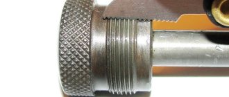
To ensure that the workpiece has been processed correctly, it is necessary to use thread templates.
With their help, the thread pitch is checked. But for a comprehensive assessment, a thread gauge is used. For convenience, it is installed in a rack and adjusted according to a standard or template, then the movement of the part itself is checked.
You can also use the simplest and most commonly used method. Take a nut or bolt and scroll it over the completed part.
If scuffing is noticeable on the thread as you move, or more effort needs to be applied, then you have made an error in your work. Now you already know how to use a lathe to make various nuts, bolts or threaded connections.
It is important to remember that such parts require great care and tenderness with each pass, and even quality control. It’s better to spend more time on work than to ruin several pieces later
How to thread a bolt and nut
The question of how to cut the thread of a bolt or nut is far from idle. During repairs, apartment and house owners are faced with the need to restore old threads of anchors, bolts, nuts, or simply threads found in metal plates.
Or you may even need to cut a new thread on the bolt or nut. For professional turners or mechanics, this task does not present any difficulties, but those who have never encountered such a process need to arm themselves with some theoretical knowledge, which is outlined in this article.
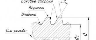
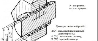
Sides of trapezoid
The paired sides of trapezoids have their own names:
- The bases of a trapezoid are the sides that are located on parallel lines.
- Lateral - sides that are not on parallel lines.
Let's illustrate this with a picture:
In this case, sides AB and CD are parallel to each other. This means that they are the foundations. But AC and BD, on the contrary, are clearly not parallel. And accordingly, these are the sides.
By the way, the location of the sides does not depend on the location of the figure itself. Even in such situations
anyway, parallel sides will be considered bases, and non-parallel sides will be considered lateral.
Features of multi-start thread
To provide the screw with strength characteristics and increase its stroke, multi-start trapezoidal threads are used. In this case, all parameters, such as the height of the thread, its diameter, are absolutely the same, with a single-start appearance. The only difference is the number of moves per step. For example, three-start threads have a stroke three times their pitch. All this can be seen in the pictures.
Let us give an example so that this type becomes clear to every person. Everyone uses regular lids for canning vegetables and fruits. To open them you need to make a minimum of effort. When using large diameter cylinders, it is much more difficult to get into the grooves of a single-thread thread. That is why multi-pass ones are used.
This type of carving can be determined visually, just look at the drawing.
You can see exactly how many turns go from the beginning of the screw. Multi-pass threads are manufactured using complex technologies and, accordingly, are more expensive.
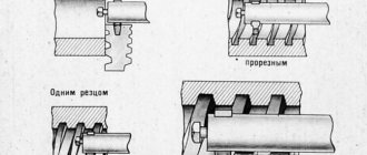
Common production method
It is in production that cutting trapezoidal threads takes place in this way:
- working equipment is checked and adjusted;
- thanks to the slotted cutter, small indentations are made on the screw;
- using a narrow slotted element, the screw is cut to a certain diameter;
- with the help of a profile slotted element, the final production of trapezoidal threads is carried out;
- the finished part is checked in accordance with ready-made templates.
Multi-start thread cutting
Cutting requires compliance with certain rules on metal-cutting equipment. The operation requires precise observance of angular divisions at the moment of sequential transition from one step to another. This allows you to maintain the exact number of thread starts.
Cutting is done in the following ways:
- gradual rotation of the fixed part at a given angle in the driving chuck;
- milling the product with disk or comb cutters (processing is carried out continuously or sequentially by dividing it into component parts).
The machine is adjusted not by step, as for a single-pass design, but by stroke size. In this case, the step and stroke determine the distance that the cutter or cutter must travel during one rotation of the workpiece. For example, to cut a three-start system onto a bolt with a diameter of 20 millimeters, the pitch size should be two millimeters. On machines equipped for such operations, special provisions are provided on the gearbox. Cutting a multi-start design with the specified parameters is done by setting the gearbox control lever on the headstock to a step with indices 2x3. On other machines, the stroke value is adjusted using a special step change unit.
The obtained result allows you to determine the number of sectors and the angle through which you need to rotate the workpiece, re-fixing it in the spindle. Some machines are equipped with dividing devices to solve this problem. They allow you to accurately set the required angle. For example, to cut a three-start thread, it is turned clockwise by twenty divisions. For a four-start it is necessary to rotate 15 divisions. The greater the number of cuts required, the fewer divisions should be set.
If such a device is not provided, use the holes provided in the spindle. They allow you to change the angle starting from 30° in variable increments of 15 and 30 degrees. They correspond to the most commonly used numbers of entries from 12 to 2.
Threading techniques
It is immediately necessary to make a reservation that the rod at the end and the threaded hole in the nut must be chamfered by any available method. Chamfers are necessary for precise entry without distortion of the cutting tool, that is, the tap and die. Next, we clamp the thread cutting object into the driver, clamp the rod or workpiece under the nut from a vice and proceed to thread cutting.
Thread cutting with a die
This is done without the use of excessive force and always with a lubricant, for which sulfo-fresol is ideal. However, if this is not available, you can use an emulsion (a solution of mineral oil in water) or simply vegetable oils.
By the way, if you decide to cut the thread of a bolt made of stainless steel or copper, there is no better lubricant than ordinary lard, which has been tested more than once in practice.
When cutting a thread, you need to feel the tap or die: if they begin to spring a little, that is, resist strongly, you need to turn them out and clear them of chips. If this is neglected, the cutting tool may simply crack and you will have to prepare a new rod or blank for the nut again.
And finally: if you do not have the opportunity to order blanks for a bolt or nut from a turner, purchase round timber (rolled metal in the form of a circle), which can have a diameter of five to 20 mm, and you don’t need more, because it is almost impossible to cut large-diameter threads by hand.
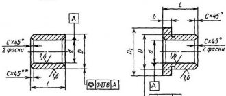
TOLERANCES
The numerical values of the tolerances for the diameters of external and internal threads must correspond to those indicated in the table. 3 – 5.
Table 3
Diameter tolerances d
and
D
1
| Step R , mm | External thread | Internal thread | Step R , mm | External thread | Internal thread | ||
| Degree of accuracy | Degree of accuracy | ||||||
| 4 | 6 | 4 | 4 | 6 | 4 | ||
| Tolerance, µm | Tolerance, µm | ||||||
| Td | Td | ||||||
| 1,5 | 150 | 236 | 190 | 16 | 710 | – | 1000 |
| 2 | 180 | 280 | 236 | 18 | 800 | – | 1120 |
| 3 | 236 | 375 | 315 | 20 | 850 | – | 1180 |
| 4 | 300 | 475 | 375 | 22 | 900 | – | 1250 |
| 5 | 335 | 530 | 450 | 24 | 950 | – | 1320 |
| 6 | 375 | 600 | 500 | 28 | 1060 | – | 1500 |
| 7 | 425 | 670 | 560 | 32 | 1120 | – | 1600 |
| 8 | 450 | 710 | 630 | 36 | 1250 | – | 1800 |
| 9 | 500 | 800 | 670 | 40 | 1320 | – | 1900 |
| 10 | 530 | 850 | 710 | 44 | 1400 | – | 2000 |
| 12 | 600 | 950 | 800 | 48 | 1500 | – | 2120 |
| 14 | 670 | – | 900 |
Table 4
Diameter tolerances d
2 and
D
2
| Nominal thread diameter d , mm | Step P , mm | External thread | Internal thread | ||||||
| Degree of accuracy | |||||||||
| 6 | 7 | 8 | 9 | 6 | 7 | 8 | 9 | ||
| Tolerance, µm | |||||||||
| St. 5.6 to 11.2 | 1,5 | 132 | 170 | 212 | 265 | 180 | 224 | 280 | 355 |
| 2 | 150 | 190 | 236 | 300 | 200 | 250 | 315 | 400 | |
| 3 | 170 | 212 | 265 | 335 | 224 | 280 | 355 | 450 | |
| St. 11.2 to 22.4 | 2 | 160 | 200 | 250 | 315 | 212 | 265 | 335 | 425 |
| 3 | 180 | 224 | 280 | 355 | 236 | 300 | 375 | 475 | |
| 4 | 212 | 265 | 335 | 425 | 280 | 355 | 450 | 560 | |
| 5 | 224 | 280 | 355 | 450 | 300 | 375 | 475 | 600 | |
| 8 | 280 | 355 | 450 | 560 | 375 | 475 | 600 | 750 | |
| St. 22.4 to 45 | 2 | 170 | 212 | 265 | 335 | 224 | 280 | 355 | 450 |
| 3 | 200 | 250 | 315 | 400 | 265 | 335 | 425 | 530 | |
| 5 | 236 | 300 | 375 | 475 | 315 | 400 | 500 | 630 | |
| 6 | 265 | 335 | 425 | 530 | 355 | 450 | 560 | 710 | |
| 7 | 280 | 355 | 450 | 560 | 375 | 475 | 600 | 750 | |
| 8 | 300 | 375 | 475 | 600 | 400 | 500 | 630 | 800 | |
| 10 | 315 | 400 | 500 | 630 | 425 | 530 | 670 | 850 | |
| 12 | 335 | 425 | 530 | 670 | 450 | 560 | 710 | 900 | |
| St. 45 to 90 | 3 | 212 | 265 | 335 | 425 | 280 | 355 | 450 | 560 |
| 4 | 236 | 300 | 375 | 475 | 315 | 400 | 500 | 630 | |
| 5 | 250 | 315 | 400 | 500 | 335 | 425 | 530 | 670 | |
| 8 | 315 | 400 | 500 | 630 | 425 | 530 | 670 | 850 | |
| 9 | 335 | 425 | 530 | 670 | 450 | 560 | 710 | 900 | |
| 10 | 335 | 425 | 530 | 670 | 450 | 560 | 710 | 900 | |
| 12 | 375 | 475 | 600 | 750 | 500 | 630 | 800 | 1000 | |
| 14 | 400 | 500 | 630 | 800 | 530 | 670 | 850 | 1060 | |
| 16 | 425 | 530 | 670 | 850 | 560 | 710 | 900 | 1120 | |
| 18 | 450 | 560 | 710 | 900 | 600 | 750 | 950 | 1180 | |
| 20 | 450 | 560 | 710 | 900 | 600 | 750 | 950 | 1180 | |
| St. 90 to 180 | 4 | 250 | 315 | 400 | 500 | 335 | 425 | 530 | 670 |
| 5 | 280 | 355 | 450 | 560 | 375 | 475 | 600 | 750 | |
| 6 | 300 | 375 | 475 | 600 | 400 | 500 | 630 | 800 | |
| 8 | 335 | 425 | 530 | 670 | 450 | 560 | 710 | 900 | |
| 12 | 400 | 500 | 630 | 800 | 530 | 670 | 850 | 1060 | |
| 14 | 425 | 530 | 670 | 850 | 560 | 710 | 900 | 1120 | |
| 16 | 450 | 560 | 710 | 900 | 600 | 750 | 950 | 1180 | |
| 18 | 475 | 600 | 750 | 950 | 630 | 800 | 1000 | 1250 | |
| St. 90 to 180 | 20 | 475 | 600 | 750 | 950 | 630 | 800 | 1000 | 1250 |
| 22 | 500 | 630 | 800 | 1000 | 670 | 850 | 1060 | 1320 | |
| 24 | 530 | 670 | 850 | 1060 | 710 | 900 | 1120 | 1400 | |
| 28 | 560 | 710 | 900 | 1120 | 750 | 950 | 1180 | 1500 | |
| 32 | 600 | 750 | 950 | 1180 | 800 | 1000 | 1250 | 1600 | |
| St. 180 to 355 | 8 | 355 | 450 | 560 | 710 | 475 | 600 | 750 | 950 |
| 10 | 400 | 500 | 630 | 800 | 530 | 670 | 850 | 1060 | |
| 12 | 425 | 530 | 670 | 850 | 560 | 710 | 900 | 1120 | |
| 18 | 500 | 630 | 800 | 1000 | 670 | 850 | 1060 | 1320 | |
| 20 | 530 | 670 | 850 | 1060 | 710 | 900 | 1120 | 1400 | |
| 22 | 530 | 670 | 850 | 1060 | 710 | 900 | 1120 | 1400 | |
| 24 | 560 | 710 | 900 | 1120 | 750 | 950 | 1180 | 1500 | |
| 32 | 530 | 800 | 1000 | 1250 | 850 | 1060 | 1320 | 1700 | |
| 36 | 670 | 850 | 1060 | 1320 | 900 | 1120 | 1400 | 1800 | |
| 40 | 670 | 850 | 1060 | 1320 | 900 | 1120 | 1400 | 1800 | |
| 44 | 710 | 900 | 1120 | 1400 | 950 | 1180 | 1500 | 1900 | |
| 48 | 750 | 950 | 1180 | 1500 | 1000 | 1250 | 1600 | 2000 | |
| St. 355 to 640 | 12 | 450 | 560 | 710 | 900 | 600 | 750 | 950 | 1180 |
| 16 | 500 | 630 | 800 | 1000 | 670 | 850 | 1060 | 1320 | |
| 20 | 560 | 710 | 900 | 1120 | 750 | 950 | 1180 | 1500 | |
| 24 | 600 | 750 | 950 | 1180 | 850 | 1060 | 1320 | 1700 | |
| 48 | 800 | 1000 | 1250 | 1600 | 1060 | 1320 | 1700 | 2120 |
Table 5
Diameter tolerances d
3
| Nominal thread diameter d , mm | Step R , mm | Main diameter deviation d 2 | ||||||
| With | e | g | ||||||
| Degree of accuracy | ||||||||
| 8 | 9 | 6 | 7 | 8 | 6 | 7 | ||
| Tolerance, µm | ||||||||
| St. 5.6 to 11.2 | 1,5 | 405 | 471 | 232 | 279 | 332 | 197 | 245 |
| 2 | 445 | 525 | 259 | 309 | 366 | 226 | 276 | |
| 3 | 501 | 589 | 298 | 350 | 416 | 261 | 313 | |
| St. 11.2 to 22.4 | 2 | 462 | 544 | 271 | 321 | 383 | 238 | 288 |
| 3 | 520 | 614 | 310 | 365 | 435 | 273 | 328 | |
| 4 | 609 | 721 | 360 | 426 | 514 | 325 | 391 | |
| 5 | 656 | 775 | 386 | 456 | 550 | 351 | 421 | |
| 8 | 828 | 965 | 482 | 576 | 695 | 435 | 529 | |
| St. 22.4 to 45 | 2 | 481 | 569 | 284 | 336 | 402 | 251 | 303 |
| 3 | 564 | 670 | 335 | 397 | 479 | 298 | 361 | |
| 5 | 681 | 806 | 401 | 481 | 575 | 366 | 446 | |
| 6 | 767 | 899 | 449 | 537 | 649 | 411 | 499 | |
| 7 | 813 | 950 | 475 | 569 | 688 | 433 | 527 | |
| 8 | 859 | 1015 | 507 | 601 | 726 | 460 | 554 | |
| 10 | 925 | 1087 | 544 | 650 | 775 | 490 | 596 | |
| 12 | 998 | 1173 | 589 | 701 | 833 | 534 | 646 | |
| St. 45 to 90 | 3 | 589 | 701 | 350 | 116 | 504 | 313 | 379 |
| 4 | 659 | 784 | 390 | 470 | 564 | 355 | 435 | |
| 5 | 712 | 837 | 419 | 500 | 606 | 384 | 465 | |
| 8 | 890 | 1052 | 526 | 632 | 757 | 479 | 585 | |
| 9 | 943 | 1118 | 559 | 671 | 803 | 509 | 621 | |
| 10 | 963 | 1138 | 569 | 681 | 813 | 515 | 627 | |
| 12 | 1085 | 1273 | 639 | 764 | 920 | 584 | 709 | |
| 14 | 1142 | 1355 | 680 | 805 | 967 | 620 | 745 | |
| 16 | 1213 | 1438 | 721 | 853 | 1028 | 661 | 793 | |
| 18 | 1288 | 1525 | 763 | 900 | 1088 | 703 | 840 | |
| 20 | 1313 | 1550 | 775 | 912 | 1100 | 708 | 845 | |
| St. 90 to 180 | 4 | 690 | 815 | 408 | 489 | 595 | 373 | 454 |
| 5 | 775 | 912 | 456 | 550 | 669 | 421 | 515 | |
| 6 | 830 | 986 | 493 | 587 | 712 | 455 | 549 | |
| 8 | 928 | 1103 | 551 | 663 | 795 | 504 | 616 | |
| 12 | 1122 | 1335 | 670 | 795 | 958 | 615 | 740 | |
| 14 | 1193 | 1418 | 711 | 843 | 1018 | 651 | 783 | |
| St. 90 to 180 | 16 | 1263 | 1500 | 753 | 890 | 1078 | 693 | 830 |
| 18 | 1338 | 1588 | 794 | 950 | 1138 | 734 | 890 | |
| 20 | 1363 | 1613 | 806 | 962 | 1150 | 739 | 895 | |
| 22 | 1450 | 1700 | 849 | 1011 | 1224 | 780 | 943 | |
| 24 | 1538 | 1800 | 899 | 1074 | 1299 | 828 | 1003 | |
| 28 | 1625 | 1900 | 950 | 1138 | 1375 | 880 | 1068 | |
| 32 | 1718 | 2005 | 1015 | 1203 | 1453 | 945 | 1133 | |
| St. 180 to 355 | 8 | 965 | 1153 | 576 | 695 | 832 | 529 | 648 |
| 10 | 1088 | 1300 | 650 | 775 | 938 | 596 | 721 | |
| 12 | 1173 | 1398 | 701 | 833 | 1008 | 646 | 778 | |
| 18 | 1400 | 1650 | 825 | 987 | 1200 | 765 | 928 | |
| 20 | 1488 | 1750 | 875 | 1050 | 1275 | 808 | 983 | |
| 22 | 1513 | 1775 | 887 | 1062 | 1287 | 818 | 993 | |
| 24 | 1600 | 1875 | 936 | 1124 | 1361 | 865 | 1053 | |
| 32 | 1780 | 2092 | 1053 | 1265 | 1515 | 983 | 1195 | |
| 36 | 1885 | 2210 | 1118 | 1343 | 1605 | 1048 | 1273 | |
| 40 | 1925 | 2250 | 1138 | 1363 | 1625 | 1063 | 1288 | |
| 44 | 2030 | 2380 | 1203 | 1440 | 1715 | 1128 | 1365 | |
| 48 | 2145 | 2545 | 1273 | 1523 | 1810 | 1188 | 1438 | |
| St. 355 to 640 | 12 | 1223 | 1460 | 733 | 870 | 1058 | 678 | 815 |
| 16 | 1375 | 1625 | 815 | 978 | 1190 | 755 | 918 | |
| 20 | 1550 | 1825 | 912 | 1100 | 1337 | 845 | 1033 | |
| 24 | 1663 | 1950 | 986 | 1174 | 1424 | 915 | 1103 | |
| 48 | 2233 | 2670 | 1335 | 1585 | 1898 | 1250 | 1500 |
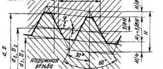
Trapezoidal thread - properties and cutting methods
The most widely used are trapezoidal threads and rectangular threads; they are used in the manufacture of various screws, such as lead screws of metal-cutting machines, press screws and various lifting devices, as well as worm gears.
If a rectangular thread has a profile in the form of a rectangle, then a trapezoidal thread has the shape of an isosceles trapezoid. This thread can have a profile angle of 15, 24, 30 and 40 degrees. During operation of the screw, natural frictional forces arise, which are caused by the presence of lubricant, surface roughness, materials from which the parts are made, as well as the profile angle. If a rectangular thread, in which the profile angle is equal to zero, will have a lower coefficient of friction, then the trapezoidal thread benefits in that its radial clearances can be determined by a fit along the average diameter, while for a rectangular thread they are determined by the outer or inner diameter.
If we compare these threads in terms of complexity of execution, then trapezoidal threads are easier to manufacture, and therefore are used much more often. Most often it is made with a profile angle of 30 °.
Trapezoidal threads have a cutting technological process that is almost similar to the production of rectangular threads. Some cutting features arise, which depend on the size of the surface finish and its accuracy.
There are several methods for cutting this type of thread.
Thread cutting with one cutter:
- the workpiece is measured and a groove is made for the cutter to exit;
- in accordance with the existing template, the finishing cutter is sharpened;
- the cutter is accurately installed and secured, and it must be on the line of centers and parallel to the axis of the thread being cut;
- setting up the machine and feeding the cutter for cutting the thread profile;
- The resulting profile is checked using a template, as well as the average thread diameter.
Thread cutting with three cutters:
- preparation of the workpiece is carried out;
- three cutters are sharpened - slotted straight, slotted narrow and profile;
- The slotted cutters are installed and secured securely. Depending on the helix angle, they are located either perpendicular to the sides of the helical groove or parallel to the thread axis and must be at the height of the center line.
In some industries, the following method has become widespread by which screws with trapezoidal threads are made:
- the equipment is being adjusted to perform this operation;
- the groove is cut to half the required depth using a slotting cutter;
- using a narrow slotted cutter, further cutting of the groove is carried out to the size of the internal diameter;
- using a profile cutter, the final cutting of the trapezoidal thread is carried out;
- The work performed is checked using a thread gauge and a template.
Thus, we examined the main methods of performing this type of carving. Now let’s take a closer look at how the work of cutting trapezoidal threads is practically carried out:
- It is necessary to prepare a workpiece for this type of work.
- Following the processing scheme, it is necessary to sharpen the profile roughing, groove and finishing cutters.
- Conduct all necessary equipment adjustments to perform this type of work.
- Using the first profile cutter, cut a trapezoidal groove to 85% of the depth.
- Process the bottom of the groove with a groove cutter.
- Carry out final cutting and cleaning of the sides of the resulting profile.
- Check the quality of the work performed using a template and gauge.
As you can see, everything is quite clear and easy to implement.
Manufacturing conditions
Compared to other types, trapezoidal threads are much easier to manufacture.
That is why it is more often used in various fields. The most popular is the trapezoidal thread screw, which has a profile angle of 30°. The production technology is very similar to that used for cutting rectangular threads. But there are still significant differences regarding the accuracy and cleanliness of manufacturing. Cutting a trapezoidal thread is no different from the same procedure with a rectangular thread. At the moment, there are several such methods.
Rectangular and trapezoidal thread cutting
Cutting threads of this profile has a number of distinctive features from cutting triangular threads. Rectangular and trapezoidal threads often have two, three, and a large number of starts, and therefore the helix angle can be significantly greater than the helix angle of triangular threads and reach values of |/>40°.
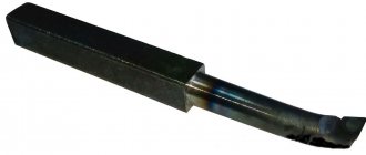
When cutting threads of rectangular and trapezoidal profiles, rod cutters are used. The shape of the cutter profile must correspond to the profile that is obtained at the intersection of the helical surface of the thread with the front surface of the cutter. The main cutting edge of the cutter must be parallel to the axis of the thread being cut. The front angle of the cutter is zero, and the back angle is 6-8°.
To ensure normal cutting conditions, it is necessary that the actual clearance angle be at least 3°. When cutting a right-hand thread, the clearance angle at the left cutting edge of the cutter should be 2° greater than the thread helix angle, and the clearance angle at the right cutting edge should be about 3°. When cutting a left-hand thread, the values of these angles are changed to the opposite.
The most common are two methods of installing a cutter when cutting threads with a helix angle of |/>4°. In the first method, the main cutting edge of the cutter is set parallel to the axis of the part (Fig. 10.11a), which allows you to cut a thread whose profile coincides with the profile of the cutter. The disadvantages of this method are the unequal operating conditions of the side cutting edges of the cutter. The cutting angle at the right side edge of the cutter is greater than 90°(-уо), which worsens the cutting conditions. To improve them, a groove is made on the front surface along this cutting edge (Fig. 10.11.6). The cutting angle at the left side edge of the cutter is less than 90°, which weakens the cutting edge and reduces its durability. As a result, the cutter has to be sharpened frequently. In addition, as the thread lead angle increases, the load on the cutter increases; it deviates to the left and down, which can lead to undercutting of the thread profile.
40°»/>
Rice. 10.11. Methods (a-c) for installing a cutter when cutting threads with a helix angle y>40°.
In the second method (Fig. 10.11, c), the main cutting edge of the cutter is set perpendicular to the helix, i.e. side surfaces of the threaded groove. In this case, both side cutting edges are in the same more favorable working conditions. The disadvantage of this method is the distortion of the thread profile, which is greater the greater the helix angle of the thread.
Taking into account the advantages and disadvantages of each method, the second method of installing the cutter is used during rough working strokes to remove large allowances. When cutting threads with a pitch of 3-4 mm, as well as when finishing working strokes (with an allowance of 0.2-0.3 mm), the first method of installing the cutter is used. The main cutting edge is set exactly on the line of the centers of the machine using a rotary head 3 (Fig. 10.12). The head is fixed in the desired position (according to mark A relative to scale B) with screw 6, which is screwed onto the rod 5 of the head along the thread with a large pitch and screwed into the body 4 of the cutters along the thread with a fine pitch. This device allows you to securely fasten the head 3 in the desired position. Cutter 1 is secured in the head with screw 2.
Rice. 10.12. Holder with rotating head for thread cutter Fig. 10.13.
A block of two cutters for cutting trapezoidal threads:
1 - trapezoidal (profile) cutter, 2 - slotted cutter
Fig. 10.14.
Chucks for cutting multi-start threads:
1,2, 3 and 4 - slots for cutting two- and four-start threads,
G, 2′ and 3′ - slots for cutting three-start threads, 5 - driving part, 6 - body,
Sometimes the cutter head is made with a slot, which allows the cutter to be pressed out slightly to improve the quality of the machined surface.
Trapezoidal threads with a pitch of more than 3-4 mm are cut in two ways. According to the first method, using a groove cutter, the width of which is 0.1-0.2 mm less than the width of the thread profile, a screw groove with an internal diameter equal to the internal diameter of the thread being cut is cut, and then the screw groove is shaped into a trapezoid (with right and left cutters), the width the base of which, according to the outer diameter of the thread, is 0.3-10.4 mm less than required. The final processing of the lateral surfaces of the thread is carried out with a cutter with a full profile. According to the second method, a profile groove is cut with a trapezoidal cutter, the width of which along the average diameter of the thread is 0.3^0.4 mm less than the required one, and then this groove is cut with a slotted cutter to a depth to obtain the internal diameter of the thread. The final processing of the lateral surfaces of the thread is carried out with a cutter with a full profile (Fig. 10.13).
Characteristics of metric thread
Before you begin the practical steps of thread cutting, you need to know its basic parameters and types. In the construction and renovation of housing, metric threads are used in most cases. What does it mean? According to the shape of the tooth, the thread can be metric, inch, rectangular, trapezoidal, etc.
Characteristics of metric thread
The thread we are interested in has the shape of a triangle, while the trapezoidal thread has the shape of a trapezoid. In addition, there is such a thing as a thread pitch, that is, the distance between its vertices: in the case of a metric thread, between the vertices of the thread triangle. And, of course, the characteristics of the thread include its diameter.
Let's consider the paragraph described above using the example of the M 12 thread, where the letter “M” indicates that the thread is metric, the number “12” determines the diameter of the thread. Where is the step size? The fact is that metric threads are divided into main and small, and if there is no other digital value after the number, it means the main thread. But if we have a thread M12 x 1.5 or M 12 x 1.25, then this means that the thread pitch is 1.5 and 1.25 mm, respectively. The pitch of the main thread M 12 is 1.75 mm.
Recommended drill diameters (in mm) for cutting metric threads
All these values for any type of thread can be found in reference books or on the pages of the corresponding websites on the Internet. For internal threads (nuts), there is another reference value - the diameter of the thread hole, which can be found there. For our M12 bolt, the internal diameter of the nut should be 12 mm minus the height of the tooth profile, that is, according to the reference books, 10.2 mm. For small thread M 12 x1.25, the diameter will be correspondingly smaller - 10.4 mm.
It is worth noting that something similar applies to a bolt or, as it is called in reference books, a rod. Again, for an M 12 thread, the diameter of the rod should be slightly less than 11.7 mm, but for an M 12 X 1.25 thread - 11.9 mm. If you do not comply with the dimensional tolerances for the threads for both the nut and the bolt, the thread will be of poor quality, weakened on one side, and on the other, if the tolerance is larger, it will simply break.
Application
Previously, threads with a rectangular cross-section were used primarily in the manufacture of screw mechanisms. Now this type of cutting is used very rarely due to the technological difficulties that arise during the creation of a threaded connection, and the large number of gaps that appear between the screw turns during wear. Nowadays, this type of cutting has been completely replaced by trapezoidal thread. In it, gaps are eliminated by tightening the split nut.
Threads with a rectangular cross-section continue to be used in the industrial sector for the manufacture of fasteners, adjusting tools and connections, where it is necessary to reduce the self-loosening of power elements to a minimum value. The following devices are produced using rectangular cutting technology:
- A bolt is a cylindrical rod with a head. According to GOST 7798-70, this fastener is manufactured in 3 versions, differing in the location of the holes. The dimensions of the rod and bolt head must correspond to the length of the diameter of the threaded connection. Most often, right-angle bolts are made with a hex head.
- Studs are cylindrical rods, at both ends of which there is a thread with a square profile. Used to connect various devices and parts. An example of a stud designation: M300´1.6-6g´110.59, where the diameter of the product, its pitch, tolerance range, length and strength class are indicated accordingly. Studs are used in cases where it is impossible to connect parts using bolts, which is due to the high thickness of the product.
- Screws are a cylindrical rod with a head and thread. These devices differ from bolts by having recesses for screwdrivers and other tools. They are used to secure parts during assembly or repair procedures. There are 3 types of screw structures: installation, regulating and fastening. According to GOST No. 1491-80 and GOST No. 17474-80, screws must be manufactured with a cylindrical or semi-countersunk head. Square profile threads are used in the manufacture of lead screws or weight screws.
- Nuts are parts that are screwed onto bolts or studs. They have threaded holes and are characterized by height parameters: low, medium, high and especially high.
- Washers are stamped rings placed under nuts or heads of fastening tools. They can be made with or without a chamfer. GOST 11371-78 establishes the parameters of thickness, length, material and coating for washers.
The limited use of threads with a rectangular profile is due to the impossibility of eliminating its main disadvantages. It cannot be milled or sanded. For this reason, this type of cutting is very difficult to create on an industrial scale. The main application area for rectangular threads is in the mechanical engineering and instrument making sectors, where fastening devices (bolts, nuts, washers, studs and screws) are often used.
Other advantages
Trapezoidal joints have many positive qualities. That is why they are used in various manufacturing industries. The most common field is mechanical engineering. So, their advantages include the following:
- the ability to assemble and disassemble various devices an unlimited number of times;
- convenient disassembly and assembly process;
- reliability of the threaded connection;
- easy manufacturing process;
- independent regulation of compression force;
- production of parts in various designs.
Cutting process
Before you start cutting, you should use drills to make a hole in the workpiece. The diameter of the drill hole must match the internal thread size. When the size of the hole made with drills is chosen incorrectly, the tool can break or the grooves will turn out to be of poor quality.
For example, when cutting M5 (groove diameter is 5 mm), you should choose a drill for a 4.2 mm hole. To cut M4, the diameter of the drill must be 3.3 millimeters, and before working with an M6 tap, a hole is first made with a 5 mm drill. This indicator is calculated taking into account the thread pitch. The pitch can be calculated mathematically, but in practice they resort to correspondence tables, where for an M5 tap the pitch is 0.8, for M4 this figure is 0.7, for M6 - 1. We subtract the pitch index from the diameter and get the required diameter of the drill. When working with brittle metals, such as cast iron, the drill diameter should be reduced by 0.1 mm compared to the size recommended in the table.
The formula for calculating the hole diameter when working with three-pass taps:
here: Dm is the diameter of the tap.
| Type | Diameter | Step |
| M1 | 0,75 | 0,25 |
| M1,2 | 0,95 | 0,25 |
| 1,4 | 1,1 | 0,3 |
| 1,7 | 1,3 | 0,36 |
| 2,6 | 1,6 | 0,4 |
| 2,8 | 1,9 | 0,4 |
| M3 | 2,1 | 0,46 |
| M3 | 2,5 | 0,5 |
| M4 | 3,3 | 0,7 |
| M5 | 4,1 | 0,8 |
| M6 | 4,9 | 1 |
| M8 | 6,7 | 1,25 |
| M10 | 8,4 | 1,5 |
Table 1. Correspondence between thread diameters and preparation hole
Before starting work, the tap is inserted into a square shank - a knob. The collars can be regular or ratchet. The carving is carried out carefully, the first pass is made with a tap No. 1 to the end
Particular attention must be paid to the direction of movement: only clockwise, and some effort must be applied. It is done like this: 12 turns along the stroke alternate with 14 turns against the screw stroke to destroy the chips
| Thread in inches | External D, mm | Diameter, mm | Pitch, mm |
| 18″ | 2,095 | 0,74 | 1,058 |
| 14″ | 6,35 | 4,72 | 1,27 |
| 316″ | 4,762 | 3,47 | 1,058 |
| 516″ | 7,938 | 6,13 | 1,411 |
| 716″ | 11,112 | 8,79 | 1,814 |
| 38″ | 9,525 | 7,49 | 1,588 |
Table 2. Hole diameters for inch threads
Trapezoidal thread: dimensions table
Its main geometric characteristics are:
Nominal diameter (nominal diameter) is 1.5-48 mm.
The average angle is 30 degrees.
The pitch - the distance between adjacent turns (at identical points) - lies in the range of 0.75-24 mm.
The gap is up to a maximum of 0.5 mm.
All this is official statistical data, given in even more detail in the interstate standard 24737-81. We will present the main ones right now – in the most visual format:
Disadvantages of connections
There are not many negative aspects to this type of connection. One of them is the occurrence of high stress in the depressions. In addition, they cannot be used in devices and mechanisms that have high vibration, since the screws can unscrew on their own, which is not a good sign.
Therefore, it is necessary to monitor this, and if such a situation arises, correct the position of the screws.
Quality such as cost can be attributed to both positive and negative aspects.
Single-stroke threads cost significantly less than multi-stroke threads. Here everyone chooses according to personal preferences. Many design organizations use multi-pass threads, as they are reliable and durable.
So, we found out what this type of connection is, such as a trapezoidal thread, its dimensions, advantages and disadvantages.
Making a screw with one cutter
Single-start trapezoidal threads are manufactured as follows:
- the workpiece is prepared and channels for sharpening are created;
- The cutter is sharpened according to a special prepared template;
- The sharpened element is installed and secured. It should be positioned so that the centers coincide and are parallel to the cutting axis;
- the equipment is turned on and the workpiece is fed for thread cutting;
- the finished part is checked in accordance with the finished template.