Home > Theory > Direct and alternating current
Electricity is a type of energy transmitted by the movement of electrons through a conductive material. For example, metals are materials that are highly electrically conductive and allow electrons to move easily. Within a conductive material, electrons can move in one or more directions.
Electricity
What is electric current
The movement of free carriers of electric charges in a vacuum or substance in a fixed direction is called electric current. Free carriers in metals are electrons, in liquids or gases they are ions. The name "current" has two interpretations. The first one denotes the very movement of the electric charge in the conductor, the second one – an estimate of the number of electrons passing through the conductor in 1 s. Its strength can be determined by Ohm's Law. The formula used for this is:
I=U/R,
where U is voltage, V; R – resistance, Ohm.
DC and AC current
The socket has direct or alternating current
Electrons in conductors move from plus to minus. The movement is uniform, always with a constant value. If you ask yourself what currents are considered constant, you first need to have a good idea of where the current flows.
Attention! The direction of current is considered to be the direction in which positively charged particles move: from plus to minus. Although the path of free electrons runs from minus to plus.
DC direction
This means that direct current is the directed movement of charged particles that carry a positive charge and do not change their magnitude and direction over time. All other currents are variable. This is their difference.
Alternative Current – AC, this is how alternating current is designated on devices. Direct Current – DC is a clear designation for direct current.
Direct and alternating current
Instructions for checking voltage
You can measure this parameter in sockets in several ways:
- using an indicator;
- using a tester (multimeter or voltmeter);
- using modern tracking method.
User Electronics Engineer talked about the nuances of diagnosing this parameter on a household network and showed the procedure for performing the task.
Measuring with an indicator
We are talking about a special screwdriver, it is called a probe. The tip of this device must be inserted into one of the sockets of the socket. The type of screwdriver can be analog or digital; the nuances of its use differ. To diagnose, you need to close a special plate located on its handle with your finger.
If, as a result of connecting a screwdriver to the electrical network, the light indicator lights up, this is a phase, the other conductor is zero.
Types of screwdrivers
There are several types of devices:
- Conventional indicators equipped with a neon lighting source are based on a sting, a plastic case, a lamp, and a high-resistance resistor element. A contact plate made of steel is placed on the head of the device; a screwdriver can determine the phase contact and voltage in the electrical network. The advantages include ease of operation, high reliability and no battery. If there is current in the circuit, the indicator light will light up.
- Screwdrivers with built-in lights and batteries. Visually, they resemble simple testers, but the main feature is the ability to search for phase contact without touching the plate. Using the device, it is possible to test electrical wiring for breaks. To perform the task, the contact tip must be connected to one end of the electrical circuit, and the other must be touched with a finger. You need to touch the contact element on the head of the screwdriver; if the wiring is correct, the diode light will light up.
- Improved devices equipped with complex electronic components, but having a similar principle of operation. In addition to the main functions, they are suitable for non-contact detection of hidden electrical wiring if the layer of wall surface finishing is insignificant. The increased sensitivity of advanced screwdrivers allows you to determine the presence of a phase through one layer of insulation without the need to damage it. To switch from one operating mode to another, you must use the switch that the device is equipped with. Screwdrivers of this type are equipped with light and sound indicators.
Simple tester with neon indicator
Improved battery-powered screwdriver
Multifunction device with display
How to check with a multimeter
To measure using a tester, you need to do the following:
- First there is an automatic switching device for a 220-volt outlet. This element is located on the main panel of the switch and is marked on the equipment.
- The multimeter is activated. You need to find the knob on the device and turn the regulator towards alternating current. Then a voltage value is selected that is closer to that used in a household network. In this case - 220 volts.
- Two conductors with probes are connected to the measuring device - black and red. The first is negative, the second is positive. The multimeter has sockets of corresponding colors, so you won’t be able to mix them up.
- After connecting the contacts, they must be connected to the outputs of the sockets. Readings are then taken from the diagnostic tool. The voltage will be from 220 to 240 volts.
- The neutral slot is being diagnosed. It has L-shape type for all point directions. The scan tool's red pin goes to the hot slot, and then the black pin goes to the neutral output. As a result, the tester display will show a value of 110 and 120 volts. Then the red pin of the multimeter is connected to the hot slot, the resulting readings will be similar.
- All connected wires are disconnected, and the tester is deactivated.
Modern tracking
To constantly monitor the voltage parameter in the electrical network, you can install a monitoring relay. This is an automatic device that prevents overvoltage in the network. When installing it in an apartment or private house, the owner has the opportunity to monitor this parameter and prevent its jumps. But it is not advisable to install a control relay on a separate socket. The device is mounted on the most valuable electrical equipment or on the distribution panel.
Current differences
Ignorance of the differences leads to incorrect connection of voltage consumers to power supplies. This causes damage to appliances or worse, life-threatening situations.
Lethal current for humans
To clearly understand which current is called alternating and which is constant, you need to compare the parameters.
When comparing the characteristics of these two types of electricity, the differences are distinguished:
- Physical - with alternating current, the strength and direction depend on time. In a household network, the pulsation frequency is 50 Hz. The polarity changes in a sine wave 50 times per second. Direct current charge carriers do not change direction.
- Constructive - DC has “+” and “–” on its terminals or contacts, while AC has “zero” and “phase” on its electrodes. In the case of a three-phase network, there are 4 contacts: one “zero” and three “phase”.
- The principle of generation is that direct current is obtained as a result of electrolytic and chemical oxidation reactions, the operation of direct current generators and solar panels. Alternating current is produced by three-phase generators.
- In conversion - both types are obtained by converting one into the other using semiconductor rectifiers and inverters.
For information. There are two main standards for frequency and voltage in the consumer AC network in the world. The European standard is 50 hertz, 220-240 volts, and the American standard is 60 hertz, 100-127 volts.
Features of home and office electrical wiring
The “last mile” of the power supply system begins after the last transformer substation, which reduces the voltage to 0.4 kV. The primary windings of the last step-down three-phase transformer can be connected in any circuit (“triangle” or “star” - as convenient for power engineers), but the secondary windings are usually always connected in a “star” circuit. Moreover, the connection point of the transformer windings is electrically connected to the ground, and an additional wire, called “zero”, goes to this point. Thus, electrical energy from the step-down transformer substation is supplied to consumers through four wires, three of which are “phase” (phase A, phase B and phase C), and the fourth is zero (Figure 12).
| Figure 12. | Voltages in a three-phase network. |
The voltage of each of the secondary windings of the transformer is 230 V. Thus, the voltage between the neutral and any of the phase wires is 230 V. This power engineering voltage is called “phase”. But if you measure the voltage between any two phase conductors, it turns out that it will be approximately equal to 400 V, which is almost twice as much. This voltage is called "linear". The exact correspondence between phase VF and linear VL voltages is determined by the formula:
| (11) |
This happens due to the fact that the phase voltages are out of phase by 120°, which is why this increase occurs (Figure 13). In this case, the resulting voltage is sinusoidal, but shifted in phase by –5π/6 (–150°) with respect to the reference phase (the phase whose potential is taken as zero during measurements).
| Figure 13. | The principle of the formation of linear voltages. |
The ability to obtain multiple voltages is another advantage of a three-phase system, because, as we know from the previous article, the higher the supply voltage, the less current in the circuit and the cheaper the electrical cables. Thus, low-power consumers, theoretically, can be connected to a phase voltage of 230 V, and high-power ones to a linear voltage of 400 V, which will allow 1.732 times more energy to pass through the same cable.
However, in practice they do things a little differently. Low-power consumers are, indeed, connected to one of the phases of the power supply system, and high-power consumers are connected to three phases at once (Figure 14). In this case, powerful consumers consume energy from three phases at once, which ensures uniform distribution of the mechanical load on the power plant generator shaft and reduces losses during the transportation of electricity.
| Figure 14. | Methods for connecting consumers of different power. |
In power supply systems, consumers with a power of more than 1 kW are considered “powerful”. From this level, three-core copper cables become cheaper than two-core ones. Because of this, it is very difficult to find single-phase equipment with a power of more than 2.5 kW. For the same reason, the maximum current of most electrical outlets does not exceed 16 A. At this current, the maximum power that can be consumed from the outlet is 230∙16 ≈ 3.7 kW, which is quite enough to power most single-phase appliances.
Advantages of AC
AC symbol
Rechargeable batteries are practical as a source of constant electricity. However, they cannot endlessly supply current collectors with energy without recharging. Therefore, the creation of time-varying current and its delivery to the consumer are the main tasks of the country’s power system. The advantages of this type include:
- ease of conversion from one voltage value to another;
- permissibility of long-distance transmission via power lines to distribution networks;
- the ability to implement three-phase power supply schemes;
- focus on consumers of production enterprises designed for alternating current power supply.
It is easier to reduce or increase the AC voltage value. To do this, you just need to pass it through a transformer. The high efficiency of this converter is 99%, power loss is only 1%. The transformer, having separate voltage windings, also separates high voltage from low, which makes it possible to separate installations up to 1000 V and over 1000 V.
Nuclear and hydroelectric power plants are located in places remote from the central areas where consumers are located. Therefore, the voltage of the extracted electricity is increased to hundreds of kW in order to reduce losses during transportation, and transmitted via power lines to the desired location, where it is lowered again.
Hydroelectric power station - hydroelectric power station
By using three-phase alternating voltage, the performance of the power system structure is increased. Transmitting the same power in a three-phase network requires fewer conductors, unlike a single-phase line.
Important! If we compare two transformers of the same power, then the dimensions of a single-phase transformer are larger than those of a three-phase one. Asynchronous motors are cheaper to manufacture than DC motors. They do not have a commutator and brushes; in terms of power, with the same dimensions, asynchronous motors are 2-3 times faster than constant motors.
The difference between variable and constant
First of all, DC voltage must be generated at substations with a relatively low voltage to be provided to the consumer (220V). However, when several devices are connected simultaneously, the total value increases. In this situation, to transmit voltage over long distances, it is necessary to use a thick and expensive cable. This is the only way to be able to transport current over long distances with minimal power losses.
In the AC example, the generated electricity is able to travel a long distance with minimal losses. Since 1980, it has become possible to rectify three-phase electric current and convert it back.
The main difference between AC voltage and DC current is that the latter shows comparative stability. By this we mean that it does not change the frequency of the direction of movement.
Healthy! The most common frequency in the world is 50 Hz.
Due to the fact that the movement of direct current flows more uniformly, the direction of electron flow is strictly in one direction. Moreover, the source in this situation has both a positive and a negative pole. Thus, direct current is mainly used in high-voltage lines (for transportation over long distances). After converting to a variable, it is transmitted to our sockets.
Interesting! Before the voltage reaches its destination (consumer), it enters the transformer. Here it is converted from high to lower, with a corresponding lower value, acceptable for use for domestic needs, and transmitted to the apartment or house.
Disadvantages of DC
In addition to the fact that sources of this type of current have a complex design, they are more difficult to operate. With an efficiency of 94%, the maximum power of these machines is no higher than 20 MW. There are also other disadvantages:
- complex circuits are used to increase or decrease voltage;
- motors designed to consume such electricity are also structurally complex and expensive;
- decoupling low and high voltage requires complex solutions.
It is not possible to completely abandon such sources and consumers, since they are in demand and have their own advantages.
Disadvantages of AC
When transmitting the energy of a current changing direction over long distances, difficulties arise. The creation of the Unified Energy System revealed a number of shortcomings:
- the capacity of cable lines is low due to the capacitance between the conductors and the ground;
- when merging and looping system branches located at large distances from each other, it is impossible to synchronize stations;
- The threshold stability limit required for coordination ends at line lengths exceeding 500 km, which requires an increase in voltage to 450 kV, which leads to an increase in the cost of terminal equipment.
For your information. When the voltage increases, a corona discharge occurs near the overhead lines. This is the process of ionization in conductors with a small radius. To prevent electricity from draining in this case, it is necessary to increase the diameter of the wires, this leads to an increase in the cost of the line.
Shipping Differences
Rectifier
When current flows, some of the electron energy is converted into heat due to the active resistance of the wires. Electric heaters are also based on this effect. At the end of the line, less energy is transferred to the consumer. The dissipated power is called losses. To reduce losses, voltage increases during transportation are used. These physical relationships apply to both direct and alternating current, but differences arise when implementing transmission circuits.
Advantages and disadvantages of alternating current
When the construction of transmission power networks began, the use of transformers was the only way to obtain high voltages and then reduce them to the required level when distributed to consumers. This technology was called transformer technology, and until now the structure of electricity transportation has not changed. Alternating current, which is a three-phase system, is almost universally used.
AC power lines
Later, direct current lines began to be constructed, which have been used more and more widely in recent years. The increased interest in their use is explained by the significant disadvantages of alternating current systems: in long lines, electricity losses are significant. Their reasons are the presence of capacitive and inductive reactances.
- When the direction of electron flow quickly changes, an effect similar to the recharging of capacitors is observed. Additional capacitive currents arise. This especially affects land and submarine cables, the insulating layer of which has a high capacitor effect;
- Inductive reactance of lines appears because electric currents generate magnetic fields that change with the frequency of the current. Inductive currents appear.
Important! Both types of reactance increase with increasing line length.
Advantages of alternating current:
- easy voltage transformation;
- possibility of combining different transmission systems;
- possibility of using system-wide frequency.
Disadvantages of AC:
- the need to compensate for reactive power when transporting over long distances;
- relatively high losses.
Advantages and disadvantages of DC
First of all, what distinguishes alternating current from direct current is the presence of sources of reactive energy losses. However, direct electric current involves heating losses. Their exact definition depends on the technology and voltage level. For high voltages - about 3% per 1000 km.
Another source of losses in DC power transmission systems are substations for converting AC to DC, and vice versa. The total losses are much lower than for alternating current, but the material costs for the construction of these substations are significant.
Equipment for high-voltage DC power lines
Important! To increase the profitability of DC power lines, long-length power lines are used.
DC power transmission has recently advanced technologically, with the development of new electronic components to create high DC voltage levels - high-performance thyristors or bipolar transistors.
Interesting. Today, DC transmission systems with voltages of up to 800 kV and transmission capacities of up to 8,000 mW over distances of more than 2,000 km are possible.
Advantages of high-voltage DC power lines:
- the ability to transmit power via submarine, land and underground cable lines over long distances;
- no losses due to reactive power;
- better use of cable insulation.
Disadvantages of high-voltage DC power lines:
- insufficiently fast switching of existing DC channels;
- little standardized electrical engineering;
- Distribution networks for electricity transmission are not developed; transportation is carried out from point to point.
Advantages of DC
What qualities make direct current irreplaceable? The advantages include:
- there is no reactive power in the circuits, which leads to losses;
- There is no need to synchronize generators running in parallel;
- increased range of energy transmission in large volumes;
- safety for humans in contact with live conductors.
Added to the advantages is that electricity, such as direct current, flows across the entire cross-section of the conductor, so power losses are minimal.
Charge density over the cross section of the conductor
The history of the appearance and “war of currents”
Nikola Tesla and Thomas Edison did not live to see the moment when a representative of the Consolidated Edison company put an end to the struggle between the two technologies. Alternating electric current won the day. In 2007, the company's lead engineer disconnected the cable representing New York City's DC power.
Back in 1882, Serbian scientist Nikola Tesla figured out how to apply the effect of a rotating electromagnetic field. At that time, Edison had already commissioned 2 power plants generating direct current, and organized the production of cables, lighting devices and dynamos. Tesla at one time worked for Edison's company and repaired DC machines. Edison promised Nikola to pay for engine modernization projects, but refused to pay remuneration for the work done. Tesla sold the patents of his inventions to George Westinghouse, president of Westinghouse Electric Corporation, for $1 million. The first power plant with 500 V of polarity-changing electricity was launched in 1886. The war of currents continued for more than a century.
Story
It was then that Thomas Edison’s phrase, which later became known throughout the world, was born: “We will make electric lighting so cheap that only the rich will burn candles.”
Well, by 1887, more than 100 power plants were successfully operating in the United States, which generate direct current and where a three-wire system is used for transmission, which is used to at least slightly reduce electricity losses.
It is from this moment that the “war of currents” begins.
Sources of direct electric current
To obtain it, a special generator is used, the operation of which is based on the law of electromagnetic induction - EMF. If you rotate a metal frame, an EMF will arise in the area of the electromagnetic field, and electricity will flow through the frame.
DC generator
Attention! An increase in EMF is obtained by increasing the field strength or frame rotation speed. Reducing the pulsation of the resulting movement of electricity is achieved by adding the number of frames.
Non-mechanical producers of electricity of a constant nature:
- solar panels;
- galvanic cells;
- thermochemical elements.
Energy batteries from this group have a limited lifespan and require periodic recharging.
DC power supplies
Application
Use in electronics to power circuits is not the end use case for DC. Direct current has found use in the following cases:
- in electrolysis – production of metals from salts and solutions on an industrial scale;
- galvanoplasty and galvanization - metal coating of electrically conductive surfaces;
- in welding work – work with stainless steel;
- in transport - engines of trams, electric locomotives, trolleybuses, icebreakers, submarines;
- in medicine – the introduction of drugs into the body through electrophoresis.
For information. In the USSR, the electrification of the railway with direct current began on the sections of Baku - Suramsky Pass and Sabuchini. Before the Great Patriotic War, the voltage was 1.5 kV, then it was transferred to 3 kV. In total, half of the railway lines operated from this type of current.
Symbols on electrical devices and diagrams
Often there is a need to determine at what current a device operates. After all, connecting a device operating on direct current to an alternating current electrical network will inevitably lead to unpleasant consequences: damage to the device, fire, electric shock. For this purpose, there are generally accepted symbols in the world for such systems and even color marking of wires.
Conventionally, on electrical appliances operating on direct current, one line, two solid lines, or a solid line together with a dotted line, located one below the other, are indicated. Also, such a current is marked with the Latin letters DC . The electrical insulation of wires in DC systems is colored red for the positive wire and blue or black for the negative wire.
On electrical devices and machines, alternating current is denoted by the English abbreviation AC or a wavy line. On diagrams and in descriptions of devices, it is also designated by two lines: solid and wavy, located one below the other. Conductors in most cases are designated as follows: phase - brown or black, neutral - blue, and ground - yellow-green.
Alternating current
Forced harmonic electromagnetic oscillations are a sinusoidal current. Oscillations occur at a frequency of 50 Hz per second. The voltage and current per period are on average zero.
How does direct current differ from alternating current, and what is its path from source to consumer?
Direct current does not oscillate; this is where direct and alternating current differ. The supply of Direct Current - DC to consumers also occurs through wires and cables. The Volgograd-Donbass power lines are still in operation.
Electrical voltage is divided into two types:
- constant (dc)
- variable (ac)
The designation for direct current is (—), for alternating current the designation is (~). The abbreviations ac and dc are well-established and are used along with the names “constant” and “variable”. Now let's look at what is their difference. The fact is that constant voltage flows only in one direction, which is where its name comes from. And a variable, as you already understood, can change its direction. In particular cases, the direction of the variable may remain the same. But, in addition to the direction, its magnitude can also change. In a constant, neither magnitude nor direction changes. The instantaneous value of alternating current is its magnitude, which is taken at a given moment in time.
In Europe and Russia, the accepted frequency is 50 Hz, that is, it changes its direction 50 times per second, while in the USA, the frequency is 60 Hz. Therefore, equipment purchased in the United States and in other countries may burn out with different frequencies. Therefore, when choosing equipment and electrical appliances, you should carefully ensure that the frequency is 50 Hz. The higher the frequency of the current, the greater its resistance. You can also notice that in the sockets in our house it is AC that flows.
In addition, alternating electric current is divided into two more types:
- single-phase
- three-phase
For single-phase, a conductor is required that will conduct voltage and a return conductor. And if we consider a three-phase current generator, it produces an alternating voltage with a frequency of 50 Hz on all three windings. A three-phase system is nothing more than three single-phase electrical circuits, out of phase relative to each other at an angle of 120 degrees. Through its use, it is possible to simultaneously provide energy to three independent networks, using only six wires that are needed for all conductors: forward and reverse, to conduct voltage.
And if you, for example, have only 4 wires, then there will be no problems either. You will only need to connect the return conductors. By combining them, you get a conductor called neutral. It is usually grounded. And the remaining external conductors are briefly designated as L1, L2 and L3.
But there is also a two-phase one, it is a complex of two single-phase currents, in which there is also a direct conductor for conducting voltage and a reverse one, they are shifted in phase relative to each other by 90 degrees.
Conversion
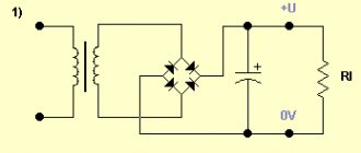
For household appliances that require circuits to be supplied with DC type electricity, it is supplied through power supplies. These are circuits that include a step-down transformer and a rectifying unit. When connecting the power supply to the device, make sure that their voltage and power parameters match. The parameters are indicated on the device body.
Mains power supply 50 Hz
At the moment, both types of electricity get along well in the modern world. Mixed nutrition schemes of consumers only complement each other.
conclusions
Let's try to summarize the information presented. Today it is impossible to imagine the use (both in everyday life and in industry) of any one type of electricity - both direct and alternating current are present almost everywhere. After all, somewhere constant is needed, but its transmission over long distances is impossible, and somewhere variable.
Of course, it has been proven that AC is much safer, but what about devices that help save energy many times over, while they can only work on DC?
It is for these reasons that the currents now “coexist peacefully” in our lives, having ended the “war” that lasted more than 100 years. The only thing that should not be forgotten is that no matter how much safer one is than the other (constant or alternating voltage is not important), it can cause enormous harm to the body, even death.
And that is why when working with voltage it is necessary to carefully observe all safety standards and rules and not forget about care and accuracy. After all, as Nikola Tesla said, electricity should not be feared, it should be respected.
In the modern world, every person has been exposed to electricity since childhood. The first mentions of this natural phenomenon date back to the times of the philosophers Aristotle and Thales, who were intrigued by the amazing and mysterious properties of electric current. But it was only in the 17th century that great scientific minds began a series of discoveries concerning electrical energy that continue to this day.
The discovery of electric current and the creation of the world's first generator by Michael Faraday in 1831 radically changed human life. We are accustomed to the fact that our lives are made easier by devices that operate using electrical energy, but most people still do not understand this important phenomenon. To begin, to understand the basic principles of electricity, you need to learn two basic definitions: electric current and voltage.
Video
Coffee capsule Nescafe Dolce Gusto Cafe O Le Coffee with milk, 3 packs of 16 capsules each
1305 ₽ More details
Coffee capsules Nescafe Dolce Gusto Café Au Lait, 16 pcs.
435 ₽ More details
Apple iPhone XR 128GB
