In the modern world, every person has been exposed to electricity since childhood. The first mentions of this natural phenomenon date back to the times of the philosophers Aristotle and Thales, who were intrigued by the amazing and mysterious properties of electric current. But it was only in the 17th century that great scientific minds began a series of discoveries concerning electrical energy that continue to this day.
The discovery of electric current and the creation of the world's first generator by Michael Faraday in 1831 radically changed human life. We are accustomed to the fact that our lives are made easier by devices that operate using electrical energy, but most people still do not understand this important phenomenon. To begin, to understand the basic principles of electricity, you need to learn two basic definitions: electric current and voltage.
What is electric current and voltage
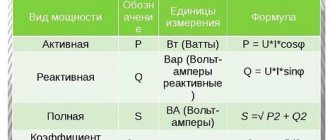
Electric current is the ordered movement of charged particles (electric charge carriers). The carriers of electric current are electrons (in metals and gases), cations and anions (in electrolytes), and holes in electron-hole conductivity. This phenomenon is manifested by the creation of a magnetic field, a change in the chemical composition or heating of the conductors. The main characteristics of the current are:
- The current strength, determined by Ohm's law and measured in Amperes (A), is denoted in formulas by the letter I;
- power, according to the Joule-Lenz law, measured in watts (W), is denoted by the letter P;
- frequency, measured in hertz (Hz).
Electric current, as an energy carrier, is used to obtain mechanical energy using electric motors, to obtain thermal energy in heating devices, electric welding and heaters, to excite electromagnetic waves of various frequencies, to create a magnetic field in electromagnets and to obtain light energy in lighting devices and various types of lamps .
Voltage is the work done by an electric field to move a charge of 1 coulomb (C) from one point on a conductor to another. Based on this definition, it is still difficult to understand what tension is.
In order for charged particles to move from one pole to another, it is necessary to create a potential difference between these poles (this is what is called voltage). The unit of measurement for voltage is the volt (V).
For a final understanding of the definition of electric current and voltage, an interesting analogy can be given: imagine that the electric charge is water, then the pressure of the water in the column is the voltage, and the speed of water flow in the pipe is the strength of the electric current. The higher the voltage, the greater the electric current.
What is alternating current
If you change the polarity of the potentials, the direction of flow of electric current changes. It is this current that is called alternating. The number of changes in direction over a certain period of time is called frequency and is measured, as mentioned above, in hertz (Hz). For example, in a standard electrical network in our country, the frequency is 50 Hz, that is, the direction of current movement changes 50 times per second.
What is direct current
When the ordered movement of charged particles always has only one direction, then such a current is called constant. Direct current occurs in a constant voltage network when the polarity of charges on one side and the other is constant over time. It is very often used in various electronic devices and technology when energy transfer over long distances is not required.
Types used
In most cases, what is called alternating current refers to electricity from the household network. For many people who are far from electrical and electronics, it would be a surprise to learn that AC refers to a much broader concept than electricity from an outlet.
A short list of alternating currents used in power supply networks:
- Single phase. Simple view, variable in direction. Its commercial type has a sinusoidal appearance on the graph and is transmitted over two conductors.
- Three-phase. Electricity for industrial purposes is usually supplied in the form of three separate sine waves with amplitude peaks one-third of a cycle apart. To transmit energy in this way, three (sometimes four) conductors are required.
- Full-wave rectified single-phase. Obtained from an alternating current using a rectifier in such a way that the reverse half of the cycle changes polarity. It can be thought of as a pulsating direct current with no interval between pulses.
- Fully rectified three-phase voltage. Unipolar current with slight ripple. This property distinguishes it favorably from DC.
- Half-wave rectified. It turns out after rectifying the AC in the simplest way by cutting off the part with reverse polarity. The result is a pulsating voltage at intervals with no potential difference across the terminals.
- Pulse voltage. Widely used in modern digital technology and electronics. In many cases, the wave is not a sine wave, but a rectangular one.
Modern devices use a wide variety of current forms, often simultaneously. Even lighting in the 21st century has changed beyond recognition since the days of Edison. A traditional incandescent lamp operated directly from the AC network, and its LED analogue pre-rectifies the sinusoidal voltage, then converting it to the required parameters without the help of additional devices.
However, the war of currents may continue in the very near future. The growing number of DC sources, such as solar panels and wind turbines, has stimulated the development of technologies to transport DC over long distances at losses comparable to AC transmission. Several such operating facilities have already been built in the world and, quite possibly, after some time they will demonstrate in practice their advantages over classical energy systems.
https://youtube.com/watch?v=tl8o5uU5V3c
What is the working principle of alternating current
The English abbreviation AC (Alternating Current) denotes a current that changes its direction and magnitude over time periods. The sinusoid segment “~” is its conventional marking on devices. Applying after this icon and other characteristics is also used.
Below is a figure with the main characteristics of this type of current - nominal frequency and operating voltage.
It should be noted the features of the change in the left graph, made for a single-phase current, in the magnitude and direction of the voltage with the transition to zero over a certain period of time T. For one third of the period, three sinusoids are shifted for a three-phase current on another graph.
O and “b” indicate phases. Any of us has an idea of the presence of 220V in a regular outlet. But for many it will be a discovery that the maximum or otherwise called amplitude value is greater than the acting value by an amount equal to the root of two and is 311 Volts.
Obviously, in the case of direct current, the parameters of direction and voltage remain unchanged, but for alternating current, a transformation of these quantities is observed. In the figure, the opposite direction is the area of the graph below zero.
Let's move on to frequency. This concept means the ratio of periods (full cycles) to a conventional unit of time for a changing current. This indicator is measured in Hertz. The standard European frequency is 50, in the USA the applicable standard is 60G.
This value shows the number of changes in the direction of the current in one second to the opposite and return to the original state.
Alternating current is present when consumer devices are directly connected to electrical panels and sockets. For what reason is there no direct current here? This is done in order to be able to obtain the required voltage in any quantity by using transformers without any significant losses. This technique remains the best way to transmit power on an industrial scale over significant distances with minimal losses.
The rated voltage, which is supplied by powerful generators of power plants, at the output is about 330,000-220,000 Volts. At a substation located in the consumption area, this value is transformed to 10,000V with a transition to a three-phase version of 380 Volts. A separate house is supplied and single-phase voltage reaches your apartment. The voltage between zero and phase will be 220 V, and in the shield between different phases this figure is 380 Volts.
Conversion
For household appliances that require circuits to be supplied with DC type electricity, it is supplied through power supplies. These are circuits that include a step-down transformer and a rectifying unit. When connecting the power supply to the device, make sure that their voltage and power parameters match. The parameters are indicated on the device body.
At the moment, both types of electricity get along well in the modern world. Mixed nutrition schemes of consumers only complement each other.
vote
Article rating
AC voltage
As we know from physics lessons, current is the movement of charged particles that occurs under the influence of an electromagnetic field, potential difference and tension. The main characteristic of any voltage is its dependence on time. Based on this, a distinction is made between constant and variable quantities. The value of a constant practically does not change over time, but the value of a variable changes.
It will be interesting➡ Resistivity for common materials
Ohm's law
In turn, a variable characteristic can be periodic or non-periodic. Periodic is a voltage whose values are repeated at regular intervals. The non-periodic is capable of changing at any period of time.
Scheme for describing the physical meaning
Voltage in an alternating circuit is a parameter that changes its value over time. To simplify explanations, sinusoidal harmonic alternating voltage will be considered in the following.
The minimum time during which a variable repeats is called a period. Absolutely any periodic quantity can be written as a dependence on any function. If time is t, then the dependence will be denoted by F(t). Thus, any period in time has the form: F(t+-T) = F(t), where T is the period.
The physical quantity that is the reciprocal of the period is called frequency. It is equal to 1/T. Its unit of measurement is the hertz, while the unit of measurement of the period is the second.
f = 1/T, 1 Hz = 1/s = s to the minus first power.
Oscillation formulas
Important! The most common functional dependence of a variable network is in the form of a sinusoid. That is why it was taken as the basis for this material.
It is known from mathematics that a sinusoid is the simplest periodic function, and with its help, any other periodic functions can be represented from several sinusoids with multiple frequencies.
Sinusoidal voltage in absolutely any period of time can be described by the instantaneous characteristic: u = U * sin(ωt + φ), where ω = 2πf = 2π/T, where U is the maximum voltage (amplitude), ω is the angular rate of change, φ is the initial phase, which is determined by the displacement of the function relative to the zero coordinate point.
Sine function
Part (ωt + φ) is a phase that characterizes the voltage value in a specific period of time. From this it turns out that amplitude, angular velocity and phase are the main characteristics of variable networks that determine their values in any time interval.
Important! When considering a sine function, the phase is often taken to be zero. In practice, they also often resort to some other parameters, including effective and average voltage, shape factor.
AC voltage regulator
Direction of movement
The current is directed in the direction in which the positively charged particles are moving. And they move from the positive pole of the source to the negative. This rule is unshakable even for those cases where free charged particles carry only a negative charge (for example, electrons in metal conductors).
The current is still considered to be directed from “plus” to “minus”, although in fact the charge carriers are moving in the opposite direction.
Difference between AC and DC voltage
The difference between these two quantities is not only in the name. It all depends on the type of current. In a regular outlet at home, the current is alternating. This means that the direction of movement of charged particles in it is constantly changing. Moreover, alternating current forces have different frequencies and voltages. For example, in a 220-volt outlet, the normal frequency is 50 Hz, which means the electrons and their charges change direction 50 times per second. Voltage in this regard refers to the maximum speed at which electrons move through a circuit.
Constant and variable characteristics
Another difference between the variable direction of movement of particles and, as a consequence, voltage from a constant one is that the charge in it is constantly changing. The value of U in such a network is either 100% or 0%. If it was always full, a very large diameter wire would be required.
A constant direction is a current that does not change the coordinates of its movement. It can be observed in batteries and batteries. It gets there through a charger, which converts any flow from the outlet into a constant one.
Antiphase
Principle of operation
Mechanical energy is converted by the generator shown in the figure into electrical energy as follows:
Due to such a phenomenon as electromagnetic induction, when the frame “4” rotates, placed in the magnetic field “3” (arising between the different poles of the magnet “2”), an emf “5” is formed in it. Voltage is supplied to the network through current collectors “7” from ring contacts “6”, to which frame “4” is connected.
Video: direct and alternating current - differences
As for the magnitude of the EMF, it depends on the speed of intersection of the power lines “3” by the frame “4”. Due to the characteristics of the electromagnetic field, the minimum crossing speed, and therefore the lowest value of the electromotive force, will be at the moment when the frame is in a vertical position, respectively, the maximum - in a horizontal position.
Taking into account the above, in the process of uniform rotation an emf is induced, the characteristics of the magnitude and direction of which change with a certain period.
What is the current in the outlet - direct or alternating?
People who are more or less familiar with electrical engineering can easily answer the question of what current is in the outlet. Of course it's variable. This type of electricity is much easier to produce and transmit over long distances, and therefore the choice in favor of alternating current is obvious.
There are two types of current - direct and alternating. To understand the difference and determine whether the outlet has direct or alternating current, you should delve into some technical features. Alternating current has the property of changing in direction and magnitude. Direct current has stable qualities and direction of movement of charged particles.
Alternating current comes out of the power plant generators with a voltage of 220-440 thousand volts. When approaching an apartment building, the current is reduced to 12 thousand volts, and at the transformer station it is converted to 380 volts.
Advice
The voltage between phases is called linear. The low-voltage section of the step-down substation produces three phases and a zero (neutral) wire. Energy consumers are connected from one of the phases and the neutral wire.
Thus, single-phase alternating current with a voltage of 220 volts enters the building.
The distribution diagram of electricity between houses is presented below:
In the home, electricity is supplied to the meter, and then through automatic machines to the boxes of each room. The boxes contain wiring throughout the room for a couple of circuits - electrical outlets and lighting equipment.
The machines can be provided one for each room or one for each circuit.
Taking into account how many amperes the outlet is designed for, it can be included in a group or connected to a dedicated circuit breaker.
Alternating current accounts for approximately 90% of all electricity consumed. Such a high specific gravity is due to the peculiarities of this type of current - it can be transported over considerable distances by changing the voltage at substations to the required parameters.
Sources of direct current are most often batteries, galvanic cells, solar panels, thermocouples.
Direct current is widely used in local networks of automobile and air transport, in computer electrical circuits, automatic systems, radio and television equipment.
Direct current is used in contact networks of railway transport, as well as on ship installations.
The diagram below shows the fundamental differences between direct and alternating currents.
Home electrical network parameters
The main parameters of electricity are its voltage and frequency. The standard voltage for home electrical networks is 220 volts. The generally accepted frequency is 50 hertz. However, in the USA a different frequency value is used - 60 hertz. The frequency parameter is set by the generating equipment and is unchanged.
It will be interesting➡ What is the difference between an RCD and a difavtomat
The voltage in the network of a particular house or apartment may be different from the nominal value (220 volts). This indicator is influenced by the technical condition of the equipment, network loads, and substation load. As a result, the voltage may deviate from the specified parameter in one direction or another by 20–25 volts.
Current load
All sockets have a certain marking, by which you can judge the permissible current load. For example, the designation "5A" indicates a maximum current of 5 amperes. Acceptable indicators must be observed, since otherwise the equipment may fail, including fire.
The markings on the sockets are shown in the figure below:
All legally sold electrical appliances are accompanied by a passport indicating the power consumption or current load rating.
The largest consumers of electricity are household appliances such as air conditioners, microwave ovens, washing machines, electric stoves and ovens.
For normal operation, such devices will need an outlet with a load of at least 16 amperes.
note
If the documentation for electrical household appliances does not contain information about the consumed amperes (current strength in the outlet), the required values are determined using the electric power formula:
The power indicator is in the passport, the network voltage is known. To determine electricity consumption, you need to divide the power indicator (indicated only in watts) by the voltage value.
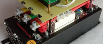
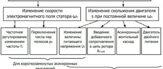
Efficiency of Electronic Commutated Motors
EC motors are brushless DC motors controlled by external electronics - either an electronic board or a frequency converter.
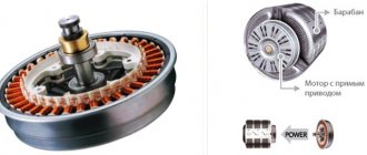
The rotor contains permanent magnets, and the stator has a set of stationary windings. Switching is performed using electronic circuits. The “board” switches phases in the stationary windings to keep the motor turning. This allows the armature current to be maintained. When the voltage of the correct polarity is connected at the right time, the accuracy of the electrical machine increases. Because the motor speed is controlled by external electronics, EC motors do not have a limited synchronous speed. EC motors have several advantages. Since they do not have brushes, they do not spark and their service life is longer due to the absence of brushes, they have less losses due to the “smart control” of the stator. They provide better performance and controllability than induction motors. In terms of size, small electric motors can reach the same dimensions as traditional AC or DC electric machines.
Power distribution is much better with electronically controlled cars. Brushless direct current (BLDC) motors rely on a constant voltage power supply. When using AC machines, there are additional costs and system complexity if regulation is required. EC motors can be directly connected to AC sources thanks to the presence of an electronic control system. Moreover, they are slightly susceptible to changes in the frequency and voltage of the network, from which we can conclude that small dips in the network voltage will not have a significant effect on the power of the machine, unlike asynchronous electric motors.
If you compare the efficiency of an EC machine with an alternating current machine with a shaded pole or with a capacitor electric motor, you can see that a shaded pole machine has an efficiency of about 15% - 25%, capacitor electric motors 30% - 50%, and EC machines have an efficiency within the range 60% - 75% and are the most efficient and energy saving.
The range of changes in efficiency for capacitor asynchronous machines is quite large and lies in the range of 30% - 50%, which is especially noticeable when they are not fully loaded, for example, when working in ventilation and air conditioning systems. EC motors have a smaller range of efficiency changes when operating at different speeds and with different loads. As a rule, such machines have an efficiency of at least 70%, and in machines operating with nominal parameters it can exceed 80%.
Electronically controlled machines have a speed controller as a built-in option. AC motors can only have this option with an external controller (frequency converter). Frequency converters change the amplitude and frequency of the voltage supplied to the electric motor, thereby generating higher harmonics, which negatively affect the electric machine, contributing to its overheating, and, as a result, reducing its service life.
The switching circuits accept pulse width modulated inputs from 4 to 20 mA and 0 to 10 V. This allows speed control from 10% to 100%. Monitoring EC motors using an integrated circuit is simple and can be easily accessed by the designer to provide feedback. Finally, EC motors provide smooth starting, reduced noise and lower motor temperatures.
Electronically controlled electrical machines are typically used for low power applications such as small fans, servo motors, and motion control systems. However, thanks to recent advances in electronics and chemistry, EC motors are finding their way into larger manufacturing applications, up to 12 kW and above.
Where does the voltage come from?
To supply electricity to an outlet, it must be generated somehow. To generate electricity, technologies from the late 19th century are still mostly used - electromagnetic induction, which converts mechanical energy into electrical energy. In other words, generators. The difference between generators is only in how mechanical energy is supplied. Previously, these were bulky steam engines. Over time, hydraulic turbines for running water (hydroelectric power stations), internal combustion engines, and nuclear reactors were added.
The operating principle of the generator is based on magnetic induction. The rotational movement of the generator is converted into electric current. That is, we can say that a generator is the same electric motor, but of reverse action. If voltage is applied to the electric motor, it will begin to rotate. The generator works in reverse. The rotational movement of the generator shaft is converted into electric current. Therefore, in order to rotate the generator shaft, we will need some kind of external energy. It could be steam that spins the turbine, which in turn spins the generator shaft
Operating principle of thermal power plants
or it can be the force of the water flow, which, with the help of a hydraulic turbine, spins the generator shaft, and it, in turn, also generates electric current
Operating principle of hydroelectric power station
Well, or it could even be a windmill
Wind power plant
In short, the principle is the same everywhere.
By the way, a nuclear reactor is not capable of generating energy on its own. In fact, a nuclear power plant is the same primitive steam boiler, where the working fluid is ordinary steam. Yes, today there are other ways to generate electricity, such as the same solar cells, beta-galvanic and isotope nuclear batteries, “mythical” tokomaks. However, the above-mentioned “high-tech” has significant limitations - the prohibitive cost of materials, installation and setup, dimensions and low efficiency. Therefore, it is not worth seriously considering all this as a full-fledged high-power power plant (at least in the next couple of decades).
EMF sources
Sources of electric current of any kind are of two types:
- primary, with their help, electricity is generated by converting mechanical, solar, thermal, chemical or other energy into electrical energy;
- secondary, they do not generate electricity, but convert it, for example, from variable to constant or vice versa.
The only primary source of alternating electric current is a generator; a simplified diagram of such a device is shown in the figure.
Simplified illustration of generator design
Designations:
- 1 – direction of rotation;
- 2 – magnet with poles S and N;
- 3 – magnetic field;
- 4 – wire frame;
- 5 – EMF;
- 6 – ring contacts;
- 7 – current collectors.
Excursion into history
So, the generator at our power plant converts mechanical energy into electrical energy. What's next? In what form and how exactly to transfer energy to the consumer? How to avoid colossal transmission losses?
Amazingly, such a situation actually existed! In the Russian Empire, until the beginning of the 20th century, there was complete confusion. A separate power plant was built next to each “large” consumer of electricity (a factory, the farmstead of a successful merchant, or a hotel for people of noble blood). There were many competing companies providing electrification services and, subsequently, their own electrical equipment tailored only for their network. Each electricity supplier set its own power grid parameters - voltage, frequency. There were even DC power grids! A person who bought, for example, light bulbs from the Lodygin and Co. Electric Lighting Partnership could only use them in the electrical network of the same company. If connected to the General Electric network, this light bulb would immediately fail - the network voltage of this company was significantly higher than necessary, not to mention other parameters.
Only in 1913 did imperial engineers decide to transmit electricity over long distances via overhead wire lines, eliminating the need to build power plants “at every outlet.” On the eve of the coming great war and the surge of patriotism, the authorities began to think about import substitution. Well, just like in our time, after the 2014 crisis). Many small Western firms (except German and French) were financially and legally suppressed; preferences and benefits were given only to domestic partnerships and enterprises. As a result, this led to monopoly in the electricity supplier market and, unwittingly, standardization of electrical network parameters.
Since Berlin and Paris were already electrified by a single power grid with 220 volt alternating voltage, domestic companies also adopted this standard. It was more convenient for people to use electrical appliances of a single type, without worrying that their newfangled electric vacuum cleaner would burn out at a new place of residence due to other parameters of the power grid. There was a complete displacement of many small firms - no one wanted to use their services and their devices, although they were forced to adapt to a single standard of the electrical network. Those same 220 volts AC.
A Brief History of Electricity
Who invented electricity? And no one! People gradually understood what it was and how to use it.
It all started in the 7th century BC, on one sunny (or maybe rainy, who knows) day. Then the Greek philosopher Thales noticed that if you rub amber on wool, it will attract light objects.
Then there were Alexander the Great, wars, Christianity, the fall of the Roman Empire, wars, the fall of Byzantium, wars, the Middle Ages, the Crusades, epidemics, the Inquisition and more wars. As you understand, people had no time for any electricity or ebonite sticks rubbed with wool.
In what year was the word “electricity” invented? In 1600, the English naturalist William Gilbert decided to write the work “On the Magnet, Magnetic Bodies and the Great Magnet - the Earth.” “electricity” appeared .
One hundred and fifty years later, in 1747, Benjamin Franklin, whom we all love very much, created the first theory of electricity. He viewed this phenomenon as a fluid or immaterial liquid.
It was Franklin who introduced the concept of positive and negative charges (before that, glass and resin electricity were separated), invented the lightning rod and proved that lightning is electrical in nature.
Everyone loves Benjamin, because his portrait is on every hundred dollar bill. In addition to his work in the exact sciences, he was a prominent political figure. But contrary to popular belief, Franklin was not the President of the United States.
Voltage formula
There is a formula in physics, although it has no practical application. The official formula is written like this.
voltage formula
Where
A is the work done by the electric field to move a charge along a section of the circuit, Joules
q - charge, Coulomb
U—voltage on a section of the electrical circuit, Volts
In practice, the voltage across a section of a circuit is derived through Ohm's law.
It will be interesting➡ How to properly connect an RCD
voltage from Ohm's law
Where
I - current, Amperes
R - resistance, Ohms
Three-phase generators
Note that the most cost-effective way to obtain alternating electric current is to use a three-phase generator. A simplified diagram of its design is shown in the figure.
Three-phase generator device
As you can see, the generator uses three coils, placed with an offset of 120°, connected to each other by a triangle (in practice, such a connection of the generator windings is not used due to low efficiency). When one of the poles of the magnet passes by the coil, an emf is induced in it.
Graphical representation of the generated three-phase electric current
Current voltage - what does it mean?
This term can be heard very often in colloquial speech. Current, in this case, is electric current. It turns out that current voltage is the voltage of electric current. It's just how we shorten it. As I said above, current can be alternating or constant. Direct current and constant voltage are synonymous, as are alternating current and alternating voltage. It turns out that the phrase “current voltage” tells us what the voltage is between two points or wires in an electrical circuit.
For example, to the question “what is the current voltage in the socket” you can safely answer: alternating current 220 Volts,” and to the question “what is the current voltage of a car battery,” you can answer “12 Volts DC.” So don't be scared).
Symbols on electrical devices and diagrams
Often there is a need to determine at what current a device operates. After all, connecting a device operating on direct current to an alternating current electrical network will inevitably lead to unpleasant consequences: damage to the device, fire, electric shock. For this purpose, there are generally accepted symbols in the world for such systems and even color marking of wires.
Conventionally, on electrical appliances operating on direct current, one line, two solid lines, or a solid line together with a dotted line, located one below the other, are indicated. Also, such a current is marked with the Latin letters DC . The electrical insulation of wires in DC systems is colored red for the positive wire and blue or black for the negative wire.
What is the difference between AC and DC current
The general concept of electric current can be expressed as the movement of various charged particles (electrons, ions) in a certain direction. And its value can be characterized by the number of charged particles that passed through the conductor in a certain period of time.
If the value of charged particles of 1 coulomb passes through a certain cross-section of a conductor in a time of 1 second, then we can talk about a current strength of 1 ampere flowing through the conductor. This determines the number of amperes or current. This is the general concept of current. Now let's look at the concept of alternating and direct current and their differences.
A direct electric current, by definition, is a current that flows in only one direction and does not change over time. Alternating current is characterized by the fact that it changes its direction and magnitude over time. If direct current is graphically displayed as a straight line, then alternating current flows through the conductor according to the sine law and is graphically displayed as a sine wave.
Graphical representation of DC current
Since alternating current varies according to the law of a sinusoid, it has such parameters as the period of a complete cycle, the time of which is denoted by the letter T. The frequency of alternating current is the inverse of the period of a complete cycle. The frequency of alternating current is expressed by the number of complete periods in a certain period of time (1 sec).
Graphical representation of alternating current
There are 50 such periods in our AC power network, which corresponds to a frequency of 50 Hz. F = 1/T, where the period for 50 Hz is 0.02 sec. F =1/0.02 = 50 Hz. Alternating current is denoted by the English letters AC and the sign “~”. Direct current is designated DC and has a “-” symbol. In addition, alternating current can be single-phase or multiphase. A three-phase network is mainly used.
General definitions
The physical process in which charged particles move in an orderly (directional) manner is called electric current. It is usually divided into variable and constant. For the first, the direction and magnitude remain unchanged, but for the second, these characteristics change according to a certain pattern.
The above definitions are greatly simplified, although they explain the difference between direct and alternating current. To better understand what this difference is, it is necessary to provide a graphical representation of each of them, as well as explain how the alternating electromotive force is generated in the source. To do this, let us turn to electrical engineering, or rather its theoretical foundations.
Graphic images
Thanks to the use of the graphical method, it is possible to obtain a visual representation of dynamic changes in various quantities. Below is a graph of voltage changes over time for a 3336L (4.5 V) galvanic cell.
The horizontal axis displays time, the vertical axis shows voltage
As you can see, the graph is a straight line, that is, the source voltage remains unchanged.
Now we present a graph of the dynamics of voltage changes during one cycle (full revolution of the frame) of the generator.
The horizontal axis displays the angle of rotation in degrees, the vertical axis displays the magnitude of the emf (voltage)
For clarity, we will show the initial position of the frame in the generator, corresponding to the starting point of the report on the graph (0°)
Frame initial position
Designations:
- 1 – magnet poles S and N;
- 2 – frame;
- 3 – direction of rotation of the frame;
- 4 – magnetic field.
Now let's see how the EMF will change during one cycle of rotation of the frame. At the initial position, the EMF will be zero. During the rotation process, this value will begin to increase smoothly, reaching a maximum at the moment when the frame is at an angle of 90°. Further rotation of the frame will lead to a decrease in the EMF, reaching a minimum at the moment of rotation by 180°.
Continuing the process, you can see how the electromotive force changes direction. The nature of the changes in the EMF that has changed direction will be the same. That is, it will begin to increase smoothly, reaching a peak at the point corresponding to a 270° rotation, after which it will decrease until the frame completes a full rotation cycle (360°).
If the graph is continued for several rotation cycles, we will see a sinusoid characteristic of alternating electric current. Its period will correspond to one revolution of the frame, and its amplitude will correspond to the maximum value of the EMF (forward and reverse).
Now let's move on to another important characteristic of alternating electric current - frequency. The Latin letter “f” is used to denote it, and its unit of measurement is hertz (Hz). This parameter displays the number of complete cycles (periods) of EMF change within one second.
The frequency is determined by the formula: . The “T” parameter displays the time of one complete cycle (period), measured in seconds. Accordingly, knowing the frequency, it is easy to determine the time of the period. For example, in everyday life an electric current with a frequency of 50 Hz is used, therefore, its period time will be two hundredths of a second (1/50 = 0.02).
Advantages of AC
The issue of increasing and decreasing alternating voltage at the current level of technical development is much easier to solve than direct electric current.
Such transformations are quite easily carried out using a relatively simple device - a transformer. The transformer has a high efficiency, which reaches 99%. This means that no more than one percent of the power is lost when the voltage increases or decreases. In addition, the transformer allows you to decouple high voltage from lower voltage, which is a very powerful argument for most electrical installations.
The use of a three-phase AC system can further improve the efficiency of the power supply system. To transmit electricity of the same power, fewer wires will be required than with single-phase alternating current. In addition, a three-phase transformer is smaller in size than a single-phase transformer of equal power.
AC electric machines, in particular squirrel-cage asynchronous motors, have a much simpler design than DC motors. The main advantage of three-phase asynchronous motors is the absence of a commutator-brush assembly. This reduces the cost of manufacturing and operating such electrical machines. In addition, due to the absence of a commutator-brush assembly, asynchronous motors have many times more power compared to DC motors.
What is the reason for the variety of electric currents?
Many may have a well-founded question - why use such a variety of electric currents if you can choose one and make it standard? The thing is that not every type of electric current is suitable for solving a particular problem.
As an example, we give conditions under which using constant voltage will not only be unprofitable, but sometimes impossible:
- the task of transmitting voltage over distances is easier to implement for alternating voltage;
- it is almost impossible to convert direct electric current for heterogeneous electrical circuits that have an uncertain level of consumption;
- maintaining the required voltage level in direct current circuits is much more difficult and expensive than alternating current;
- motors for alternating voltage are structurally simpler and cheaper than for direct voltage. At this point, it should be noted that such motors (asynchronous) have a high level of starting current, which does not allow them to be used for solving certain problems.
Now we give examples of problems where it is more appropriate to use constant voltage:
- To change the rotation speed of asynchronous motors, you need to change the frequency of the power supply network, which requires complex equipment. For motors running on direct current, it is enough to change the supply voltage. That is why they are installed in electric vehicles;
- power supply of electronic circuits, galvanic equipment and many other devices is also carried out by direct electric current;
- DC voltage is much safer for humans than alternating voltage.
Based on the examples listed above, there is a need to use different types of voltage.