Rectifiers. How and why.
So, my dears, we have assembled our circuit and it’s time to check it, test it and enjoy this happiness. Next up is connecting the circuit to the power source. Let's get started. We won’t dwell on batteries, accumulators and other power supplies; we’ll move straight to mains power supplies. Here we will look at existing rectification schemes, how they work and what they can do. For experiments we will need single-phase (at home from an outlet) voltage and the corresponding parts. Three-phase rectifiers are used in industry, we will not consider them either. If you grow up to be an electrician, then please.
The power supply consists of several most important parts: Mains transformer - indicated in the diagram as similar to the one in the figure,
Rectifier - its designation may vary. The rectifier consists of one, two or four diodes, depending on which rectifier. Now we'll figure it out.
a) – a simple diode. b) – diode bridge. Consists of four diodes connected as in the figure. c) – the same diode bridge, only drawn simpler for brevity. The contact assignments are the same as for the bridge under letter b).
Filter capacitor. This thing is unchanged in both time and space, and is designated as follows:
There are many designations for a capacitor, as many as there are designation systems in the world. But in general they are all similar. Let's not get confused. And for clarity, let’s draw a load, denote it as Rl - load resistance. This is our scheme. We will also outline the contacts of the power source to which we will connect this load.
Next are a couple of postulates. – The output voltage is defined as Uconst = U*1.41. That is, if we have 10 volts of alternating voltage on the winding, then on the capacitor and on the load we will get 14.1 V. Like that. – Under load, the voltage sags a little, and how much depends on the design of the transformer, its power and the capacitance of the capacitor. – Rectifier diodes should be 1.5-2 times more current than required. For stock. If the diode is intended for installation on a radiator (with a nut or bolt hole), then at a current of more than 2-3A it must be installed on the radiator.
Let me also remind you what bipolar voltage is. If someone has forgotten. We take two batteries and connect them in series. The middle point, that is, the point where the batteries are connected, will be called the common point. It is popularly known as ground, ground, body, common wire. The bourgeoisie call it GND (ground), often referred to as 0V (zero volts). Voltmeters and oscilloscopes are connected to this wire; relative to it, input signals are supplied to the circuits and output signals are taken. That’s why its name is common wire. So, if we connect the tester with the black wire to this point and measure the voltage on the batteries, then the tester will show plus 1.5 volts on one battery, and minus 1.5 volts on the other. This voltage +/-1.5V is called bipolar. Both polarities, that is, plus and minus, must be equal. That is, +/-12, +/-36V, +/-50, etc. A sign of bipolar voltage is if three wires go from the circuit to the power supply (plus, common, minus). But this is not always the case - if we see that the circuit is powered by a voltage of +12 and -5, then such power is called two-level, but there will still be three wires to the power supply. Well, if as many as four voltages are supplied to the circuit, for example +/-15 and +/-36, then we will simply call this power supply - bipolar two-level.
Well, now to the point.
1. Bridge rectification circuit.
The most common scheme. Allows you to obtain unipolar voltage from one winding of the transformer. The circuit has minimal voltage ripple and is simple in design.
2. Half-wave circuit.
Just like the pavement, it prepares us a unipolar voltage from one winding of the transformer. The only difference is that this circuit has double the ripple compared to a bridge circuit, but one diode instead of four greatly simplifies the circuit. It is used for small load currents, and only with a transformer much larger than the load power, because such a rectifier causes one-sided magnetization reversal of the transformer.
3. Full-wave with midpoint.
Two diodes and two windings (or one winding with a midpoint) will supply us with a low-ripple voltage, plus we will get lower losses compared to a bridge circuit, because we have 2 diodes instead of four.
4. Bridge circuit of a bipolar rectifier.
For many, this is a sore subject. We have two windings (or one with a midpoint), we remove two identical voltages from them. They will be equal, the ripples will be small, since the circuit is a bridge circuit, the voltage on each capacitor is calculated as the voltage on each winding multiplied by the root of two - everything is as usual. A wire from the midpoint of the windings equalizes the voltage on the capacitors if the positive and negative loads are different.
5. Voltage doubling circuit.
These are two half-wave circuits, but with diodes connected in different ways.
It is used if we need to get double the voltage. The voltage on each capacitor will be determined by our formula, and the total voltage on them will be doubled. Like the half-wave circuit, this one also has large ripples. You can see a bipolar output in it - if the middle point of the capacitors is called ground, then it turns out like in the case of batteries, take a closer look. But you can’t get a lot of power out of such a circuit. Read also: KME 1810 connection diagram
6. Obtaining different polarity voltage from two rectifiers.
It is not at all necessary that these are the same power supplies - they can be either different in voltage or different in power. For example, if our circuit consumes 1A at +12 volts, and 0.5A at -5 volts, then we need two power supplies - +12V 1A and -5V 0.5A. You can also connect two identical rectifiers to obtain a bipolar voltage, for example, to power an amplifier.
7. Parallel connection of identical rectifiers.
It gives us the same voltage, only with double the current. If we connect two rectifiers, then we will have a double increase in current, three - triple, etc.
Well, if everything is clear to you, my dears, then I’ll probably give you some homework. The formula for calculating the filter capacitance for a full-wave rectifier is:
For a half-wave rectifier, the formula is slightly different:
The two in the denominator is the number of rectification “cycles”. For a three-phase rectifier, the denominator will be three.
In all formulas, the variables are named as follows: Cf – capacitance of the filter capacitor, µF Po – output power, W U – output rectified voltage, V f – frequency of alternating voltage, Hz dU – ripple range, V
For reference - permissible ripple: Microphone amplifiers - 0.001. 0.01% Digital technology – ripple 0.1. 1% Power amplifiers - ripple of a loaded power supply 1. 10% depending on the quality of the amplifier.
These two formulas are valid for voltage rectifiers with a frequency of up to 30 kHz. At higher frequencies, electrolytic capacitors lose their efficiency, and the rectifier is designed a little differently. But that is another topic.
One of the most common current converters are rectifiers of alternating current into pulsating (constant in the direction of movement of the carriers, but variable in instantaneous magnitude) current. They have a very wide application. Conventionally, they can be divided into low-power rectifiers (up to several hundred watts and high-power rectifiers (kilowatts and more)).
Operating principle of the rectifier
The block diagram of the rectifier is shown below:
Its main part is the rectifying device B, formed from diodes combined in a special way. This is where the conversion of alternating current into pulsating direct current occurs. Alternating voltage is supplied to the rectifying device through the transformer Tr. In some cases, there may not be a transformer (if the voltage of the power network corresponds to that required for the operation of the rectifier). The transformer (if there is one) in most cases also has features in the connection of its windings. The pulsating current, as a rule, is not constant in value at every instant of time, and when it is necessary to have a smoother value than that obtained after the rectifying device, filters F are used. If necessary, the rectifier is supplemented with a voltage or current stabilizer St, which maintains them at a constant level if the power network parameters change for various reasons. The block diagram is completed by load H, which significantly affects the operation of the entire device and is therefore considered an integral part of the entire converter.
The rectifier itself is that part of it that is circled in the figure above with a dotted line and consists of a transformer and a rectifier device.
This subsection discusses low-power rectifiers, which are necessary to provide constant voltage to all kinds of devices in the areas of control, regulation, current amplifiers, low-power generators, and so on. As a rule, they are powered by single-phase alternating voltage 220 or 380 V with a frequency of 50 Hz.
What types of rectifiers are there?
The construction of devices that rectify alternating current is based on the function of the final unit. If it is only necessary to equalize vibrations, assembly on printed circuit boards is carried out using uncontrolled semiconductor elements - diodes. This is how the simplest leveling elements are built.
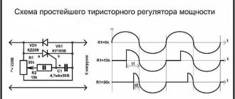
If it is necessary to change the level of power that is transmitted to the receiving equipment, the device is assembled using controlled valves (thyristors). These rectifiers are required to operate some electrically powered motors. By adjusting the supplied voltage, the rotation speed of the rotor changes.
N-phase rectifiers
Such devices have more than 3 phases for current rectification. Other design features vary. A multiphase rectifier can consist of either a full bridge or a quarter and half bridge. Based on the number of inputs and parallelization, they are divided into separate ones, united by stars or rings. In addition, there are sequential types.
Which capacitor to place after the diode bridge - Diode bridge, how to choose the correct capacitor value? — Habr Q&A — ESR Energy
Classification, properties, diagrams, online calculator. Calculation of the capacity of the smoothing capacitor.
Expert opinion
It-Technology, Electrical power and electronics specialist
Ask questions to the “Specialist for modernization of energy generation systems”
Diode Connection Diagram. Modern devices of this type are relatively inexpensive, compact, easy to connect and do not require maintenance during operation. Ask, I'm in touch!
Zero rectification circuit
It is advisable to consider the operating principle of the simplest single-phase current rectifier using the so-called zero circuit. Although it is now relatively rare (as discussed below), knowledge of the physical processes that occur in this circuit is very important for understanding further material.
The zero circuit looks like this:
Transformer Tr has two windings on the secondary side, connected in series in such a way that, relative to the midpoint a, the voltages at the free ends of windings b and c are equal in magnitude, but opposite in phase. The rectifier device is formed by two diodes D1 and D2, which are connected together at their cathodes, while each anode is connected to a corresponding winding. The load Zn is connected between the cathodes of the diodes and the point of the transformer.
Let's look at how pulsating voltage occurs across a load. First, we will consider the load to be purely active resistance, Zн=Rн. When the voltage in the windings changes according to a sinusoidal law, then during that half-cycle when a positive potential is applied to the anode of the diode, direct current will flow. Since the voltage across the diode is a fraction of a volt, we will neglect it. Then the entire positive half-wave of alternating voltage will be applied simply to the load Rн. When the voltage is applied negative to the anode, there will be no current (we will also neglect the small reverse current of the diode). Thus, only a positive half-wave of alternating voltage will reach the load during half the period. The second half of the period will be free of current.
The secondary windings are connected in antiphase, the load is common to both windings, thus, while current flows in one of them (for example, in the upper one), the other will be free from it and vice versa.
Read also: Tool alloy steels marking
Therefore, in the load, each half-cycle will be filled with a half-wave of alternating voltage:
And the rectified voltage Ud will have the form of identical half-waves, which are repeated with a period half as long as the period of the alternating voltage in the power supply network (2π radians). For generalization, which will be convenient, we will further assume that the period of change of the rectified voltage is less than 2π by m times and equals 2π/m (in our case m-2). If the load is an active resistance Rн, then the current in it id will follow the voltage curve.
The considered circuit will have the disadvantage that in the secondary windings, compared to the primary, there are significant current ripples, because these windings operate in turn. Since they are wound on one core, the magnetic flux in the latter will be variable, therefore in the primary winding the current will be variable, having both positive and negative half-waves. As you know from the electrical engineering course, the effective and average values of current or voltage are the same only for direct current. The greater the pulsation, the greater the effective value will be relative to the average. Therefore, the power on both sides of the transformer will not be the same. However, there is only one transformer, and the volume of iron for its core should be selected based on a single power value.
Therefore, we conditionally introduced the concept of typical power of a transformer, which is equal to the average of the powers of both sides:
Diode bridge operation
The operating principle of the diode bridge is as follows. Its input, indicated by an alternating symbol, is supplied with alternating current with changing polarity. The frequency of changes, as a rule, coincides with the frequency in the electrical network. At the output, where the positive and negative terminals are located, a current of exclusively one polarity is obtained.
In urban conditions, the voltage in the network, as a rule, remains constant, but protecting the apartment from voltage surges becomes important. Here it’s time to remember the wonders of electronics, since “iron-wire” electrical engineering does not know effective, simple and cheap ways to smooth them out.
Ask around at electrical and radio stores for a surge protector; they are also called “protective barriers”. You can see what this looks like in the illustration. Modern devices of this type are relatively inexpensive, compact, easy to connect and do not require maintenance during operation.
What kind of lighting do you prefer?
Built-in Chandelier
But don’t think about the autotransformer at the dacha - the protective barrier only eliminates voltage surges; It cannot keep the voltage in the socket all the time at a stably low voltage. Supercapacitors are used as energy storage devices in such devices, and although they are “super”, they are still not electric generators.
To obtain a constant voltage from an alternating voltage means to rectify it.
To rectify, you need to make sure that the current can only flow in one direction.
An element that allows current to flow in only one direction is called a diode.
In the diagrams the diode is designated as follows
If you use one diode for rectification, the voltage across the load will turn out to be pulsating.
However, this voltage can already be used to power some low-power DC devices. There is a constant component to this pulsating voltage.
If the alternating voltage is, for example, 10 Volts, then the direct component of the rectified voltage will be 4.5 Volts.
Not enough, for some cases it’s normal, but in our case it’s not enough.
Expert opinion
It-Technology, Electrical power and electronics specialist
Ask questions to the “Specialist for modernization of energy generation systems”
Simple calculation of a rectifier with a network transformer Based on this circuit, it is possible to construct 12 and 24 pulse rectification circuits that use serial and parallel connection of circuits with different combinations of star or delta connections of the secondary windings of the transformer. Ask, I'm in touch!
Bridge rectifier or Graetz circuit
This drawback can be corrected by using a rectifying device in the form of a so-called bridge (Graetz circuit):
In this case, the first half-cycles will work, for example, diodes D2 and D4, and the second half-cycles - D1 and D3. At the load each time there will be a full half-wave of the secondary voltage:
The bridge circuit also has a less complex, lighter and cheaper transformer. As we will see later, it has several other advantages.
It is interesting that this circuit appeared historically earlier than the zero circuit, but was not widespread because, firstly, it had four diodes instead of two. However, the main thing was not their number, but the fact that during operation, every half cycle, the current passes through two series-connected diodes, onto which double voltage drops. At that time, there were no semiconductor diodes yet, and vacuum or mercury diodes had a significant voltage drop when direct current passed, which significantly reduced the efficiency. It turned out that a more complex neutral circuit transformer, but with one diode in the current rectification circle, is more economically profitable than a bridge circuit with double the number of diodes and double the energy consumption for them. And only the advent of relatively cheap semiconductor diodes with a very small forward voltage drop made it possible to turn to bridge circuits, which have now practically replaced the zero circuit (in this, if desired, one can see a manifestation of one of the dialectical laws - development in a spiral).
Basic relations for a rectifier
Let us derive some important formulas that describe the processes that exist in this scheme. We will assume that the given values are the average voltage across the load Ud and the average current in it Id.
Average rectified voltage
Let's remember this expression for later. In our case m=2 and . Since Ud is considered given, then
Amplitude value of secondary voltage
From the previous expression we have:
Transformer ratio
This coefficient determines the ratio of the supply network to the voltage on the secondary side winding:
Effective value of the secondary winding current
The current of the secondary winding at the same time is the current in the load. Since the load is purely active and the current in it follows the shape of a pulsating voltage, then between its average value and its effective value there is the same relationship as for voltages, that is
Effective value of the primary winding current
The current in the primary winding repeats, taking into account n, the current of the secondary winding:
Transformer power
The powers of the primary and secondary sides of the transformer in this circuit are the same, therefore:
Rectified voltage ripple
The pulsating voltage consists of an average value Ud and an infinite number of harmonic components, the amplitudes of which can be determined using Fourier formulas. If the origin of coordinates is chosen as in the figure, then only cosine harmonics will be present in the harmonic composition (since the curve is symmetrical relative to the coordinate axis). The amplitude of the kth harmonic is determined by the formula:
Where: l – half-cycle π/m;
The first harmonic U(1)m will have the largest amplitude, so we determine only it, assuming that k=1:
Replacing we get:
The ratio of the first harmonic to the average value is called the ripple factor:
Let's remember this formula for the future, but now note that in our case, for m – 2, q – 2/3. These are large ripples - the amplitude of the first harmonic is 67% of the average value of the rectified voltage.
Average diode current
As we have already seen, the diodes work in turn - each of them conducts on average half of the total current that is in the load. Therefore, each of the diodes must be designed for current Iв = Id/2
Highest reverse voltage across diode
While diode B1 is conducting, it can be considered closed, and then the voltage of the secondary winding will be applied to diode B2 in the opposite direction. Therefore, each of the diodes must be designed for its amplitude value:
The full-wave rectifier is more common than the half-wave rectifier, this is due to the numerous advantages of such a circuit. To explain exactly what the advantage is, we should turn to the theoretical foundations of electrical engineering.
First of all, let's look at the difference between a full-wave rectifier and a half-wave rectifier; to do this, you need to understand the operating principle of each of them. Examples of circuits with oscillograms will give a clear idea of the advantages and disadvantages of these devices.
Educational program KO. Lecture No. 1 Electric current rectification circuits.
Electric current rectification circuits. Electric current rectifier
– an electronic circuit designed to convert alternating electric current into direct (unipolar) electric current. In semiconductor equipment, rectifiers are made using semiconductor diodes. In older and high-voltage equipment, rectifiers are made using electric vacuum devices - kenotrons. Previously, selenium rectifiers were widely used.
First, let's remember what alternating electric current is. This is a harmonic signal that changes its amplitude and polarity according to a sinusoidal law. In alternating electric current, positive and negative half-cycles can be conventionally distinguished. Everything that is greater than the zero value refers to positive half-cycles (positive half-wave - in red), and everything that is less (below) the zero value - to negative half-cycles (negative half-wave - blue).
The rectifier, depending on its design, “cuts off” or “turns over” one of the half-waves of the alternating current, making the direction of the current one-way.
Circuits for constructing mains voltage rectifiers can be divided into single-phase and three-phase, half-wave and full-wave.
For convenience, we will assume that the rectified alternating electric current comes from the secondary winding of the transformer. This is also true because even the electric current in the home sockets of apartments and houses comes from the transformer of the step-down substation. In addition, since current strength is a quantity that directly depends on the load, when considering rectification circuits we will not operate with the concept of current strength, but with the concept of voltage, the amplitude of which does not directly depend on the load.
The figure shows a circuit and timing diagram for rectifying alternating current with a single-phase half-wave rectifier. The figure shows that the diode cuts off the negative half-wave. If we turn the diode over, swapping its terminals - the anode and cathode, then at the output it turns out that not the negative, but the positive half-wave is cut off. The average voltage value at the output of a half-wave rectifier corresponds to the value: Uav = Umax / π = 0.318 Umax
where: π is a constant equal to 3.14. Half-wave rectifiers are used as mains voltage rectifiers in circuits that consume low current, and also as switching power supply rectifiers. They are absolutely unsuitable as sinusoidal mains voltage rectifiers for devices that consume high current.
The most common are single-phase full-wave rectifiers. There are two circuits of such rectifiers - a bridge circuit and a balanced circuit.
Let's consider the bridge circuit of a single-phase full-wave rectifier and its operation. If the current of the secondary winding of the transformer flows in the direction from point “A” to point “B”, then from point “B” the current flows through diode VD3 (diode VD1 does not pass it), load Rн, diode VD2 and returns to the transformer winding through point "A". When the direction of the current in the secondary winding of the transformer changes to the opposite, the current leaving point “A” flows through diode VD4, load Rн, diode VD1 and returns to the transformer winding through point “B”.
Thus, there is practically no time period when the voltage at the rectifier output is zero.
Let's consider a balanced circuit of a single-phase full-wave rectifier. At its core, these are two half-wave rectifiers connected in parallel in antiphase, with the beginning of the second winding connected to the end of the first secondary winding. If in a bridge circuit one secondary winding of the transformer is used during both half-cycles of the mains voltage, then in a balanced circuit two secondary windings (2 and 3) are used alternately.
The average voltage value at the output of the full-wave rectifier corresponds to the value: Uav = 2*Umax / π = 0.636 Umax
where: π is a constant equal to 3.14. Of interest is the combination of a bridge and balanced rectification circuit, as a result of which a bipolar bridge rectifier is obtained, in which one wire is common for two output voltages (for the first output voltage, it is negative, and for the second, it is positive): Three-phase rectifiers
Three-phase rectifiers have better AC rectification characteristics - a lower output voltage ripple factor compared to single-phase rectifiers. This is due to the fact that in a three-phase electric current, sinusoids of different phases “overlap” each other. After rectifying such a voltage, the amplitudes of different phases are not added together, but the maximum amplitude is isolated from the values of all three phases of the input voltage. The following figure shows the circuit of a three-phase half-wave rectifier and its output voltage (in red), formed at the “peaks” of the three-phase voltage. Due to the “overlapping” of the voltage phases, the output voltage of a three-phase half-wave rectifier has a smaller ripple depth. The secondary windings of the transformer can only be used in a star connection, with a “zero” terminal from the transformer.
The following figure shows the circuit of a three-phase full-wave bridge rectifier (Larionov circuit) and its output voltage (in red). By using the positive and inverted negative half-waves of three-phase voltage, the output voltage (highlighted in red) generated at the vertices of the sinusoids has the smallest output voltage ripple depth compared to all other rectification circuits. The secondary windings of the transformer can be used either according to the “star” connection scheme, without the “zero” terminal from the transformer, or “delta”. When designing power supplies, the following parameters are used to select rectifier diodes, which are always indicated in reference books:
— maximum diode reverse voltage – Urev
;
— maximum diode current – Imax
;
— forward voltage drop across the diode – Upr
.
It is necessary to select all of these listed parameters with a margin to prevent diode failure.
Maximum diode reverse voltage Urev
should be twice the actual output voltage of the transformer.
Otherwise, a pn
, which can lead to failure of not only the rectifier diodes, but also other elements of the power and load circuits.
Maximum current value Imax
The selected diodes should exceed the actual rectifier current by 1.5 - 2 times. Failure to comply with this condition also leads to failure of first the diodes, and then other circuit elements.
Forward voltage drop across the diode – Upr
, this is the voltage that drops across
p-n
junction crystal.
If there are two diodes along the current path, then this drop occurs at two p-n
junctions. In other words, the voltage applied to the rectifier input is reduced by the voltage drop at the output.
Rectifier circuits are designed to convert an alternating voltage that changes the polarity into a unipolar voltage that does not change the polarity. But this is not enough to convert alternating voltage into direct voltage. In order for it to be converted into a constant voltage, it is necessary to use smoothing power filters that eliminate sudden changes in the output voltage from zero to the maximum value.
Half wave converter
Below is a typical diagram of such a device with a minimum of elements.
Read also: Resanta 160 and 160k differences
Scheme: the simplest converter
Designations:
- Tr – transformer;
- DV valve (diode);
- Cf – capacitance (plays the role of a smoothing filter);
- Rn – connected load.
Now let's look at the oscillogram at control points U1, U2 and Un.
Oscillogram taken at control points U1, U2 and Un
Explanation:
- control point U1 displays a diagram taken at the device input;
- U2 – diagram in front of the capacitive smoothing filter;
- Un – oscillogram at the load.
The timing diagram clearly shows that after the valve (diode), the rectified voltage is represented in the form of characteristic pulses consisting of positive half-cycles. When such a pulse occurs, the charge of the capacitive filter accumulates, which is discharged during the negative half-cycle, this allows the pulsations to be somewhat smoothed out.
The disadvantages of such a scheme are obvious - it is low efficiency, due to the high level of ripple. But despite this, devices of this type find their use in circuits with low current consumption.
Operating principle of a full-wave circuit
Let's consider two options for implementing a full-wave converter (rectifier): balanced and bridge. The diagram of the first is shown in the figure below.
The simplest uncontrolled balanced converter using two diodes using a transformer with a middle output
Elements used:
- Tr is a transformer that has two identical secondary windings (or one with a tap in the middle);
- DV1 and DV2 – valves (diodes);
- Cf – capacitive filter;
- Rn – load resistance.
For clarity, let us immediately present an oscillogram at control points.
Diagram of a balanced type device
- U1 – input oscillogram;
- U2 – graph in front of the capacitive filter;
- Un – diagram at the device output.
This circuit is two combined half-wave converters, that is, two separate sources account for one common load. The result of the operation of such a device is clearly demonstrated by graph U2. It shows that both half-cycles are used in the process, which gives these converters their name.
The oscillogram clearly demonstrates the advantages of such a device, namely the following facts:
- the ripple frequency at the device output doubles;
- reducing the “dips” between pulses allows the use of a smaller filter capacitance;
- A push-pull converter has greater efficiency than a half-wave converter.
Now let's look at the bridge type, it is shown in the figure below.
Diagram: Example of using a diode bridge
The oscillogram of a bridge type device is practically no different from a balanced one, so there is no point in presenting it. The main advantage of this scheme is that there is no need to use a more complex transformer.
Video: Full-wave rectifier bridge
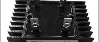
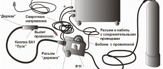
Converters that use a semiconductor diode bridge are widely used both in electrical engineering (for example, in welding machines, where the rated current can reach up to 500 amperes) and in radio electronics, as a source for low-current circuits.
Note that in addition to semiconductor diodes, you can also use vacuum diodes - kenotrons (an example of a circuit diagram of such a device is shown below).
Scheme: converter based on a 6Ts4P two-anode kenotron
Actually, the presented circuit is a classic implementation of a full-wave balanced converter. Today, vacuum diodes are practically not used; they have been replaced by semiconductor analogues.
WITHOUT A RECTIFIER IS LIKE WITHOUT HANDS
L, 1995, No. 2
First, answer the simple question: “What is the voltage in the network?” Surely most will say; "220 volt". Others will also add: “Variable, 50 hertz.” All this is, of course, true. The voltage (effective) in most lighting systems is 220 V, and it is alternating, sinusoidal, and the frequency of the sinusoidal oscillations is 50 Hz, which corresponds to a repetition period of 20 milliseconds.
Picture 1.
But few people know that the amplitude value of the voltage in the network is approximately 310 V, and the difference (range) between the maximum and minimum values is as much as 620 V (Figure 1a). It is not difficult to calculate the amplitude value - you need to multiply the effective voltage by √2. What does this give? In this way, you can calculate what DC voltage will be obtained from an AC voltage if it is rectified.
This is done using semiconductor diodes (Figure 2a). The diode (it is designated by the symbol VD1) has two electrodes - the cathode (k) and the anode (a). Current through the diode can only pass in the direction from the anode to the cathode (along the “arrow” of its graphic image). On the reverse side, almost no current flows through the diode (especially if it is silicon) - they say that then the diode is “closed”.
Figure 2.
To ensure the most perfect rectification - full-wave, four (VD1 - VD4) diodes are combined into a so-called bridge circuit (Figure 2b). But there are also ready-made diode bridges - Figure 2c shows one of them - VD1.
A bridge double-wave rectifier works like this.
Let's imagine an ordinary incandescent lamp HL1 with a voltage of 220 V. Then, according to the diagram in Figure 3a, it will shine approximately the same as if there were no diodes VD1 - VD4 at all. After all, when the voltage polarity shown in Figure 3b operates in the network for 10 ms, the current will flow through diode VD1, lamp HL1 and diode VD4. When, within another 10 ms, the polarity of the voltage in the network changes to the opposite (Figure 3c), current will flow through VD3, pump HL1 and diode VD2. In other words, now the current through the HL1 lamp always flows in the same direction, and not in different directions, as in Fig. 1 in AC network. But for an incandescent lamp it seems to be indifferent - its filament heats up equally, no matter in which direction the current flows. The heating will be the same if we apply voltage to the lamp according to the graph in Figure 1a (alternating voltage with a frequency of 50 Hz) or according to the graph in Figure 1b (pulsating voltage with a frequency of 100 Hz).
Figure 3.
If you now connect an oxide (electrolytic) capacitor C1 in parallel with the lamp (in Figure 3d), lamp HL1 will flash much brighter. After all, the supply of electricity in capacitor C1 is almost enough to compensate for the decrease in voltage during the “intermissions” between individual ripples. Consequently, the voltage on capacitor C1 will be close to the amplitude value of 310 V (Figure 1c). During such an experiment, our light bulb may simply burn out!
We will assume that our experiment is purely speculative - it is unlikely that you will need such a high voltage (310 V!), which, meanwhile, was popular in lamp technology. Now transistor and microcircuit technology deals with voltages 10...50 times less. Yes, this is good - this level is already quite safe.
Let's reduce the voltage in the usual way - using a step-down transformer T1 (Figure 4). It can be incandescent from an old tube TV. If 220 V is applied to the primary winding I, then the voltage on the secondary winding II will be approximately 7.5 V. We already know that this is the effective voltage value. This means that the amplitude value should seem to be 1.41 times greater, and will be approximately 10.5 V. But on capacitor C1 it will actually be somewhat less, namely about 9 V. The fact is that until now we conventionally did not take into account the voltage drop across two “open” diodes. And it is neither more nor less - approximately 1.4 V (for silicon diodes). Therefore, in reality we will get a constant voltage of about 9 V. And our mains rectifier can act as batteries “Krona”, “Korund”, “Oreol-1” or a battery 7D-0, 115-U1.1. From such a rectifier it is quite possible to power a small receiver, a small player...
Figure 4.
To connect to the network, the rectifier uses a regular XP1 plug (Figure 4). The equipment is connected to it using an XS1 socket, which is taken from an old Krona battery. Oxide capacitor C1 can be of any type: the larger its capacity, the better, the less ripple the rectified voltage will be. Diode bridge VD1 can be taken with any letter index from diode assemblies of the KTs405, KTs402 series. If there is no ready-made assembly, it is replaced with a bridge assembled from four diodes. The most suitable diodes for such a replacement are the KD105 or KD208, KD209 series. But you can also use the modern KD226 series or use the D226 series diodes that were popular in the past. If you take germanium rather than silicon diodes, the rectified voltage will increase to almost 10 V, which, however, is quite acceptable for the equipment. The resulting “additive” is explained by the fact that germanium diodes have a lower forward voltage drop (about 0.4 V for each diode) than silicon diodes (about 0.7 V). It is quite possible that avid radio amateurs may have such diodes lying around, and they will share them. Old diodes of the D7 series (for example, D7Zh, D7E) will work very well. But the more ancient ones are also suitable - DGTs-24, DGTs-25, DGTs-26, DGTs-27.
Do not forget to check the diodes for serviceability before assembly; this is especially important if you got them by accident. You can check them in different ways, but the best way to do this is with an ohmmeter. In one direction, the diode (especially if it is germanium) will have a very small resistance, and in the other direction, on the contrary, it will have a very large resistance (if it is silicon).
V.VASILIEV
How to organize bipolar power supply
By combining a balanced circuit and a bridge circuit, you can get a converter that will provide bipolar power at the output with a common (zero) point. Moreover, for one it will be negative, and for the other it will be positive. Such devices are widely used in power supplies for digital radio technology.
Diagram: example of a converter with bipolar output
How to implement voltage doubling
Below is a circuit that allows you to obtain a voltage at the output of the device that is twice as high as the original one.
Voltage doubling circuit
It is typical for such a device that two capacitors are charged in different half-cycles, and since they are located in series, then, as a result, the total voltage at “Rn” will be twice as high as at the input.
In a converter with such a multiplier, transformers with a lower secondary winding voltage can be used.
DC voltage oscillogram
Let's first clarify what we mean by “constant voltage”.
As Wikipedia tells us, constant voltage (also known as direct current) is a current whose parameters, properties and direction do not change over time. Direct current flows in only one direction and its frequency is zero. We looked at the DC oscillogram in the article Oscilloscope. Operating Basics:
As you remember, on the graph we have time voltage vertically (Y-axis).
In order to convert a single-phase alternating voltage of one value into a single-phase alternating voltage of a smaller (possibly larger) value, we use a simple single-phase transformer. And in order to convert it into a constant pulsating voltage , we connected a Diode Bridge after the transformer. The output received a constant pulsating voltage. But with such tension, as they say, you can’t change the weather.
But how can we get out of the pulsating constant voltage
get the most real constant voltage?
To do this, we need just one radio component: a capacitor. And this is how it should be connected to the diode bridge:
This circuit uses an important property of a capacitor: charging and discharging. A capacitor with a small capacity charges quickly and discharges quickly. Therefore, in order to get an almost straight line on the oscillogram, we must insert a capacitor of decent capacity.
Using Op Amps
As is known, the current-voltage characteristic of diodes is nonlinear; by creating a single-phase precision (high-precision) full-wave rectifier on an op-amp chip, the error can be significantly reduced. In addition, it is possible to create a converter that allows you to stabilize the current on the load. An example diagram of such a device is shown below.
Circuit: a simple op-amp stabilizer
The figure shows a simple current stabilizer. The op amp used in it is a voltage controlled source. This implementation makes it possible to ensure that the current at the output of the converter does not depend on the voltage loss across the load Rн and the diode bridge D1-D4.
If voltage stabilization is required, the converter circuit can be slightly complicated by adding a zener diode to it. It is connected in parallel to the smoothing capacitance.
4.10. AC current and voltage rectification
Let's look at the operation of several simple rectifiers
Operation of a half-wave rectifier on an r-load
Let the circuit be given (Fig. 4.47), the current-voltage characteristic of the diode (Fig. 4.48) and the source voltage u(t) = Um sint. Let's set the task: determine the current in the circuit and the voltage across the load. We use the graphical method to calculate the current.
Graphic constructions are simple and clear (Fig. 4.48). When the source voltage is sinusoidal, the current in the circuit is non-sinusoidal. It can be seen that the current is unipolar. If this current is multiplied by the resistance (r), we get the voltage across the load. If we neglect the shaded area, then in the interval (p – 2p) the current will be zero (Fig. 4.49).
Let's determine the average value of the rectified current:
.
For comparison, the average value of the sinusoidal current is:
.
The effective value of the rectified current is equal to:
.
It can be seen that the effective value of the rectified current is several times less than that of alternating current.
With the accepted assumptions, the efficiency of this rectifier is:
,
Where
.
Then finally:
Operation of a half-wave rectifier on an rL-load
Let's introduce inductance into the circuit (Fig. 4.50) and solve the same problem.
Given: u = Um sinwt, L, r, BAX. Let us determine the current i., and voltage ur.
Let us apply the piecewise linear approximation method. We begin the calculation from time t = 0. At this moment, the diode opens and its resistance becomes zero.
The problem is solved in the same way as when calculating the transient process.
We will not give the solution here; we will only give the final expression for the current:
.
The first term in this expression is the free component, and the second term is the forced component, which is calculated according to the substitution scheme (Fig. 4.51) using the complex-symbolic method. We find the integration constant A from the initial conditions:
.
Where:
.
The expression for the current will take the form:
,
where p = -r/L.
Let's plot this current (Fig. 4.52, dashed line). The solution for the current is valid as long as the current is greater than zero i(t) > 0. As the inductance increases (Fig. 4.53), the ampere-second area does not change, but only deforms.
Using an L-element in a half-wave rectifier to improve the quality of the rectified current makes it possible to reduce the amplitude factor Ka, but does not provide ideal rectification of alternating current.
Operation of a half-wave rectifier with an rC load
Let's introduce capacitance C into the half-wave rectifier circuit, connected in parallel with the load (Fig. 4.54). We will also begin the calculation from the moment the diode is unlocked. Let us apply the piecewise linear approximation method.
Let at some point in time t1 the operating point on the diode characteristic move to the first quadrant, the condition is satisfied: ja>jк.
The diode resistance becomes zero: .
The source voltage becomes equal to the voltage across the capacitor and the load:
.
The current is:
In circuits with a capacitor, when first switched on to voltage, incorrect switching is observed, which is accompanied by large current surges. If C > 1000 µF, the rectifier must be protected from these surges.
At the point in time when the input voltage reaches its maximum value:
,
The cathode potential becomes greater than the anode potential: jк > ja. In this case, the key (diode) opens. The capacitor discharge can be described by the equation (Fig. 4.55):
.
the charge will continue as long as the voltage on the capacitor is greater than the input voltage: uc(t) > u(t). The effect of the capacitance size on the discharge rate of the capacitor is shown in (Fig. 4.56). The use of a capacitive element connected to the load of a half-wave rectifier makes it possible to smooth out the rectified voltage and perform the task in a certain load range.
Single-phase rectifier circuits
Let's look at the most common single-phase rectifier circuits.
1.
Full-wave rectifier (Fig. 4.57).
Given: voltage, resistance Rн, diodes 1, 2, 3, 4 and their current-voltage characteristics.
It is required to determine Un and in.
Let us analyze the circuit using the piecewise linear approximation method. We begin the calculation from time t = 0.
The top clamp becomes positive. A current flow path is formed. Diodes 1 and 2 are unlocked. The voltage across the load is:
When the input voltage becomes less than zero: Diodes 1 and 2 are locked, and 3 and 4 are unlocked. The load voltage becomes equal to:
.
Subsequently, the processes are repeated. Timing diagrams are shown in (Fig. 4.58).
Let's analyze the effect of C-elements on the output voltage curves (Fig. 4.59). With full-wave rectification, the quality of the rectified voltage can be ensured by smaller values of reactive elements. The main disadvantage of this rectifier is that the rectified voltage level depends on the input voltage.
2.
This drawback is not present in the circuit (Fig. 4.60), since using a transformer you can obtain any voltage on the secondary winding by changing the transformation ratio.
The transformation coefficient is equal to:
.
By choosing a CT, you can form any U2:
The processes in the circuit (Fig. 4.60) are completely similar to the previous one (Fig. 4.57), where diodes 1 and 2 were turned on, diode 1 will be turned on here.
Using a transformer element, the input circuit with voltage U1 is galvanically isolated from the output circuit with voltage Un.
If some point of the output circuit is connected to ground, then the electromagnetic pulse entering the input circuit will not lead to a redistribution of potentials in the output circuit. An electromagnetic pulse can be a lightning discharge, a welding arc, sudden short circuits or breaks in the circuit.
An electromagnetic pulse propagates wirelessly and is induced into an electrical circuit thanks to reactive elements.
Three-phase rectifier circuits
Consider a half-wave three-phase rectifier (Fig. 4.61). The initial information for calculations is specified in the same way.
Given: input phase voltage, load resistance Rн, diodes 1, 2, 3 and their current-voltage characteristics.
Determine the load voltage un.
Let's start calculating this rectifier from the moment in time. From this moment on, the voltage is greater than all other voltages, so the load voltage is equal to:
.
From a moment in time, the tension is greater than all others. Therefore the load voltage is:
.
Further calculations are clear, and the timing diagram is shown in (Fig. 4.62). The output voltage curve is unipolar, it fluctuates from the amplitude value to half of it. With this voltage it is already possible to power loads such as a DC motor, which has a small dependence of the rotation speed on the pulsation coefficient.
Consider a three-phase full-wave rectifier (Fig. 4.63, Larionov circuit).
The circuit (Fig. 4.63) works similarly to the previous one (Fig. 4.61).
In the interval of points 1 – 2 (Fig. 4.64), the voltage curve uc is inverted. Therefore, the output voltage uн has an even lower ripple coefficient compared to the circuit (see Fig. 4.62).
For most general technical installations, this curve meets the standards and does not require additional filtering.
Qualitative indicators of the output voltage of rectifiers
The main indicator of the quality of the output voltage is the ripple factor, which is equal to the ratio of the difference between the maximum and minimum values of the output voltage to its nominal value:
.
The next indicator is the distortion factor, which is equal to the ratio of the effective value of the first harmonic voltage to the effective voltage value:
.
The harmonic coefficient evaluates the content of higher harmonics in the voltage and is equal to the ratio of all higher harmonics to the fundamental harmonic:
Efficiency:
.
Power factor:
Distortion Power:
.
Briefly about controlled converters
It is often necessary to control the voltage at the output of the converter without changing the input. For this purpose, the most optimal would be to use controlled valves; an example of such an implementation is shown below.
Simple thyristor converter (on controlled valves)
Three phase rectifier
We looked at various implementations of single-phase full-wave converters, but similar devices are also used for three-phase sources. Below, as an example, a device created according to Larionov’s scheme is shown.
An example of the implementation of a Larionov circuit Oscillogram at the output of a Larionov circuit
As the graph above shows, the implementation of a bridge circuit between pairs of phases allows for minor ripples to be obtained at the output. Thanks to this, the filter capacity can be significantly reduced, or even dispensed with.
Design
Calculating even a simple full-wave converter is not an easy task. It can be significantly simplified using special software. We recommend choosing the Electronics Workbench program, which allows you to perform schematic modeling of analog and digital electrical devices.
By simulating a full-wave rectifier in this program, you can get a clear idea of the principle of its operation. Built-in formulas allow you to calculate the maximum reverse voltage for diodes, the optimal capacity of the quenching capacitor, etc.
Classification by purpose and device
AC rectifiers are divided into several different types, depending on the characteristics, the use of alternating current periods, circuits, the number of phases and the type of transmitting element. In general, the classification is as follows:
- By the number of periods involved in the work (one- and two-half-wave, as well as with full and incomplete use of the wave);
- By type, devices are divided into those that include an electronic bridge, voltage multipliers, with or without transformers;
- Based on the number of phases, they are divided into single-phase, two-phase, three-phase and N-phase;
- According to the type of device that transmits a sine wave, they are divided into semiconductor diode and thyristor, mechanical and vacuum, mercury;
- Based on the type of transmitted waves, they are divided into pulsed, analog and digital.
Useful tips Connection diagrams Principles of operation of devices Main concepts Meters from Energomer Precautions Incandescent lamps Video instructions for the master Testing with a multimeter