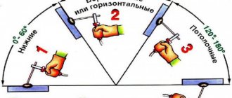
ASCON has released the KOMPAS-3D V16.1 update and three configurations for it. In the mechanical engineering configuration, truly revolutionary changes have occurred in the applications of Pipelines, Shafts and Mechanical Transmissions, and Welded Joints. The AC/AP Architecture application from the Building Configuration has learned to read the IFC format. Cables and harnesses from the Instrument-Making Configuration build routes up to 10 times faster. And all these updates are available free of charge to all users of KOMPAS-3D V16.
So, what new items await you after installing the update.
The basic configuration of KOMPAS-3D V16.1 includes bug fixes, as well as improvements implemented based on user suggestions. In particular, the work of specifications with multi-sheet documents has been improved. Now in the Note column either the formats and numbers of sheets can be indicated: 2xA4, 2xA3, or only the formats: A4, A3. Improved preview mode. Drawing views in the preview window can now be displayed in a simplified manner - as dimensional rectangles. This speeds up the rendering of drawings when you go to preview, especially if the number of sheets is large or the views are saturated. Recording in pdf format has been improved: you can select the boundaries of the saved document; in addition, it now includes the properties of the original KOMPAS document.
Designation of seams of welded joints in Compass-3D
For the attention of advanced students and engineers, a program is presented to facilitate the designation of welds on drawings in Compass-3DV 13 and higher.
Essentially, it is a library. To get started with it you need to do the following:
1. Download the program file in the archive here;
3. Without starting Compass-3D, install the program that you have already downloaded;
5. Create a new 2D document, for example “Drawing”.
6. Go to the following path: “View” -> “Toolbars” -> “Welding”. Click on “Welding”
7. The following toolbar will appear:
8. Enjoy it for your health!
Catalog: Welds. Mechanical engineering application for KOMPAS-3D
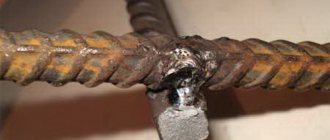
If a model or drawing of a welded structure is saturated with different welds, it is quite difficult not to make mistakes when designing or editing weld symbols. Catalog: Welded seams will help simplify the placement of designations in the model and avoid errors when indicating the numbers and number of seams in the drawing. The catalog consists of the following applications:
Equipment: Welded joints
- Designation of a seam and indication of its symbol directly in the model. The created symbol is automatically transferred to the drawing of the welded structure. In addition, the length of the weld can also be transferred to the drawing. The following methods are available for creating a symbol in the model: by edges (in this case, the edges of the first and second objects are indicated alternately to construct a weld seam between them); along the edges (the seam is constructed along the edges specified in the model); by points (a symbol for resistance welding is created);
- Quick designation of weld seam designations according to GOST is possible due to the dialog box in which you can select welding parameters (standard, type, method, etc.). When you enter a new seam designation into the current document, the next serial number is automatically entered. It is possible to insert a designation from a custom template (a set of commonly used stitches).
- The ability to create designations for welds in drawings in accordance with the standards GOST 2.312-72, ISO 2553:1992 (DIN 22553-1997), create tables of welds.
- Checking the designations of welds of the current document according to GOST before automatically constructing a table of welds in accordance with the selected style. Checking allows you to avoid inconsistencies in the types of symbols in the drawing, the number of seams and their numbers. You can select the style of the weld table from the list provided or create it yourself.
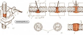
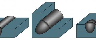
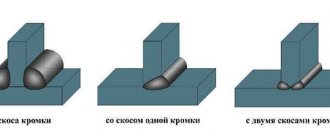
- Inserts weld seam structural elements into a drawing or sketch of a model. In the dialog box, by selecting the parameters of the desired connection, you can insert an image of a seam or the cutting of its edges. Images of structural elements of seams are available in accordance with GOST 5264-80, GOST 8713-79, GOST 14771-76, GOST 14806-80.
Symbols for welded joints
- Indication on the drawing of the image of the legs of the welds and the designation of the seams in accordance with GOST 21.502-2007.
- Ability to configure the type of leg (equilateral or unequal) and the direction of rounding (inward or outward). It is possible to draw the leg without rounding - in the form of a triangle.
- Select the type of seam when inserting its image into a document in accordance with GOST 21.502-2007: factory or assembly, continuous or intermittent - and indicate whether the seam line should be visible or invisible. Geometric parameters of seam images (length of strokes, distance between strokes and groups of strokes, type of lines, etc.) are configured by the user.
Requires: KOMPAS-3D Manufacturer: ASCON
Where can I buy? Ask a Question
Construction configuration
The main novelty of KOMPAS-3D V16.1 for designers is reading the IFC format in the Architecture: AC/AP application through the development and optimization of the converter of this format. This allows us to establish a close relationship between the Renga Architecture BIM system and the MinD design technology: now it is possible, based on the 3D model data, to obtain ready-made plans from Renga and fill them with sections KM, OV, VK, TX and others, which designers perform in the KOMPAS construction applications 3D.
In the applications Technology: TX, Life Support: VK and Life Support: OV, new pipe catalogs have been added and the function of selecting a material grade depending on the assortment has been implemented, which significantly expands the range of application applications when designing the corresponding sections.
The Gas Supply: GSN application has undergone major changes. It introduced the ability to generate tables of coordinates of rotation angles and picket coordinates, as well as the ability to place both a profile and a plan on one sheet. And by the way, now you can combine two profiles into one profile and draw additional elements on the profile, taking into account the presence of the second side of the pipe.
In the Rubius Electric Suite: 0.4-10 kV power lines application, the construction of a list of intersections with engineering objects has been implemented and the module for calculating voltage losses has been improved.
Weldment callout
Button Permanent connections - calls the GraphiCS SPDS tool for drawing and inserting a welded joint leader into the drawing.
To call the Permanent Connections tool, you can use the following methods:
- click on the icon on the SPDS tab - Notation panel;
- click on the icon on the Welding panel;
- Menu bar - SPDS - Welding - Permanent connections;
- enter the spfix command into the command line.
To draw and insert a weldment leader:
- activate the function (click on the icon or enter a command into the command line);
- use the mouse to indicate the location of the permanent connection;
- indicate the break point of the leader line or complete the entry;
- specify the end point of the leader line;
- in the Permanent connections dialog box, configure the type of connection (on the Simplified image or Full image tab).
On the Simplified Image tab, select the type of permanent connection. If the Full Image tab is available to you, switch to it and configure the permanent connection designation.
To automatically count the number of identical welds in a drawing, place the cursor in the input field and click the left mouse button. In the dialog that opens, enter the number of the weld and press the button.
Only after this will an automatic count of all welds with this number in the drawing be made:
In order to edit the text fields for the designation of a permanent connection, you must left-click in the corresponding part of the full image, as a result an input dialog will appear.
The following auxiliary commands are also available in the context menu of the text field of this dialog box:
- list of frequently used symbols;
- Story;
- The Take from Drawing command allows you to copy values from drawing objects;
- inserting Symbols from a list or from a complete symbol table;
In the value editing dialog, buttons for quickly inserting special symbols for designating a welded joint are additionally available:
Thanks to pop-up tips that explain the meaning of a particular symbol on the buttons, working with the tool becomes much more convenient.
The Copy Properties button allows you to copy properties from a dimension already existing in the drawing.
Edit dialog control buttons:
— Close the dialog, saving changes (OK)
— Close the dialog without saving changes (Cancel)
By clicking the left mouse button in the corresponding part of the full image, you can turn on or off additional graphic elements in the designation:
On the Simplified tab of the Permanent Connection dialog box, two additional buttons are available at the bottom of the window:
— Arrange the weld points. Designed for marking weld points on the drawing.
- Along a closed circuit. Designed to add a "closed loop" symbol to a connection designation.
Editing a weld joint leader is done using the editing handles:
- double-click on the symbol with the left mouse button;
- right-click on the symbol;
- select the designation and right-click to open the context menu, in which select Edit;
- activate the Editing function and point to the designation;
- use the AutoCAD Properties window;
- using the editing handles.
In this lesson you learned about the GraphiCS SPDS tool, you can draw a weld joint leader. This tool will help you speed up and optimize the process of completing and preparing drawings.
source
Symbols on the drawing in KOMPAS 3D – StroyMetProekt
Home » Tutorial » KOMPAS 3D training » Symbols on a drawing in KOMPAS 3D
Creation of cross-section symbols is carried out through the menu Tools → Symbols → Cut line or using the Cut line command on the Symbols toolbar. At the beginning of the command, you must select the point to place the first symbol of the cut arrow. Then you need to determine what type of cut will be shown - simple or complex (with a broken cut line). If you intend to show a simple cut, then you must then indicate the point of placement of the second cut arrow symbol. If you intend to show a complex section, then you must first click the Complex section button and sequentially indicate the placement points of the bends of the complex section. The second cut arrow symbol will always be placed at the last point. To complete entering a complex section, press the Complex section button.
Next, you should enter the letter designation of the section, if it is not set automatically. When you click the Text field, the Enter Text dialog box appears. In which you can manually fill in text fields. The first field is the letter designation of the section. The second field is additional information (for example, the number of the sheet on which the cut is located).
If you check the Auto sort option, the program will automatically assign a symbol to indicate the section. This option may not be available if in the Tools → Options menu on the Current Document tab, in the Auto Sort section, the Auto Sort option is unchecked. Enabling the Sheet and Zone options automatically places the sheet number. Where the incision is placed. Or zone designation in the additional field of the section symbol. Using the Placement group of buttons, you can set the placement of additional information at the first or second arrow of the section.
After these operations, it is necessary to choose the direction of view of the incision. To do this, move the mouse across the cut line in one direction or another. you need to achieve the desired location of the gaze arrows and press the left mouse button or the Enter key.
Then the program offers to place a letter designating the view with a section. In this case, it is proposed to configure 2 tabs: on the Parameters tab, settings are made for the parameters of the new sectional view, and on the View Designation tab, settings for the text commentary for the sectional view are made.
- — Cut line command
- — Button Complex cut
- — Buttons Placement
| Parameter | Description |
| Number | This field specifies the type number - this is a unique number that is assigned automatically by the system. But it is possible to enter it manually. The program will not allow you to create 2 types with the same number |
| Name | This field specifies the name of the view - this is any phrase that does not have to be unique. The name of the view is displayed in the drawing construction tree, displayed by the command View → Construction Tree |
| Color | This drop-down graphical menu allows you to select the color of the view elements. For each type you can assign your own color. The color of the elements of the current view appears when switching from the current view to another view in the drawing tree. It is displayed by the command View → Construction tree. Switching is done by using the right-click menu on the desired view and selecting the Current command. The current view is marked with the letter (t) in the drawing tree |
| View scale | This formatted drop-down menu field specifies the scale of the view. In this case, all elements of the drawing are visually reduced or increased in accordance with the scale, but their actual dimensions do not change |
| View point | Using this group of buttons, you set the position of the base point of the view: In the center of the outline rectangle or At the origin of coordinates of this view |
| Anchor point | These coordinate fields indicate the view's anchor point. This is the point that coincides with the base point of this view |
| Corner | This field specifies the angle of inclination of view elements around the base point relative to the global coordinate system |
| Parameter | Description |
| View Notation View Window | This graphics window displays all view symbol settings |
| Insert link | Using this button, you can select the letter designation of a section/section line existing in the drawing. By default, the link is created automatically by the program |
| Letter designation | Enabling this option allows you to display the view's letter designation. With a cut/section in the “A-A” format. Attention - turning off this option makes this option unavailable for turning back on! To enable display of the view letter designation, you must:
|
| Expanded | Enabling this option allows you to display the Expanded icon in the view letter. This icon is used to indicate an expanded view |
| Scale | Enabling this option allows you to display a scale value icon in parentheses (e.g. "1:2") in the view symbol |
| Rotated | Enabling this option allows you to display the Rotated icon in the view letter. This icon is used to indicate an expanded view |
| Corner | Enabling this option allows you to display the view rotation angle value in the view letter. This option becomes available when the Rotated option is enabled. In the case when there is a projection relationship between the section view and the reference view with section arrows (on the Parameters tab). Then the Rotated icon is not displayed in the view letter. It should be noted that the creation of this projection link is only possible in the 3D model design mode |
| Sheet | Enabling this option allows you to display the number of the sheet on which the section arrows are located in the letter designation of the view |
| Zone | Enabling this option allows you to display the designation of the zone in which the section arrows are located in the letter designation of the view |
Creating a view arrow symbol is done through the menu Tools → Notation → View Arrow or using the View Arrow command on the Notation toolbar. At the beginning of the command, you need to select the location point for the first symbol - the view arrow. Next, you should enter the letter designation of the type, if it is not installed automatically.
When you click on the Text field, the Enter Text dialog box appears, in which you can manually fill in the text fields:
- The first field is the letter designation of the type
- The second field is additional information (for example, the number of the sheet on which the view is located).
If you check the Auto sort option, the program will automatically assign a symbol to indicate the type. This option may not be available if in the Tools → Options menu on the Current Document tab, in the Auto Sort section, the Auto Sort option is unchecked.
Enabling the Sheet and Zone options automatically places the sheet number (on which the view is located) or the zone designation in the additional field of the view symbol.
After these operations, it is necessary to select the direction of viewing the view. To do this, by moving the mouse around the pointer point, you need to achieve the desired location of the gaze arrow and press the left mouse button or the Enter key.
- — Team Sight Arrow
Then the program prompts you to place a letter designating the species. In this case, it is proposed to configure 2 tabs:
- On the Parameters tab, settings for the new type of parameters are made
- On the View Designation tab, settings for the text commentary for the view are made.
These options are the same as the section view options.
The creation of callout symbols is carried out through the menu Tools → Symbols → Detail or using the commands, Detail on the Symbols toolbar. To do this, you first need to select the center point of the bounding circle in the reference view to enclose the extensions. Then you need to specify the second point - the boundary of the circle. It can also be entered in the options bar in the circle diameter or radius field, depending on the button pressed. Next, you should enter the letter designation of the view for the detail element, if it is not set automatically.
When you click the Text field, the Enter Text dialog box appears, allowing you to manually fill in the text fields. The first field is the letter designation of the view for the detail element, the second field is additional information (for example, the number of the sheet on which the view is located). If you check the Auto sort option, the program will automatically assign a symbol to indicate the type. This option may not be available if in the Tools → Options menu on the Current Document tab, in the Auto Sort section, the Auto Sort option is unchecked. Enabling the Sheet and Zone options automatically places the sheet number (on which the view is located) or the zone designation in the additional field of the view symbol for the detail element.
- — Command Detail
- — Fields diameter and radius
After this, you need to set additional parameters for the callout symbol on the Options tab. On this tab you can select the following options:
- drop-down menu Shape with options Circle, Rectangle or Rounded Rectangle - specifies the shape of the bounding element in the reference view;
- Shelf drop-down menu with options Left, Right, Up or Down—specifies how the detail detail symbol will be placed on the reference view;
- Default option - the enabled option allows you to use the parameters of this symbol (shape type, etc.) to create a new detail symbol in the reference view.
Good job!)
stroymetproekt.ru
Lesson 12. Welded joint drawing
Hello, friends! We continue the topic of creating assemblies in Compass, and today we will create an assembly drawing of a welded joint for the product Support.
Let's take the initial task from Bogolyubov's textbook, 1985, p. 285.
Creating an Assembly
To create an assembly, you need to make 3 d models of all the parts included in it.
You can create the details yourself or download them from the link at the end of the article.
For each part, add a specification object: Specification→Add object→Details→Create.
Create an assembly: XYZ orientation, insert the Plate first, then the Cylinder and Eye. Learn more about creating an assembly and applying mates.
Then we create specification objects for the assembly: Specification → Create specification objects.
Now a new document has appeared in the folder with assembly documents - a specification containing information about the components of the assembly.
Assembly drawing of a welded joint
Let's create an associative assembly drawing of the product Support.
Turn off the left view of the product and insert two views into the field of the A4 drawing.
As you can see, the views are too bulky, so let's set the scale for them to 1:2. Select them, in the context menu (RMB) select the Scale command, select 1:2.
The front view should be replaced by a frontal section, so we delete it.
This cut needs to be adjusted because the eyelet should not be shaded.
Call the Drawing Tree window: View→Drawing Tree. We get to the Eyelet component and in the Context menu select the Don’t cut command. Rebuilding the assembly
It is also necessary to remove the letter designation of the cut and the trace of the cutting plane. To do this, we create invisible layers to which we transfer these designations.
Working with specifications
Now we arrange the positions of the parts in the drawing arbitrarily; we will edit them later.
To edit positions in a welded joint drawing, you need to link it to a specification file. Open the specification and call the Assembly Management window
→click “+” Connect document and add a link to the assembly drawing.
Synchronizing positions
In order for the positions on the drawing and the specifications to be the same, we synchronize them.
We leave open only the files of the drawing of the welded joint and the specifications for it. In the Window menu, select the Mosaic window arrangement vertically. On the assembly drawing, select the position of the Ear and select the corresponding line in the specification. Next, click on the Edit object composition button→select assembly drawing→Add.
We repeat the procedure for all positions, and the positions in the drawing are renumbered automatically.
It is necessary to add a Documentation section to the specification, and an assembly drawing to it. Click the Add section button, select the Documentation - Create section. On the properties panel, select the Documents tab and load the assembly drawing. We agree to take the data from the title block.
Let's do one more important thing - add links to the part models we created to the specification items. Once added, indicating the position of the part in the specification, the Compass will highlight this part in the drawing. This is very convenient when working with large assembly drawings.
To do this, select the position of the slab in the specification → on the properties panel, click the Documents tab → “+” Add document → select the file with the slab model → add a link. For the remaining parts we proceed similarly.
Now, by clicking on the Show object composition button
and highlighting the line with the position of the part, this part will be highlighted in green in the drawing.
At this point, work on the specification can be completed.
It remains to finalize the assembly drawing of the welded joint of the support.
We draw axial lines, indicate dimensions, surface roughness and mark welds.
Designation of welds in the drawing.
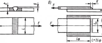
The cylinder, eye and plate are connected by a standard T-weld, where the end of one part is connected to the side surface of another part.
To indicate such a seam, a callout with an arrow having one notch is used. The designation includes GOST for the seam, the type of seam, the sign indicating the size of the leg and the size itself.
On the conventional image of the seam connecting the cylinder to the plate, a seam symbol is added along a closed line.
final drawing of the welded joint looks like this.
source
KOMPAS-3D V16.1: welding in 3D, 10-fold increase in speed in Shafts and completely new Pipelines
ASCON has released the KOMPAS-3D V16.1 update and three configurations for it. In the mechanical engineering configuration, truly revolutionary changes have occurred in the applications of Pipelines, Shafts and Mechanical Transmissions, and Welded Joints. The AC/AP Architecture application from the Building Configuration has learned to read the IFC format. Cables and harnesses from the Instrument-Making Configuration build routes up to 10 times faster. And all these updates are available free of charge to all users of KOMPAS-3D V16.
So, what new items await you after installing the update.
The basic configuration of KOMPAS-3D V16.1 includes bug fixes that were previously provided as Express updates, as well as improvements implemented based on user suggestions. In particular, the work of specifications with multi-sheet documents has been improved. Now in the Note column either the formats and numbers of sheets can be indicated: 2xA4, 2xA3, or only the formats: A4, A3. Improved preview mode. Drawing views in the preview window can now be displayed in a simplified manner - as dimensional rectangles. This speeds up the rendering of drawings when you go to preview, especially if the number of sheets is large or the views are saturated. Recording in pdf format has been improved: you can select the boundaries of the saved document; in addition, it now includes the properties of the original KOMPAS document.
Mechanical Configuration
The Equipment: Pipelines application has been completely updated. Users received more design capabilities and freedom, getting rid of the unpleasant features and limitations of the previous version. Modeling pipelines has become more convenient, clearer, simpler and faster. A new, extensive catalog has appeared, thanks to which pipes, pipeline parts, shut-off and control valves are selected directly in the application. And the almost omnipotent “Pipeline” command - using a 3D manipulator, we simply lay a pipe from point A to point B. If the pipe path makes a turn, a bend from the catalog is automatically installed at this place, or the pipe is bent with a given radius. If three pipe segments meet, a tee or insertion automatically appears at their intersection.
In the Shafts and Mechanical Transmissions 3D application, the gear generation module has been redesigned, so that 3D gear models are now built 10 times faster. A module has been developed for generating geometrically correct models of ring gears of worm wheels and bevel wheels with a circular tooth. The correctness of the construction of the models is confirmed by industrial tests of the module. The Kazakh ZincMash, which produces equipment for mining, processing and metallurgical industries, acted as a test site. The manufactured worm wheels are currently used in equipment units manufactured at the enterprise.
A module has been developed for generating realistic threads of all types, providing the construction of not only profiles, but also the output of threads.
Another long-awaited new product is 3D welding. Application Equipment: Welded Joints now has the ability to create a weld symbol in the model. The created symbol can be transferred to the drawing. The length of the weld can also be included in the drawing. But we won’t stop there; welding in 3D will continue its logical development.
The “Structural elements of welds” command has been added to create images of standard structural elements of welded joints in graphic documents and sketches of KOMPAS-3D three-dimensional models.
In the new version of the Equipment: Reamers application, users will be able to generate a program for cutting reamers on gas, plasma and laser cutting machines with various computer numerical control (CNC) systems, which are configured through the CNC service tools menu.
Instrumentation configuration
In the Equipment: Cables and Harnesses application, the ability to construct routes only using 3D curves selected in the model has been added, and these curves can be combined into macroelements. This will reduce the time for constructing routes from 2 to 10 times, depending on the number of trajectories. A command has been added to the application toolbar to call functions for constructing a 3D frame - a built-in tool for creating parametric trajectories of harnesses.
The eCAD-KOMPAS Converter now has a function for placing positional designations of components in a drawing on associative projection views of 3D models of printed circuit boards. The transfer of 3D models and text data from the domestic end-to-end electronics design system Delta Design of the EREMEX company has been implemented.
Construction configuration
The main novelty of KOMPAS-3D V16.1 for designers is reading the IFC format in the Architecture:AS/AP application through the development and optimization of the converter of this format. This allows us to establish a close relationship between the Renga Architecture BIM system and the MinD design technology: now it is possible, based on the 3D model data, to obtain ready-made plans from Renga and fill them with sections KM, OV, VK, TX and others, which designers perform in the KOMPAS construction applications 3D.
In the applications Technology: TX, Life Support: VK and Life Support: OV, new pipe catalogs have been added and the function of selecting the grade of material depending on the assortment has been implemented, which significantly expands the range of application applications when designing the corresponding sections.
The Gas Supply: GSN application has undergone major changes. It introduced the ability to generate tables of coordinates of rotation angles and picket coordinates, as well as the ability to place both a profile and a plan on one sheet. And by the way, now you can combine two profiles into one profile and draw additional elements on the profile, taking into account the presence of the second side of the pipe.
In the Rubius Electric Suite: 0.4-10 kV power lines application, the construction of a list of intersections with engineering objects has been implemented and the module for calculating voltage losses has been improved.
You will be able to see the work of the updated KOMPAS-3D applications at the events Designer's Day with ASCON and Designer's Day with ASCON.
source
Mechanical Configuration
The Equipment: Pipelines application has been completely updated. Users received more features and design freedom, getting rid of the unpleasant features and limitations of the previous version. Modeling pipelines has become more convenient, clearer, simpler and faster. A new, extensive catalog has appeared, thanks to which pipes, pipeline parts, shut-off and control valves are selected directly in the application. And the almost omnipotent “Pipeline” command - using a 3D manipulator, we simply lay a pipe from point A to point B. If the pipe path makes a turn, a bend from the catalog is automatically installed at this place, or the pipe is bent with a given radius. If three pipe segments meet, a tee or insertion automatically appears at their intersection.
In the Shafts and Mechanical Transmissions 3D application, the gear generation module has been redesigned, so that 3D gear models are now built 10 times faster. A module has been developed for generating geometrically correct models of ring gears of worm wheels and bevel wheels with a circular tooth. The correctness of the construction of the models is confirmed by industrial tests of the module. The Kazakh ZincMash, which produces equipment for mining, processing and metallurgical industries, acted as a test site. The manufactured worm wheels are currently used in equipment units manufactured at the enterprise.
A module has been developed for generating realistic threads of all types, providing the construction of not only profiles, but also the output of threads.
Another long-awaited new product is 3D welding . Application Equipment: Welded Joints now has the ability to create a weld symbol in the model. The created symbol can be transferred to the drawing. The length of the weld can also be included in the drawing. But we won’t stop there; welding in 3D will continue its logical development.
The “Structural elements of welds” command has been added to create images of standard structural elements of welded joints in graphic documents and sketches of KOMPAS-3D three-dimensional models.
In the new version of the Equipment: Reamers application, users will be able to generate a program for cutting reamers on gas, plasma and laser cutting machines with various computer numerical control (CNC) systems, which are configured through the CNC service tools menu.
Weldment callout
Button
Permanent connections - calls the GraphiCS SPDS tool to draw and insert a welded connection leader into the drawing.
To call the Permanent Connections tool, you can use the following methods:
- click on the icon on the SPDS tab - Notation panel;
- click on the icon on the Welding panel;
- enter the spfix command into the command line.
To draw and insert a weldment leader:
- activate the function (click on the icon or enter a command into the command line);
- use the mouse to indicate the location of the permanent connection;
- indicate the break point of the leader line or complete the entry;
- specify the end point of the leader line;
- in the Permanent connections dialog box, configure the type of connection (on the Simplified image or Full image tab).
On the Simplified Image
select the type of permanent connection.
If you have access to the Full image
, switch to it and configure the permanent connection designation.
To automatically count the number of identical welds in a drawing, place the cursor in the input field and click the left mouse button. In the dialog that opens, enter the weld number and click the button
.
Only after this will an automatic count of all welds with this number in the drawing be made:
In order to edit the text fields for the designation of a permanent connection, you must left-click in the corresponding part of the full image, as a result an input dialog will appear.
The following auxiliary commands are also available in the context menu of the text field of this dialog box:
- list of frequently used
symbols; - Story;
- The Take from Drawing command allows you to copy values from drawing objects;
- inserting Symbols from a list or from a complete symbol table;
In the value editing dialog, buttons for quickly inserting special symbols for designating a welded joint are additionally available:
Thanks to pop-up tips that explain the meaning of a particular symbol on the buttons, working with the tool becomes much more convenient.
Copy Properties
button allows you to copy properties from a dimension already existing in the drawing.
Edit dialog control buttons:
— Close the dialog, saving the changes (OK) — Close the dialog without saving the changes (Cancel)
By clicking the left mouse button in the corresponding part of the full image, you can turn on or off additional graphic elements in the designation:
On the Simplified Image
In the permanent connection dialog box, two additional buttons are available at the bottom of the window:
—
Arrange welding points
.
Designed for marking weld points on the drawing. - Along a closed circuit.
Designed to add a "closed loop" symbol to a connection designation. Editing a weld joint leader is done using the editing handles:
- double-click on the symbol with the left mouse button;
- right-click on the symbol;
- select the designation and right-click to open the context menu, in which select Edit;
- activate the Editing function and point to the designation;
- use the AutoCAD Properties window;
- using the editing handles.
source
KOMPAS-3D V16.1: welding in 3D, 10-fold increase in speed on shafts
What new items await you after installing the update.
The basic configuration of KOMPAS-3D V16.1 includes bug fixes, as well as improvements implemented based on user suggestions. In particular, the work of specifications with multi-sheet documents has been improved. Now in the Note column either the formats and numbers of sheets can be indicated: 2xA4, 2xA3, or only the formats: A4, A3. Improved preview mode. Drawing views in the preview window can now be displayed in a simplified manner - as dimensional rectangles. This speeds up the rendering of drawings when you go to preview, especially if the number of sheets is large or the views are saturated. Recording in pdf format has been improved: you can select the boundaries of the saved document; in addition, it now includes the properties of the original KOMPAS document.
Mechanical Configuration
The Equipment: Pipelines application has been completely updated. Users received more design capabilities and freedom, getting rid of the unpleasant features and limitations of the previous version. Modeling pipelines has become more convenient, clearer, simpler and faster. A new, extensive catalog has appeared, thanks to which pipes, pipeline parts, shut-off and control valves are selected directly in the application. And the almost omnipotent “Pipeline” command - using a 3D manipulator, we simply lay a pipe from point A to point B. If the pipe path makes a turn, a bend from the catalog is automatically installed at this place, or the pipe is bent with a given radius. If three pipe segments meet, a tee or insertion automatically appears at their intersection.
The eCAD-KOMPAS Converter now has a function for placing positional designations of components in a drawing on associative projection views of 3D models of printed circuit boards. The transfer of 3D models and text data from the domestic end-to-end electronics design system Delta Design of the EREMEX company has been implemented.
Instrumentation configuration
In the Equipment: Cables and Harnesses application, the ability to construct routes only using 3D curves selected in the model has been added, and these curves can be combined into macroelements. This will reduce the time for constructing routes from 2 to 10 times, depending on the number of trajectories. A command has been added to the application toolbar to call functions for constructing a 3D frame - a built-in tool for creating parametric trajectories of harnesses.
The eCAD-KOMPAS Converter now has a function for placing positional designations of components in a drawing on associative projection views of 3D models of printed circuit boards. The transfer of 3D models and text data from the domestic system of end-to-end electronics design of the company EREMEX has been implemented.