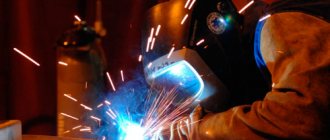
A weld is a section where two parts are joined into a single whole due to the melting of the metal under the influence of high temperature and its further crystallization. Today, more than 100 types of connections are distinguished. They are all divided according to special parameters and divided into various groups and subgroups, and therefore there are many classifications of welds.
According to the type of welded joint
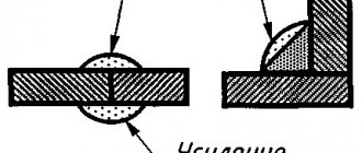
The classification of welds according to the type of welded joint is divided into butt and corner. The master decides which connection to make in a given situation, based on the position of the parts in space.
- Corner welds are made when the workpieces are at an angle to each other.
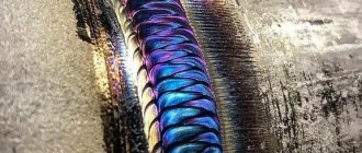
- Welding of butt joints is formed as a result of the adjacency of two parts or parts with their ends facing each other, which are located on the same plane. The track itself can be of three types - concave, convex or flat. The latter is used most often, since it does not have a particularly pronounced transition at the junction of parts, which looks more natural in comparison with the other two types. This method is most often used when electric arc welding at low currents, so as not to scorch the workpiece. For example, sheet steel is an ideal material for butt welding applications.
- Slotted (electric rivet) is made in the hole that is on the part and is made in the form of spot rivets. That is, in this case, a weld pool and a seam are not formed as a result, and the parts are soldered in small sections through grooves in the workpiece.
Differences between welds and joints
A weld and a welded joint are different concepts, but beginners in welding usually confuse these terms. A seam is a place where workpieces meet, which are melted in advance and then cooled. The welded joint consists of three sections that were exposed to high temperature. The latter usually include:
- Seams that appear as a result of melting of the base material. Filler metal may also be added during operation.
- Fusion zone. Geographically, it is located between the weld and the material from which the parts are made. The fusion zone is not subject to high temperatures. It is important to note here that it tends to become saturated with elements that participate in the joining process, electrodes or flux. For this reason, the composition will contain differences from the base metal.
- Thermal affected zone. This is the strip that connects to the fusion zone. At the junction, under the influence of high temperature, the original properties change.
At the place of welding
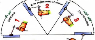
The classification of welded joints and seams in this category depends on the position of the welded parts in space. For example, if you need to repair a part of some kind of structure that cannot be removed and put down, but it is located at some distance from the floor, then the master will carry out the work using a ceiling, bottom, horizontal or vertical connection, starting from the placement of this part.
- Horizontal are welds that extend from left to right (or vice versa) on a vertical part. To prevent the mass of metal from flowing down, it is necessary to correctly select the speed of movement of the electrode or torch and the current strength (this is selected for each case individually, based on the type of welding, the characteristics of the parts and the skill of the specialist).
- The vertical method of producing butt welds is carried out on vertically positioned workpieces, with the seams being made from top to bottom (or vice versa). The complexity of this process lies in the fact that the force of gravity of the Earth is triggered and the molten metal mass flows down all the time, which spoils both the quality and appearance of the part. Such connections are recommended to be carried out in extreme cases and only to those craftsmen who already have a certain theoretical and practical knowledge for working with such paths. More information about vertical seam technology can be found here.
- Ceiling is a position in which the part is located above the master’s head, which greatly complicates the process. When making ceiling welds, you must strictly follow safety rules and welding technology, because in this case the danger lies in the flow of molten metal.
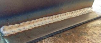
- Lower welding methods are performed when the part is located below in relation to the master. This is the most convenient connection method, since the metal does not spread to the sides or down, but flows into the crater. In addition, gases and slags freely escape to the surface. A butt welded joint in the lower position is performed by forming beads throughout the entire joint of the parts. At the same time, the welding technology is simple - it is enough to move the electrode or torch straight or in a zigzag to create a reliable and aesthetically attractive path.
Types of welding seams
First of all, we need to define another important abbreviation - ESDC. This is a Unified System of Design Documentation, which includes a full range of different standards. They regulate the procedure for the execution of technical drawings, including documentation for welding work.
The system also includes the standards that interest us:
- GOST 2.312-72 . Conventional display options and designations of welding seams in the drawings are prescribed.
- GOST 5264-80 . Comprehensive information is provided on all types of welded joints and seams made by manual arc welding.
- GOST 14771-76 . Detailed information about welding in an inert environment; types of seams and joints obtained under such conditions.
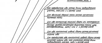
Before studying in detail the examples of designations in the drawings, you need to work out information about their types. This is best done in practice. Let the following image be displayed on the drawing:
A jumble of numbers and incomprehensible symbols does not add optimism in any way. But in reality, not everything is so sad. In fact, such a long line contains a logical chain that is not at all difficult to understand. First you need to break the expression into its component blocks:
It's time to look at all the components, divided into squares:
- an auxiliary symbol that informs a specialist about the type of joint: a closed line or an installation connection;
- number of the standard according to which the symbols are given here;
- letter or number designation of the type of connection with all structural elements;
- method of performing welding work in accordance with the standard;
- type of structural element and its dimensions;
- length of continuous section;
- symbol characterizing the type of connection;
- description of the connection using auxiliary symbols.
Next, we will consider each of the elements of the symbol separately. the first square shows an oval, which symbolizes a circular connection. Its alternative is a checkbox that informs about the installation type of the joint. A one-way arrow indicates the suture line. A specific feature is associated with it, which is expressed in the presence of a shelf. Often on graphic drawings you can see the following sign:
Visually, it is similar to the square root symbol from the field of mathematics. The shelf visible in the figure is a field for placing various symbols about the characteristics of the suture line.
If the information is located under the so-called “shelf”, then this indicates that the weld is located on the back side and is invisible from the front. How do you determine which side is considered front and which side is considered back? With a one-way connection, this is easy to do. The front side will be the side you need to work with. But in a double-sided connection with unequal edges, the front side is considered to be the side on which the main welding joint is located. With identical edges, either side can be front or back.
Below is a table with the most commonly used symbols in drawings and their meanings:
By length
Classification of welds by length is of two types: continuous or intermittent.
- Intermittent is a seam that is made of a certain length with a synchronous interval. It, in turn, is divided into two types - chain track and checkerboard seam. For example, double-sided intermittent joints on one side of the wall are located opposite the welded sections of the seam on the other side. These types of coupling can be either one-way or two-way. That is, the part is soldered on both sides. The distance between these welded sections is called the “welding pitch”.
- Continuous welding methods are also divided into short and long tracks, and are performed along the entire workpiece.
- The spot method of butt welds differs significantly from others, due to the fact that there is no weld pool and track. In this case, the workpieces are connected at points using an overlap weld. This method is often used for soldering thin metal or batteries.
Methods of extended seams: a) continuous b) intermittent, c) point, d) intermittent checkerboard, e) intermittent continuous (chain)
Positions by which classification is carried out
According to regulatory documents, the classification of welding seams has divisions depending on their positions, required length, direction of effort, number of passes, execution features, in particular the number of layers. There are different types of welded assemblies depending on the operating conditions. Finished seams are classified according to their width and external shape.
Position in space
The classification of welds by location offers only four options for the location of welds:
- at the bottom;
- above;
- horizontally;
- vertically.
If possible, experienced welders would choose the lower position themselves and advise beginners to do the same. The advantages of this provision are obvious, but each of the remaining options has its own characteristics when implemented. All of them are united by the main problem - the force of gravity, under the influence of which the metal begins to flow down.
The top position is otherwise called the ceiling position. In this subgroup it is considered the most difficult. It’s not worth starting with it to learn the welding profession - it will require real skill. The electrode can only be in one position - vertically upward, which is difficult in the already awkward position of the performer. Welding should be done in a circular motion at a constant speed. The arc should not be long. Despite following all the recommendations, such a seam may not always turn out to be of very high quality.
In a horizontal position, cooking is allowed both to the right and to the left. The angle of inclination of the electrode must be large enough taking into account the magnitude of the current. If there is significant metal drainage, the problem can be partially solved by increasing the speed of movement, which will reduce heating. Another option is to periodically tear off the arc, allowing time for the metal to cool.
In contrast to the horizontal position, in the vertical position, not the entire weld pool will tend downward, but only drops of metal. The seam is welded in any direction, and the arc is made short.
Length
The main gradation in length is divided into two types: continuous and intermittent. If everything is clear with the definition of continuous, then an intermittent seam is called a seam, the technology of which provides for the presence of a constant interval. An intermittent weld is in turn divided into chain, staggered and spot welds.
Welds can be made on one or both sides. The connections on the catenary tracks are opposite each other. A checkerboard weld involves welding performed in a checkerboard pattern.
GOST 5264 regulates the rules for designating a weld. The drawings should indicate whether it is in a chain or staggered arrangement. The designation contains information about the dimensions. So, a 50/100 interrupted weld means that its length is 50 mm and its pitch is 100 mm. A 100/100 weld pitch is the same size as its length. An intermittent weld with a pitch whose length is 40 mm, and a pitch of 120 will be designated 40/120.
If it is necessary to indicate the data of a non-standard weld, then its design dimensions are set in such a way that they correspond to the task. The spot method does not require a weld pool. Elements of metal products with this method are fastened using an overlap welded joint.
Direction of effort
Another group of qualifications is the division according to the direction of the efforts made.
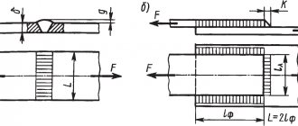
Welds along the section are differentiated:
- With the flank or longitudinal method, the force is directed parallel to the axis of the seam.
- In the frontal or transverse version, the forces make a right angle with the axis.
- The combined method combines the first two methods.
- In the oblique version, the force is applied at an angle to the axis of the seam.
Surface shape
The classification of welded joints includes a division based on the appearance of the surface shape of the welds. There are three types:
- Normal. The name speaks for itself.
- Convex. Otherwise - reinforced.
- Concave. In other words, weakened.
Each type has advantages depending on the working conditions. Convex seams are multi-layered. They are used when the joint being fastened is to be used under static loads.
However, it should be taken into account that increased influx will lead to additional consumption of electrodes, which increases the cost of the process. Concave ones are used when sheets of thin metal are to be fastened. Under dynamic loads, it is better to use flat or concave seams, since in this case there is no large difference between the base material and the seam.
Conditions in which a unit with welded surfaces will have to operate
The division depends solely on the operating conditions of the product unit. Workers include welds who must bear loads, sometimes significant ones. Non-working seams are simply connecting or connecting seams. Naturally, there is a significant difference in the requirements placed on them. Working seams must be inspected using suitable methods.
A weld that is not operational but is exposed to adverse weather conditions must be free of voids and cracks.
Width
According to this criterion, welding seams are of two types:
- widened;
- thread
When surfacing works, a widened version is used. If you have to weld sheets of thin metal, thread seams are chosen.
Number of layers
Layers are otherwise called passes. Classification on this basis has two options
- single-layer or single-pass;
- multi-layer or multi-pass.
A multilayer welding seam has its own peculiarity - it is a seam in which the number of layers coincides with the number of passes. If some layers were made in several passes, they will be called multi-pass. The scope of application of multilayer seams is butt welding. The multi-pass option is used for fillet welds and T-shaped welds.
With the multi-pass method, the next layer is applied to the previous one that has not cooled down. Before doing this, you need to quickly remove the welding slag. If welding is carried out on a section with a length of 200 mm, then it is carried out in different directions. When applying the next layer, annealing occurs in the previous one, which has a positive effect on the structure and mechanical characteristics of the weld.
Nature of execution
According to the nature of execution, welds are divided into one-sided and two-sided.
A single-sided seam is located on one side, and a double-sided seam is located on both sides.
According to execution technology
Depending on the technology used for fastening, there are four main types:
- The underwelding, where - the smaller part of the double-sided seam, is performed in advance to prevent burn-throughs during subsequent welding;
- a tack weld allows you to fix parts that are already positioned for welding;
- a temporary seam is necessary to hold the workpieces together for a while, and upon completion of the work it is removed.
- installation weld, used during installation of various structures.
In relation to the direction of current efforts
Butt welding contains another important classification, depending on the relationship to the direction of force:
- Longitudinal method of creating a joint (flank), in which the force acts parallel to the axis of the track;
- Transverse method (frontal) of the weld, in which its axis is perpendicular (90 degrees) to the axis of force;
- A combined welding connection includes both flank and transverse types;
- Oblique, in which the axis of the seam is located at an angle to the direction of the acting forces.
Welding of installation joints of building structures
GENERAL PROVISIONS
8.1.
When carrying out welding work, it is necessary to comply with the requirements of SNiP III-4-80, “Fire Safety Rules for Welding and Other Hot Work at National Economy Facilities”, approved by the GUPO Ministry of Internal Affairs of the USSR, “Sanitary Rules for Welding, Surfacing and Cutting of Metals”, approved by the Ministry of Health THE USSR. 8.2. Welding work must be supervised by a person who has a document on special education or training in the field of welding.
Welding work should be carried out in accordance with the approved welding production project (WPP) or other technological documentation.
8.3. Welding and tack welding must be performed by electric welders who have a certificate for the right to perform welding work, issued in accordance with the approved Rules for Certification of Welders.
Welders who have a certificate for the right to weld these steels are allowed to weld structures made of steels with a yield strength of more than 390 MPa (40 kgf/mm2).
8.4. If there is a corresponding requirement in the welding project or technological documentation for installation welding of butt joints of a given design, each welder must first weld test butt samples. Welding of samples should be carried out from the same type of rolled product (steel grade, thickness), in the same spatial position and using the same modes, materials and equipment as when making installation welded joints.
8.5. The dimensions of the plates for test samples of steel structures, as well as the shape and dimensions of samples for mechanical tests made from a welded test sample after external inspection and measurement of the butt weld, must comply with GOST 6996-66.
The dimensions of rod blanks for test samples of reinforcement of reinforced concrete structures must comply with the requirements of GOST 10922-75.
8.6. Mechanical tests of a butt welded joint of a test sample for steel structures must be carried out in accordance with GOST 6996-66, butt welded joints of reinforcement of reinforced concrete structures - GOST 10922-75 to the extent specified in table. 35.
If the results of mechanical tests are unsatisfactory, re-welding of test samples is permitted under the supervision of the welding supervisor.
Table 35
| Type of test | Number of samples, pcs. | Standardized indicator |
| Steel structures | ||
| 1. Static stretch | 2 | Tensile strength - not less than the lower limit of tensile strength of the base metal, regulated by the state standard |
| 2. Static bending | 2 | Static bending angle, degrees, for steel thickness, mm: |
| carbonaceous | ||
| up to 20 - no less than 100 | ||
| St. 20 - no less than 80 | ||
| low alloy | ||
| up to 20 - no less than 80 | ||
| St. 20 - no less than 60 | ||
| 3. Impact bending of weld metal | 3 | Impact strength - not less than the value specified in the technological documentation for field welding of this structure |
| Reinforcement of reinforced concrete structures | ||
| Tension to failure | 3 | Evaluation of results according to GOST 10922-75 |
8.7. If it is necessary to weld steel structures at an air temperature below minus 30 °C, welders must first weld test butt samples at a temperature not higher than the specified one. With satisfactory results of mechanical tests of test samples, the welder can be allowed to work at an air temperature 10 ° C below the welding temperature of test samples.
8.8. The welded surfaces of the structure and the welder’s workplace should be protected from rain, snow, and wind. At ambient temperatures below minus 10 °C, it is necessary to have an inventory room for heating near the welder’s workplace; at temperatures below minus 40 °C, a greenhouse must be equipped.
8.9. Fluctuations in the voltage of the electric current supply network to which the welding equipment is connected should not exceed ±5% of the nominal value. Equipment for automated and manual multi-station welding should be powered from a separate feeder.
8.10. Welding materials (coated electrodes, flux-cored wires, solid-section welding wires, fused fluxes) must comply with the requirements of GOST 9467-75, GOST 26271-84, GOST 9087-81.
8.11. When incoming inspection of welding materials, it is necessary to establish the availability of certificates or passports of the supplier company.
If there are no certificates for welding materials or their storage warranty period has expired, it is necessary to determine the mechanical properties of butt welded joints made using these materials. Welded butt samples should be tested for static tension, static and impact bending at a temperature of 20 °C in accordance with GOST 6996-66 and in the quantity specified in clause 8.6.
8.12. Welding materials (electrodes, wires, fluxes) must be stored in the warehouses of installation organizations in original packaging separately by brand, diameter and batch. The warehouse must be dry, with an air temperature of at least 15 °C.
8.13. Before use, coated electrodes, flux-cored wires and fluxes must be calcined according to the conditions specified in the technical specifications, data sheets, labels or tags of welding consumable manufacturers.
Solid welding wire should be cleaned of rust, grease and other contaminants.
Calcined welding materials should be stored in drying ovens at 45-100 ° C or in storage rooms with an air temperature of at least 15 ° C and a relative humidity of no more than 50%.
8.14. The welder must place a personal mark at a distance of 40-60 mm from the border of the weld seam he has made: by one welder - in one place, when performed by several welders - at the beginning and end of the seam. Instead of stamping, it is allowed to draw up as-built diagrams with the signatures of welders.
ASSEMBLY AND WELDING OF INSTALLATION CONNECTIONS OF STEEL STRUCTURES
8.15. Welding of structures during enlargement and in the design position should be carried out after checking the correctness of assembly.
8.16. The dimensions of the structural elements of the edges and seams of welded joints made during installation, and the maximum deviations of the cross-sectional dimensions of the seams of welded joints must correspond to those specified in GOST 5264-80, GOST 11534-75, GOST 8713-79, GOST 11533-75, GOST 14771-76* , GOST 15164-78, GOST 23518-79.
8.17. The edges of the elements to be welded at the locations of the seams and adjacent surfaces with a width of at least 20 mm for manual or mechanized arc welding and at least 50 mm for automated types of welding, as well as the junction of the initial and lead strips must be cleaned to remove rust, grease, paint , dirt, moisture, etc. In structures made of steel with a yield strength of more than 390 MPa (40 kgf/mm2), in addition, welding points and adjacent surfaces of devices should be cleaned.
8.18. Welding should be carried out under stable conditions. The maximum deviations of the specified values of the welding current and arc voltage during automated welding should not exceed ±5%.
8.19. The number of calcined welding materials at the welder’s workplace should not exceed half-shift requirements. Welding materials should be kept in conditions that prevent them from getting wet.
When welding structures made of steel with a yield strength of more than 390 MPa (40 kgf/mm2), electrodes taken directly from a calcining or drying furnace must be used within two hours.
8.20. Manual and mechanized arc welding of structures can be performed without heating at the ambient temperature given in Table. 36. At lower temperatures, welding should be carried out with preliminary local heating of the steel to 120-160 °C in a zone 100 mm wide on each side of the joint.
8.21. Places where mounting fixtures are welded to structural elements made of steel more than 25 mm thick with a yield strength of 440 MPa (45 kgf/mm2) or more must be preheated to 120-160 °C.
8.22. Automated submerged arc welding is allowed to be carried out without heating at the ambient temperature given in table. 37.
At temperatures below those indicated in the table. 37, automated submerged arc welding should be carried out with preliminary local heating to 120-160 °C.
8.23. Automated electroslag welding of elements, regardless of their thickness, in structures made of low-alloy or carbon steels can be performed without preheating at air temperatures down to minus 65 ° C.
8.24. In structures erected or operated in areas with a design temperature below minus 40 <°С and up to minus 65 °С inclusive. (during construction in climatic regions I1, I2, II2 and II3 according to GOST 16350-80), mechanized grinding, oxygen and air-arc surface cutting of sections of welds with defects, as well as welding of the restored section at the temperature indicated in the table. 36 should be performed after heating the welded joint zone to 120-160 °C.
Table 36
| Thickness of welded elements, mm | Minimum permissible ambient temperature, °C, when welding structures | ||||
| lattice | sheet volumetric and solid wall | lattice | sheet volumetric and solid wall | lattice and sheet | |
| of steel | |||||
| carbon | low-alloy with yield strength, MPa (kgf/mm2) | ||||
| £ 390 (40) | > 390 (40) | ||||
| Up to 16 | -30 | -30 | -20 | -20 | -15 |
| St. 16 to 25 | — | — | — | — | 0 |
| St. 16 to 30 | -30 | -20 | -10 | 0 | For a thickness of more than 25 mm, local preheating should be carried out regardless of the ambient temperature |
| St. 30 to 40 | -10 | -10 | 0 | 5 | |
| St. 40 | 0 | 0 | 5 | 10 | |
Table 37
| Thickness of the welded element, mm | Minimum permissible ambient temperature, °C, when welding steel structures | |
| carbon | low alloy | |
| Up to 30 | -30 | -20 |
| St. 30 | -20 | -10 |
8.25. Seams of connections of sheet volumetric and solid-wall structures with a thickness of more than 20 mm during manual arc welding should be performed in ways that reduce the cooling rate of the welded joint (sectional reverse-stage, sectional double layer, cascade, sectional cascade).
8.26. When performing double-sided manual or mechanized arc welding of butt, tee and corner joints with full penetration, it is necessary to remove its root from the reverse side to clean, defect-free metal before making the seam.
8.27. In the event of a forced break in work, mechanized arc or automated submerged arc welding can be resumed after clearing the crater and the adjacent end section of the weld 50-80 mm long from slag. This area and the crater must be completely covered with a seam.
8.28. Giving fillet welds a concave profile and a smooth transition to the base metal, as well as making butt welds without reinforcement (if this is provided for in the design drawings) should be ensured by selecting welding modes that correspond to the spatial locations of the structural elements being welded (when enlarged), or by mechanized cleaning with an abrasive tool.
8.29. The beginning and end of the seam of butt, corner and T-joints performed by automated types of welding should be brought outside the welded elements to the starting and leading strips. After welding is completed, the strips must be removed by oxyfuel cutting. The places where the strips were installed must be cleaned with an abrasive tool.
The use of starting and leading strips for manual and mechanized arc welding should be provided for in the KMD drawings.
It is not allowed to excite the arc and bring the crater onto the base metal beyond the weld.
8.30. Each subsequent bead (layer) of a multilayer welded joint must be performed after thoroughly cleaning the previous bead (layer) from slag and metal spatter. Sections of the seam with cracks should be removed before applying subsequent layers.
8.31. After finishing welding, the surfaces of the structure to be welded and the seams of welded joints must be cleaned of slag, splashes and deposits of molten metal.
Welded assembly and mounting fixtures must be removed without damaging the base metal or applying impact forces. The places where they are welded must be cleaned flush with the base metal, and unacceptable defects must be corrected.
The need to remove assembly bolts in assembly welded joints after completion of welding is determined by the installation organization.
8.32. The quality of tacks, welded joints, fastenings of assembly and installation devices, determined by external inspection, must not be lower than the quality of the main welded joints.
ASSEMBLY AND WELDING OF INSTALLATION CONNECTIONS OF REINFORCED CONCRETE STRUCTURES
8.33. The dimensions of structural elements of welded connections of reinforcement bars (rods with each other and with elements of embedded products) and the maximum deviations of the dimensions of the seams must correspond to those specified in GOST 14098-85.
Table 38
| Welding method | Characteristics of welding wire | Welding wire grades | Reinforcing steel class | ||
| A-I | A-II | A-III | |||
| Bathroom mechanized | Solid section | Sv-08A Sv-08AA | Recommended | Allowed | Not allowed |
| submerged in inventory form | Sv-08GA | Recommended | Allowed | ||
| or on a steel bracket | Sv-08G2S Sv-08GS Sv-10G2 Sv-10GA | Allowed | Recommended | ||
| Arc mechanized SODGP on a steel bracket-plate | Solid cross-section without additional protection | SV-20GSTUA (EP-245) St.-15GSTYUTSA (EP-439) | Recommended | Allowed | |
| Arc mechanized in inventory form or on a steel bracket-plate | Flux cored (self-shielding) wire | PP-AN3 PP-AN3S PP-AN11 SP-9 PPT-9 | Recommended | ||
| Arc mechanized with extended seams | PP-AN7 PP-AN19S | ||||
Note. When performing mechanized submerged arc welding of class A-I and A-II steel (grade 10GT) at temperatures below minus 40 °C, it is preferable to use Sv-08A, Sv-08AA or Sv-08GA wire.
8.34. To make installation connections of reinforcing steel of different classes, you should use the welding methods and welding materials indicated in Table. 38 and 39.
8.35. Bath or arc mechanized welding of reinforcement outlets, flat elements of embedded products among themselves, individual rods or rods with flat rolled elements should be carried out with specialized semi-automatic devices or modernized general-purpose semi-automatic machines.
8.36. For mechanized welding methods, universal DC welding current sources or with a rigid characteristic of up to 500 A should be used; for manual arc welding, universal DC welding current sources or with a decreasing characteristic and welding transformers for currents of up to 500 A should be used.
8.37. Before assembling structures, it is necessary to establish compliance with the design drawings of classes of rod reinforcement, steel grades of flat embedded products and connecting parts, and before welding, also the dimensions and accuracy of mating of connecting elements. The assembly accuracy of reinforcing bar outlets must comply with the requirements of GOST 10922-75 and GOST 14098-85.
8.38. Before welding (bathtub, multi-layer or extended seams), the reinforcing bars at the joint should be stripped to a length 10-15 mm longer than the weld or joint.
Table 39
| Reinforcement class | Recommended types of electrodes for welding | ||
| bathtub, bathtub-seam and arc multilayer seams of butt joints | extended seams of butt and overlap joints | arc manual tacks | |
| A-I | E42, E46, E42A, E46A | ||
| A-II | E50A, E55 | E42A, E46A, E50A | E50A, E55 |
| A-III; At-IIIC | E55, E60 | ||
| At-IVС | E50A, E55, E60 | ||
Note. In the absence of electrodes of types E55 and E60, bath-seam and arc multilayer welds of class A-III, At-IIIC and At-IVC steel can be performed with E50 A electrodes.
8.39. If the regulated gaps between the joining reinforcing bars are exceeded, it is allowed to use one intermediate insert with a length of at least 80 mm. Inserts should be made from reinforcement of the same class and diameter as the bars being joined. When butt welding rods with overlays, the excess of the gap must be compensated by a corresponding increase in the length of the overlays.
8.40. The length of the releases of reinforcing bars from the concrete of the structure must be at least 150 mm with gaps regulated by regulatory documents and at least 100 mm when using an insert.
8.41. Elements of prefabricated reinforced concrete structures should be assembled using devices and devices that fix their design position. Structures that have embedded support products must be additionally assembled using tacks using the same welding materials as the main seams. Tacks should be placed in places where welds will be subsequently applied.
8.42. When assembling structures, cutting the ends of rods or preparing their edges with an electric arc is not allowed.
8.43. After assembly for welding, the misalignment of the butted reinforcing bars, fractures of their axes, displacements and deviations in the dimensions of the elements of the welded joints must comply with the requirements of GOST 10922-75. Bending the rods to ensure their alignment can be carried out by heating to a temperature of 600-800 °C.
8.44. Welding of structural elements should be carried out in a securely fixed design position. It is prohibited to weld the releases of reinforcing bars of structures held by a crane.
8.45. After completion of welding, the welded joint must be cleaned of slag and metal splashes.
8.46. The welding work performed before concreting should be documented in acts of acceptance of a batch of reinforcement based on external inspection, and in the cases provided for by GOST 10922-75 - in acts of control by physical methods.
8.47. The designs of welded joints of rod reinforcement, their types and methods of implementation, depending on operating conditions, class and grade of steel being welded, diameter and spatial position during welding, must comply with the requirements of GOST 14098-85.
8.48. Tack welding by arc welding in cross-shaped joints of working reinforcement rods in accordance with GOST 14098-85 at subzero temperatures is prohibited.
8.49. Arc welding burns are not allowed on the surface of working reinforcement rods.
8.50. At the joints of reinforced concrete elements, the installed closed clamps (transverse rods) should be secured, as a rule, with binding wire. Arc welding at the intersection of clamp rods with longitudinal (working) reinforcement is allowed for some steel grades specified by GOST 14098-85.
8.51. To perform manual or mechanized welding at negative ambient temperatures down to minus 30 °C, you must:
- increase the welding current by 1% for every 3 °C drop in air temperature (from 0 °C);
- preheat reinforcement rods with a gas flame to 200-250 °C for a length of 90-150 mm from the joint; heating of the rods should be carried out after attaching inventory forms, steel brackets or round plates to them without disassembling the conductors used for temporary fastening of the mounted structures;
- reduce the cooling rate of rod joints made using bath welding methods by wrapping them with asbestos; if there are inventory molding elements, the latter should be removed after the completed welded joint has cooled to 100 °C and below.
- Manual and mechanized welding of flat elements, embedded parts and connecting products should be performed in accordance with the requirements of clause 8.20.
8.52. It is allowed to weld rod reinforcement at ambient temperatures down to minus 50 °C using a special technology developed in PPR and PPSR.
8.53. In connections of rods with overlays or overlaps and with elements of embedded products welded at subzero temperatures, removal of defects in the seams should be carried out after heating the adjacent area of the welded joint to 200-250 °C. Welding of the restored area should also be done after heating.
QUALITY CONTROL OF INSTALLATION WELDED JOINTS
8.54. Production quality control of welding work should include:
- incoming inspection of working technological documentation, assembled welded structures, welding materials, equipment, tools and fixtures;
- operational control of welding processes, technological operations and quality of welded joints;
- acceptance quality control of completed welded joints.
8.55. Incoming and operational control should be performed in accordance with SNiP 3.01.01-85.
Acceptance inspection of welded joints of steel structures
8.56. Quality control of welded joints of structures should be carried out using the methods indicated in Table. 40.
8.57. Cracks of all types and sizes in the seams of welded joints of structures are not allowed and must be eliminated with subsequent welding and inspection.
8.58. In appearance, the quality of welded joints of structures must satisfy the requirements of Table. 41.
8.59. Inspection of seams in welded joints of structures using non-destructive methods should be carried out after correction of unacceptable defects detected by external inspection.
Table 40
| Control methods | Type of structures, scope of control |
| 1. External inspection with checking the geometric dimensions and shape of the seams | All types of construction 100% |
| 2. Inspection of seams using non-destructive methods (radiographic, ultrasonic, etc.) in accordance with GOST 3242-79 | All types of structures in a volume of at least 0.5% of the length of the seams, as well as structures, methods and scope of control of which are provided for by additional rules or CM drawings |
| 3. Tightness and tightness tests | Structures (tank, etc.), the methods and scope of control of which are provided for by the additional rules of Section. 4 or KM drawings |
| 4. Mechanical tests of control samples | Structures for which the requirements for the mechanical properties of welded joints are provided for by CM drawings |
| 5. Metallographic examination of macrosections at the ends of welds of control samples or at the ends of butt welds of welded joints | Same |
Table 41
| Elements of welded joints, external defects | Quality requirements, acceptable defect sizes |
| Seam surface | Uniformly scaly, without burns, sagging, narrowing and breaks. Smooth transition to the base metal (should be specified in the KM and KMD drawings) |
| Undercuts | Depth - up to 5% of the thickness of the rolled product being welded, but not more than 1 mm |
| Elongated and spherical single defects | Depth - up to 10% of the thickness of the rolled product being welded, but not more than 3 mm Length - up to 20% of the length of the assessment section * |
| Elongated spherical defects in the form of a chain or cluster | Depth - up to 5% of the thickness of the rolled product being welded, but not more than 2 mm Length - up to 20% of the length of the assessment section The length of the chain or cluster is no more than twice the length of the assessment area |
| Defects (lack of penetration, chains and accumulations of pores) adjacent along the length of the seam | The distance between adjacent ends is at least 200 mm |
| Seams of welded joints of structures erected or operated in areas with a design temperature below minus 40 °C and up to minus 65 °C inclusive. | |
| Lack of penetration, lack of fusion, chains and accumulations of external defects | Not allowed |
| Undercuts: | |
| along the force | Depth - no more than 0.5 mm for welded rolled products with a thickness of up to 20 mm and no more than 1 mm for larger thicknesses |
| local across efforts | Length - no more than twice the length of the assessed section |
_____________
* Here and below, the length of the evaluation section should be taken according to the table. 43.
The areas with signs of defects and areas where seams intersect should be inspected primarily. The length of the control section must be at least 100 mm.
8.60. Based on the results of radiographic testing, the seams of welded joints in structures must meet the requirements of Table. 42, 43.
Table 42
| Elements of welded joints, internal defects | Quality requirements, acceptable defect sizes |
| Joints accessible for welding on both sides, joints on pads | |
| Lack of penetration at the root of the seam | Height - up to 5% of the thickness of the rolled product being welded, but not more than 2 mm Length - no more than twice the length of the assessed section |
| Joints without backing, weldable on one side | |
| Lack of penetration at the root of the seam | Height - up to 15% of the thickness of the rolled product being welded, but not more than 3 mm |
| Elongated and spherical defects: | |
| single | Height - no more than h* values |
| forming a chain or cluster | Height - no more than 0.5h* Length - no more than the length of the assessment section |
| extended | Length - no more than a ratio * |
| lack of penetration, chains and clusters of pores adjacent along the length of the seam | The distance between adjacent ends is at least 200 mm |
| total in the longitudinal section of the seam | The total area on the assessed site is no more than S* |
| Seams of welded joints of structures erected or operated in areas with a design temperature below minus 40 °C to minus 65 °C inclusive, as well as structures designed for endurance | |
| Lack of penetration, lack of fusion, elongated defects, chains and clusters of defects | Not allowed |
| Single spherical defects | Height - no more than 0.5h* The distance between adjacent defects is not less than twice the length of the assessment section |
_____________
* The values of h and S should be taken according to the table. 43.
Table 43
| Minimum thickness of a structural element in a welded joint, mm | Length of the evaluation section, mm | Acceptable sizes of single defects | |
| h, mm | S, mm2 | ||
| From 4 to 6 | 15 | 0,8 | 3 |
| St. 6 to 8 | 20 | 1,2 | 6 |
| St. 8 to 10 | 20 | 1,6 | 8 |
| St. 10 to 12 | 25 | 2,0 | 10 |
| St. 12 to 14 | 25 | 2,4 | 12 |
| St. 14 to 16 | 25 | 2,8 | 14 |
| St. 16 to 18 | 25 | 3,2 | 16 |
| St. 18 to 20 | 25 | 3,6 | 18 |
| St. 20 to 60 | 30 | 4,0 | 18 |
Designations adopted in table. 43: h - permissible height of a spherical or elongated single defect; S is the total area of defects in the longitudinal section of the weld in the evaluation area.
Note. The sensitivity of the control is set according to the third class according to GOST 7512-82.
When assessing the height of defects h, the following dimensions of their images on radiograms should be taken:
for spherical pores and inclusions - diameter;
" elongated " " - width.
8.61. Based on the results of ultrasonic testing, the seams of welded joints in structures must meet the requirements of Table. 44.
Table 44
| Welded joints | Minimum thickness of a structural element in a welded joint, mm | Length of the evaluation section, mm | Fixed equivalent area of a single defect, mm2 | Permissible number of single defects in the evaluation area, pcs. | |
| smallest search engine | acceptable estimate | ||||
| Butt, corner T, lap | St. 6 to 10 | 20 | 5 | 7 | 1 |
| St. 10 to 20 | 25 | 5 | 7 | 2 | |
| St. 20 to 30 | 30 | 5 | 7 | 3 | |
| St. 30 to 60 | 30 | 7 | 10 | 3 | |
8.62. In the seams of welded joints of structures being built or operated in areas with a design temperature below minus 40 °C to minus 65 °C inclusive, as well as structures designed for endurance, internal defects are allowed, the equivalent area of which does not exceed half the values of the permissible estimated area ( see table 44). In this case, the smallest search area must be reduced by half. The distance between defects must be at least twice the length of the assessment section.
8.63. In joints that can be welded on both sides, as well as in joints on backings, the total area of defects (external, internal, or both) in the evaluation area should not exceed 5% of the longitudinal sectional area of the weld in this area.
In joints without backing, accessible for welding only on one side, the total area of all defects in the evaluation area should not exceed 10% of the longitudinal sectional area of the weld in this area.
8.64. If an unacceptable defect is detected, its actual length should be identified, the defect corrected and checked again.
If a defect is re-identified, the entire welded joint is subject to inspection.
8.65. Control of the tightness of seams in welded joints should, as a rule, be carried out using bubble or capillary methods in accordance with GOST 3242-79 (tightness should be understood as the ability of a joint not to allow water or other liquids to pass through).
The vacuum value with the bubble method must be at least 2500 Pa (250 mm water column).
The duration of control by the capillary method should be at least 4 hours at positive and less than 8 hours at negative ambient temperatures.
8.66. The tightness control (tightness should be understood as the ability of a connection not to allow gaseous substances to pass through) of the seams of welded joints should, as a rule, be carried out using the bubble method in accordance with GOST 3242-79.
8.67. Welded joints controlled at negative ambient temperatures should be dried by heating until the frozen water is completely removed.
8.68. Mechanical tests of control samples are carried out if there are requirements in the CM drawings for the strength, ductility and toughness of the weld metal and the heat-affected zone of the welded joint.
The requirements for control samples and their welding are similar to those for test samples (see 8.7).
The number of control samples during mechanical tests must be at least:
- for static tension of the butt joint - 2;
- for static tension of the weld metal of butt, corner and T joints - 3 each;
- for static bending of the butt joint - 2;
- for impact bending of weld metal and heat-affected zone of butt joint - 3; the type of sample and the location of the cuts must be indicated in the CM drawings;
- on the hardness (HB) of the weld metal and the heat-affected zone of the welded joint of low-alloy steel (at least four points) - 1.
8.69. Metallographic studies of macrosections of welded joints should be carried out in accordance with GOST 10243-75*.
8.70. Inadmissible defects discovered as a result of control tests must be eliminated, and areas of the seam with unacceptable defects must be welded again and inspected.
Defective areas of welds should, as a rule, be removed in one of the following ways:
mechanized stripping (with an abrasive tool) or mechanized cutting.
It is allowed to remove defects in welded joints by manual oxygen cutting or air-arc surface cutting with mandatory subsequent cleaning of the cut surface with an abrasive tool to a depth of 1-2 mm with the removal of protrusions and sagging.
8.71. All burns to the surface of the base metal by the welding arc should be cleaned with an abrasive tool to a depth of 0.5-0.7 mm.
8.72. When removing defects in welded joints, weld roots and tacks by mechanized cleaning (with an abrasive tool), the marks on the metal surface must be directed along the welded joint:
- when cleaning the installation sites of the initial and lead strips - along the end edges of the structural elements being welded;
- when removing seam reinforcement - at an angle of 40-50° to the seam axis.
The weakening of the section when processing welded joints (recess into the base metal) should not exceed 3% of the thickness of the element being welded, but not more than 1 mm.
8.73. When removing surface defects from the end of a weld with an abrasive tool without subsequent welding, it is allowed to go deeper with a slope of no more than 0.05 on the free edge into the thickness of the metal by 0.02 of the width of the mating element, but no more than 8 mm on each side. In this case, the total weakening of the section (taking into account the permissible weakening along the thickness) should not exceed 5%. After processing the ends of the seams, it is necessary to dull the sharp edges.
8.74. Correction of welded joints by caulking is not allowed.
8.75. Residual deformations of structures that arise after installation welding must be eliminated by thermal or thermomechanical action in accordance with the requirements of clause 4.2.
8.76. Methods and scope of non-destructive testing of elements of mounted structures are given in the additional rules of Section. 4.
Acceptance inspection of welded joints of reinforced concrete structures
8.77. Acceptance inspection of completed welded butt joints of reinforcement must include external inspection and a set of tests carried out in accordance with GOST 10922-75 and GOST 23858-79.
The volume of a batch of welded joints of fittings outlets is established by the same standards. Concreting the structure before receiving the results of assessing the quality of welded joints is not permitted.
8.78. Welding of defects allowed for correction should be done with electrodes with a diameter of 4 mm after cleaning the defect site with an abrasive tool and preheating the joint to 200-250 °C.
8.79. Welded butt joints of reinforcement that do not meet the requirements of GOST 10922-75 or GOST 23858-79 must be cut out. In place of the cut joint, an intermediate insert with a length of at least 80 mm should be welded, followed by ultrasonic inspection of the two welded joints made.
According to the shape of the outer surface
According to the shape of the clutch surface, they are divided into three main types:
- Convex (reinforced) are multi-layer seams used in clutches under static loads, but increased influx leads to excessive consumption of electrode metal and therefore an economic justification is required for its use.
- Concave (loose) methods are used to hold thin metal together.
- Normal or flat are relevant for dynamic loads, since they do not have a special difference between the track and the base metal.
By type of welding
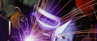
The classification of welds by type of welding is divided depending on the type of impact of the welding machine. For example, when working in an environment of argon or other protective gas, the connection will be nothing other than “gas”; when working with an electrode, it will be “electric arc”. The most basic types are the following seams:
- manual arc welding - butt or lap joints are made manually using an electrode. Thus, it is possible to fasten almost any metal with a thickness from 0.1 to 100 mm in any position;
- automatic welding, which is carried out when working with a device - a transformer, rectifier or inverter;
- welding in inert gas. Such butt, corner and lap joints are considered the most durable, since welding occurs in an environment of inert gases, which protect it from oxidation. The big advantage of such fastening is the aesthetic appearance and the absence of waste and slag;
- gas welding - the track is formed under the influence of temperature, which is created due to the combustion of the working gas emanating from the torch;
- solder connections that are made using a soldering iron.
In addition to those described, there are many more methods for connecting parts, both conventional and non-standard, which are used for welding parts in hard-to-reach places. For example, seams can be single-layer (a) or multi-layer (b, c), in which several rollers are applied, located at the same level of the cross-section of the seam.
Permanent connections
Permanent connections include: riveted, welded, obtained by soldering, gluing, by pressing parts with tension.
Riveted connections
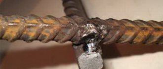
Riveted joints are used in connecting parts made of metals, which are generally difficult to weld, when connecting metal products with non-metal products (Figure 18.1). These connections are used in structures operating under the influence of shock and vibration loads.
A rivet is a round rod with a head at one end; the shape of the head varies.
Solder connection
When connecting by soldering, in contrast to welding, the soldering point is heated only to the melting temperature of the solder, which is much lower than the melting temperature of the material of the parts being connected. The connection of parts is achieved by filling the gap between them with molten solder. Soldering seams are conventionally depicted according to GOST 2.313-82 with a line twice as thick as the solid main line and are indicated by a symbol that is applied on a leader line from the solid main line.
A seam made along a closed line (along the perimeter) is indicated by a leader line ending in a circle with a diameter of 3...5 mm (Figure 18.2).
Bonding by gluing
The seam obtained during gluing is depicted in the same way as the seam during soldering, only a different icon is placed in the designation (Figure 18.3).