Water delivery channels are among the most common utility facilities. Pipelines not only provide consumers’ domestic needs for cold and hot water, but also act as sources of liquid in industrial infrastructure. Moreover, there are no less significant communications through which oil and gas products are transported from the production site to processing plants. And in each case, the basis of such channels is the main pipeline. These are transmission lines of the target liquid or gaseous resource, connecting the source of production or content with the consumer.
Pipeline composition
The basis of the infrastructure is formed directly by metal pipes, but without plumbing shut-off valves their operation is impossible. Almost all water, gas and oil transportation lines have loopings and branches in different configurations, the design of which includes the inclusion of fittings, regulators and taps. At connection points to pumping stations, control and measuring instruments such as flow sensors and pressure gauges are usually installed. Accordingly, with their help, pressure indicators in the circuit and the volume of pumped resource are monitored. Cleaning agents are also common additions to main pipelines. The operation of canals supplying consumers with drinking water, for example, is accompanied by fine cleaning. For this purpose, filters with ionization and aeration effects are used. Industrial gas and oil refining networks also use condensate collectors and methanol injection units.
Types of transported substances
Trunk structures transport a huge amount of substances in different states of aggregation.
The main ones:
- natural gases, as well as petroleum hydrocarbons;
- hydrocarbon gaseous compounds that were obtained artificially;
- liquefied hydrocarbon gases;
- oil that is transported through pipelines from main pumping stations to processing sites;
- petroleum products that are obtained by refining crude oil.
Helpful information! The extracted oil is delivered to oil gathering points through special pipelines. Then it goes through oil collection pipes to the main buildings of the processing plant.
Main characteristics of pipes
Modern plastic pipeline structures are not used in main lines due to their low service life. As a rule, stainless steel sections are used, connected by electric welding or a spiral seam. SNiP section 2.05.06-85 notes that for channels up to 500 mm thick, pipes made of carbon steel should be used. As the diameter increases to 1020 mm, low-alloy mild alloys begin to be used. If we are talking about a thickness of more than 1400 mm, then the installation is made from elements whose metal is in a thermomechanically strengthened state. As the same SNiP indicates, main pipelines when connecting must also be maintained in terms of curvature. At each meter segment, the standard deviation does not exceed 1.5 mm. The total curvature should be within 0.2% of the entire channel length.
Purpose of the main gas pipeline
The production of natural gas is directly related to its delivery through pipelines from the field and processing plants to the end consumer. All main lines and pipelines laid between fields belong to the Unified Gas Supply System of the Russian Federation.
Here it is necessary to clarify that mains are large pipelines that deliver gas to an enterprise or distribution station. Lines laid to a specific consumer are called branches.
The main pipes are distinguished by their large diameter - 720-1420 mm and the maintenance of excess pressure inside. The construction of main gas pipelines is carried out using seamless cold-rolled pipes.
The laying of highways is carried out using:
- underground installation, which is considered the most profitable. In this case, for laying pipes, trenches with a depth of 0.8 m are used if the diameter of the pipes is up to a meter, and 1 m if the diameter is up to 1.4 m. In places with swampy or peaty soil, trenches are dug to a depth of 1.1 m, for rocks norm 0.6 m.
- above-ground, when pipes are laid on supports above the ground.
- ground, in this case bulk dams are installed.
- underwater, when gas production is carried out under a body of water, installation of an underwater gas pipeline is necessary.
Responsibility for the functional condition of highways lies with state-owned companies.
Classification of backbone networks
Pipelines are divided according to the type of serviced resource, installation method and performance indicators. As for the first classification, the possibilities of using communications for transporting both liquid media (oil, water, oil, etc.) and gas mixtures have already been noted. In this case, for the second group, a division into classes according to pressure level is used: ranges 2.5-10 MPa and 1.2-2.5 MPa. At oil refineries, they use a classification based on the diameter of the main pipeline - this is a spectrum from 300 to 1200 mm, in which dividing boundaries can be distinguished at points of 500 and 1000 mm. With regard to the method of laying communications, above-ground and underground methods are usually considered. Accordingly, in one case, open installation with direct access to channel maintenance is assumed, and in the second, sealed pipe laying with complete backfilling and expectation of long-term operation.
Installation
The design and laying of routes (distance to populated areas, line depth, etc.) are regulated by standards.
For each type of pipeline, pipe rolling and the method of its installation are selected, taking into account operational loads and the purpose of the line.
When assembling steel mains, a single method is used or a technical corridor is used (i.e., parallel pipes are placed).
Let us briefly consider the process of installing an underground main gas pipeline. It consists of several stages:
- delivery and unloading of pipes (rented pipes are delivered in special long vehicles);
- laying parts in prepared trenches/ditches;
- trench welding;
- tests;
- insulation of joints (performed only after a hydraulic test of the communication).
Features of offshore pipeline channels
This is also one of the methods for laying trunk networks for transporting gas and liquid resources, but it is used less frequently. The offshore pipeline is placed underwater after a comprehensive analysis of local water conditions. In particular, the preparation of the project is preceded by the determination of the speed of the bottom current, engineering-geological parameters, coastal topography and the ambient temperature in which the main pipeline will be located. The rules also define special requirements for ensuring protection. The external walls of the pipes must have thermal insulation, a concrete coating and cathodic anti-corrosion protection. Low-alloy and low-carbon steel structures are used as the main material for underwater channels. As a rule, electric-welded straight-seam or hot-rolled seamless pipes.
Environmental Safety
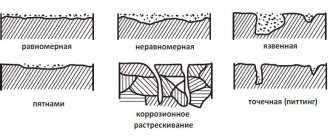
Trunk pipelines often transport hazardous and corrosive substances, so when installing them, care must be taken to protect the environment from the negative impact that may result from a leak.
Of course, the main protection is high-quality installation of the structure, which can include the use of high-quality materials, competent design of main pipelines and compliance of their characteristics with standards. The main must be covered in a layer of insulation that protects it from corrosion and exposure to external factors - given the danger of leaks, the likelihood of their occurrence must be reduced to the limit.
If the area through which the pipeline runs is susceptible to erosion, the soil must be stabilized. For the normal functioning of a structure in harsh climatic conditions or during seismic activity, it must be equipped with reinforced insulation and compensators.
Conclusion
This article provided a detailed answer to the question of what main pipelines are. These structures are an important element of the infrastructure of any country, so their design and creation are given serious attention. There are many types of backbone networks, each of which is subject to individual, but always strict requirements, which is due to the considerable risk of a local catastrophe as a result of a violation of the integrity of the structure.
Design of main canals
At the project creation stage, a set of technical documents is developed that describes design parameters, diagrams, drawings and a general plan for the construction of pipeline transport. A study of the area for laying a canal is also being carried out. Geodetic, geological and environmental conditions are assessed, as well as economic data justifying the project. The basis of the documentation is formed by information about the characteristics of the main pipeline - this can be information on throughput, pressure, number of transition stations and branches. Engineers also take into account the operational perspective of the infrastructure. The possibility of future modernization, reorientation or expansion of the network in accordance with new conditions of its use will depend on it.
What are they needed for?
Transportation of petroleum products by water and rail over long distances is associated with certain risks and high costs. Trunk pipelines simplify the transportation of raw materials from the regions where they are mined to places of final consumption. Pipeline transport:
- provide pumping range, almost uninterrupted operation during the entire operation;
- works in different climatic conditions - can be laid through any regions.
The construction of pipelines is subject to mechanization of construction and installation work from year to year. This simplifies the construction process and reduces the cost of transporting raw materials.
Laying main pipes
The construction of the pipeline is carried out in accordance with the technical solutions adopted in the project, taking into account the specific installation conditions. As a rule, laying is carried out using earth embankments or supports acting as a load-bearing base or foundation. Moreover, in one technological corridor of the network, pipes for different purposes can be laid simultaneously - this is how combined or adjacent routes are formed. The minimum depth level for the construction of main pipelines is 80 cm for diameters less than 1000 mm and 100 cm for channels with a thickness of more than 1000 mm. The depth of occurrence increases on unstable soils if the support base is laid on irrigated or arable lands.
Use of pipe types depending on installation method
In the case of underground installation, the resistance to soil corrosion and corrosion caused by stray currents is taken into account. The ring stiffness of pipes is important at high ground loads, for example in cities. Resistance to dynamic loads from the operation of vehicles and machinery - indicators that are relevant for laying highways in industrial areas.
In mining conditions, in seismically hazardous areas, in areas with possible ground subsidence, pipes are additionally protected with special equipment - compensators that increase deformation capacity. Such engineering solutions significantly affect the final cost of main pipelines. This is one of the main reasons for the increased use of polymer pipes. Their own ability to work deformation can significantly reduce the use of expansion joints.
When pipelines are installed openly, in addition to atmospheric corrosion, the service life is affected by exposure to ultraviolet radiation. The latter is especially true for some types of plastic pipes.
Pipeline protection means
The basic requirements for insulation are determined by the need to prevent corrosion processes. The protective shell must provide dielectric properties, and also be continuous, waterproof and durable. These requirements can be met by special paint and varnish compositions, polyvinyl chloride and polyethylene coatings, bitumen and silicon mastics. Depending on the characteristics of the seismic zone, a special construction of embankments may be required that will prevent the impact of ground movements on the main pipeline - SP number 14.13330 of 2011, in particular, indicates the need to relieve stress through loose sand embankments, sandy loams and loams. During operation, such a base will act as a damper cushion, minimizing vibrations and vibrations.
Regulatory regulation of requirements for water and gas pipes
The main document GOST 3262-75 “Steel water and gas pipes” defines
- Requirements for the assortment - dimensions and weight, length, connection methods, maximum deviations in production accuracy are regulated.
- Technical conditions - features (for example, chamfers), the presence of couplings, etc., production quality and permissible defects, end cutting angles, strength requirements, etc.
- Test methods - selection of samples for testing, inspection, hydraulic tests, bending tests, flattening tests, expansion tests, weld control, protective coating thickness, etc.
- Labeling and transportation conditions.
The requirements for precision production and technical capabilities of pipes for main pipelines are constantly growing. Despite the fact that steel pipes currently occupy the majority of the market, this share is steadily declining. This is due to the emergence of new technologies, and with them new requirements for operational characteristics.
Network Maintenance
Already in the design documentation there should be a schedule for the implementation of preventive measures aimed at maintaining the optimal technical condition of the pipeline. The maintenance team checks the tightness of the circuit, the condition of the connecting nodes, measuring equipment and transition stations. Also, at the stage of putting the infrastructure into operation, a protection zone for main pipelines is established, in which excavation works, the laying of other transport networks, construction activities, etc. are prohibited. The range of this territory around the canal is on average 25-100 m.
Main structures included in the gas pipeline complex
In accordance with the joint venture, the construction of main gas pipelines and branches is carried out using pipes with a diameter of up to 1420 mm. The gas pipeline complex includes:
- gas well with a “loop”;
- gas collection point;
- gas field reservoir;
- a complex of treatment facilities;
- gas compressor station;
- main gas pipeline line;
- locking devices;
- transition compressor station;
- transitions;
- communication line;
- spare set of pipes;
- a road laid along the highway with access roads;
- gas distribution installations;
- bends;
- system of protective structures;
- looping;
- city gas pipeline system.
Looping is a line of pipes that duplicates the main pipeline and is laid parallel to it. This branch is installed to increase the productivity of the main highway. The location of the looping is not regulated.
SNiP 2.05.06-85*. Main pipelines.
BUILDING REGULATIONSMAIN PIPELINES
SNiP 2.05.06-85*
DEVELOPED BY VNIIST Ministry of Oil and Gas Construction (Candidate of Technical Sciences I. D. Krasulin -
topic leader, candidates technical.
Sciences V.V. Rozhdestvensky, A.B. Ainbinder,
Eng
.
L.A. Solovyova, Ph.D.
Sciences V. F. Khramikhina, A. S. Bolotov, N. P. Glazov, S. I. Levin, V. V. Spiridonov, A. S. Gekhman, V. V. Pritula, V. D. Tarlinsky, A D. Yablokov) with
the participation of YuzhNIIGiprogaz
(I. I. Pankov
and
N. N. Zheludkov},
State Gas Supervision of the USSR
R. G. Toropov).
VNIIGaz of Mingazprom (candidates of technical sciences
S.V. Karpov
and Z.
I. Nefedova),
Hydraulic Pipeline of the Ministry of Oil Industry
(B.A. Alimov)
and the Ministry of Economy and State Enterprise named after I.M. Gubkin of the Ministry of Higher Education of the USSR (Doctor of Technical Sciences, Prof. L.
G. Telegin).
INTRODUCED by the Ministry of Oil and Gas Construction.
PREPARED FOR APPROVAL BY Glavtekhnormirovanie Gosstroy USSR (I.V. Sessin).
PREPARED FOR REPUBLICATION by the Technical Standardization Department of the Gosstroy of Russia (N.A. Shishov).
SNiP 2.05.06-85* is a reissue of SNiP 2.05.06-85 with amendments No. 1, No. 2, approved by resolutions of the USSR State Construction Committee dated January 8, 1987 No. 1, dated July 13, 1990 No. 61, and amendment No. 3, approved by Resolution of the Ministry of Construction of Russia dated November 10, 1996 No. 18-78.
Items and tables to which changes have been made are marked in these building codes and regulations with an asterisk.
When using a regulatory document, you should take into account the approved changes to building codes and regulations and state standards published in the journal “Bulletin of Construction Equipment” and the information index “State Standards”.
Gosstroy USSR
| Building regulations | SNiP 2.05.06-85* |
| Main pipelines | In return SNiP II-45-75 |
These standards apply to the design of new and reconstructed main pipelines and branches from them with a nominal diameter of up to 1400 mm inclusive. with excess pressure of the environment over 1.2 MPa (12 kgf/cm2) up to 10 MPa (100 kgf/cm2) (for single installation and installation in technical corridors) for transportation:
a) oil, petroleum products (including stable condensate and stable gasoline), natural, petroleum and artificial hydrocarbon gases from areas of their production (from fields), production or storage to places of consumption (oil depots, transshipment bases, loading points, gas distribution stations, individual industrial and agricultural enterprises and ports);
b) liquefied hydrocarbon gases of fractions C3 and C4 and their mixtures, unstable gasoline and petroleum gas condensate and other liquefied hydrocarbons with a saturated vapor pressure at a temperature of plus 40 ° C not exceeding 1.6 MPa (16 kgf/cm2) from the areas of their production ( fields) or production (from the main pumping stations) to the point of consumption;
c) commercial products within compressor stations (CS) and oil pumping stations (OPS), underground gas storage stations (UGS), booster compressor stations (BCS), gas distribution stations (GDS) and gas flow metering units (UZRG);
d) pulse, fuel and starting gas for CS, UGS, BCS, GDS, UZRG and gas reduction points (GRP).
The main pipelines include:
pipeline (from the point of exit from the field of commercial products prepared for long-distance transport) with branches and loopings, shut-off valves, transitions through natural and artificial obstacles, connection points for oil pumping station, compressor station, UZRG, PRG, nodes for starting and receiving treatment devices, condensate collectors and devices for methanol input;
installations of electrochemical protection of pipelines from corrosion, lines and structures of technological communication, means of telemechanics of pipelines;
power lines intended for servicing pipelines and power supply devices and remote control of shut-off valves and installations for electrochemical protection of pipelines;
fire-fighting means, anti-erosion and pipeline protection structures;
tanks for storing and degassing condensate, earthen pits for emergency release of oil, petroleum products, condensate and liquefied hydrocarbons;
buildings and structures of the linear pipeline operation service;
permanent roads and helipads located along the pipeline route, and approaches to them, identification and signal signs for the location of pipelines;
head and intermediate pumping and loading pumping stations, tank farms, compressor stations and gas distribution stations;
SPHG;
heating points for oil and petroleum products; pointers and warning signs.
These standards do not apply to the design of pipelines laid in cities and other populated areas, in offshore areas and fields, as well as pipelines intended for transporting gas, oil, petroleum products and liquefied hydrocarbon gases that have a corrosive effect on the metal of pipes or cooled to a temperature below minus 40 °C.
The design of pipelines intended for transporting stable condensate and stable gasoline should be carried out in accordance with the requirements of these standards for oil pipelines.
Stable condensate and gasoline include hydrocarbons and their mixtures that have a saturated vapor pressure of less than 0.2 MPa (2 kgf/cm2) (abs) at a temperature of plus 20 °C.
| Introduced by the Ministry of Oil and Gas Construction | Approved by resolution State Construction Committee of the USSR dated March 18, 1985 No. 30 | Effective date: January 1, 1986. |
The design of pipelines for liquefied hydrocarbons with a saturated vapor elasticity at a temperature of plus 20 °C above 0.2 MPa (2 kgf/cm2) - liquefied hydrocarbon gases, unstable gasoline and unstable condensate and other liquefied hydrocarbons - should be carried out in accordance with the requirements set out in Section . 12.
Design of buildings and structures, including utilities, located at CS sites. NPS, GRS. SPHG and DCS. should be carried out in accordance with the requirements of regulatory documents for the design of relevant buildings and structures approved by the USSR State Construction Committee, taking into account the requirements of these standards.
The design of gas pipelines with a pressure of 1.2 MPa (12 kgf/cm2) or less, oil pipelines and oil product pipelines with a pressure of up to 2.5 MPa (25 kgf/cm2), intended for laying in the territory of populated areas or individual enterprises, should be carried out in accordance with the requirements of SNiP 2.04.08-87*, SNiP 2.11.03-93 and SNiP 2.05.13-90.
1. GENERAL PROVISIONS
1.1.
Main pipelines (gas pipelines, oil pipelines and oil product pipelines)1 should be laid underground (underground installation).
The laying of pipelines on the surface of the earth in an embankment (ground laying) or on supports (above-ground laying) is allowed only as an exception with appropriate justification in the cases given in clause 7.1. In this case, special measures must be taken to ensure reliable and safe operation of pipelines.
__________
1 In the text of the standards, with the exception of specially stated cases, instead of the words: “main pipeline(s)” the word “pipeline(s)” will be used.
1.2.
The laying of pipelines can be carried out singly or in parallel with other existing or projected main pipelines - in a technical corridor.
1.3.
The technical corridor of main pipelines should be understood as a system of parallel pipelines along one route intended for transporting oil (petroleum products, including liquefied hydrocarbon gases) or gas (gas condensate).
In some cases, subject to a feasibility study and ensuring the reliability of pipeline operation, joint laying of oil pipelines (oil product pipelines) and gas pipelines in one technical corridor is allowed.
1.4.
The maximum permissible (total) volumes of transportation of products within one technical corridor and the distances between these corridors are determined in accordance with building codes and regulations approved in the prescribed manner.
1.5.
It is not permitted to lay main pipelines through the territories of populated areas, industrial and agricultural enterprises, airfields, railway stations, sea and river ports, marinas and other similar objects.
1.6.
To ensure normal operating conditions and eliminate the possibility of damage to main pipelines and their facilities, security zones are established around them, the size of which and the procedure for carrying out agricultural and other work in these zones are regulated by the Rules for the Protection of Main Pipelines.
1.7.
The temperature of gas, oil (petroleum products) entering the pipeline must be set based on the possibility of transporting the product and the requirements for the safety of insulating coatings, strength, stability and reliability of the pipeline.
The need and degree of cooling of the transported product is decided during the design.
1.8.
Pipelines and their structures should be designed taking into account the maximum industrialization of construction and installation work through the use, as a rule, of pipes with factory insulation and prefabricated structures in a block-complete design from standard and standard elements and parts manufactured in factories or in stationary conditions, ensuring their high-quality production. At the same time, the decisions made in the project must ensure uninterrupted and safe operation of pipelines.
2. CLASSIFICATION AND CATEGORIES OF MAIN
PIPELINES
2.1.
Main gas pipelines, depending on the operating pressure in the pipeline, are divided into two classes:
I - at operating pressure over 2.5 to 10.0 MPa (over 25 to 100 kgf/cm2) inclusive;
II - at operating pressure above 1,
2 to 2.5 MPa (over 12 to 25 kgf/cm2) incl.
2.2.
Main oil pipelines and oil product pipelines, depending on the diameter of the pipeline, are divided into four classes, mm:
I - with a nominal diameter of over 1000 to 1200 inclusive;
II - the same, over 500 to 1000 inclusive;
III - the same. over 300 to 500 inclusive;
IV - 300 or less.
2.3.
Main pipelines and their sections are divided into categories, the requirements for which, depending on operating conditions, the scope of non-destructive testing of welded joints and the value of test pressure, are given in Table. 1.
Table 1
| Category of the pipeline and its section | Coefficient of pipeline operating conditions when calculating its strength, stability and deformability m | Number of assembly welded joints subject to physical control, % of the total number | Test pressure and duration of pipeline testing |
| IN | 0,60 | Accepted | |
| I | 0,75 | By | |
| II | 0,75 | SNiP III-42-80* | |
| III | 0,90 | ||
| IV | 0.90 | ||
| Note. When testing a pipeline for its linear part, it is allowed to increase the pressure to a value that causes stress in the pipe metal to the yield point, taking into account the minus tolerance for wall thickness. | |||
2.4.
Categories of main pipelines should be taken according to table. 2.
table 2
| Purpose of the pipeline | Pipeline category when laid | |
| underground | ground and above ground | |
| For transportation of natural gas: | ||
| a) with a diameter of less than 1200 mm | IV | III |
| b) with a diameter of 1200 mm or more | III | III |
| c) in the northern construction-climatic zone | III | III |
| For transportation of oil and petroleum products: | ||
| a) with a diameter of less than 700 mm | IV | III |
| b) with a diameter of 700 mm or more | III | III |
| c) in the northern construction-climatic zone | III | III |
2.5.
Categories of sections of main pipelines should be taken according to table. 3*.
Table 3*
| Category of sections when laying | |||||||
| Purpose of pipeline sections | gas pipelines | oil pipelines and oil product pipelines | |||||
| underground | ground | aboveground | underground | ground | aboveground | ||
| 1 | 2 | 3 | 4 | 5 | 6 | 7 | |
| 1. Crossing water barriers: a) navigable - in the riverbed and coastal sections with a length of at least 25 m each (from the average low water horizon) with the diameter of the pipeline. mm: | |||||||
| 1000 or more | I | — | I | IN | — | IN | |
| less than 1000 | I | — | I | I | — | I | |
| b) non-navigable water mirrors with a width of 25 m or more during low-water periods - in the channel part and coastal sections with a length of at least 25 m each (from the average low-water horizon) with a pipeline diameter, mm: | |||||||
| 1000 or more | I | — | I | IN | — | I | |
| less than 1000 | I | — | I | I | — | I | |
| c) non-navigable water mirrors with a width of up to 25 m during low-water periods—in the channel part, irrigation and diversion canals | I | — | II | I | I | ||
| d) mountain streams (rivers) | I | — | II | I | — | I | |
| e) river floodplains along the high water horizon of 10% probability with pipeline diameter, mm: | |||||||
| 700 or more | I | — | II | I | — | I | |
| less than 700 | II | — | II | I | — | I | |
| f) sections with a length of 1000 m from the boundaries of the high water horizon 10% security | — | — | — | I | — | II | |
| 2. Crossings through swamps like: a) I | III | III | III | II, III1 | II, III1 | II, III1 | |
| b) II | II | III | III | II | II | III | |
| c) III | I | II | II | IN | IN | I | |
| 3. Crossings through railways and highways (on stretches): | |||||||
| a) railways of the general network, including sections 40 m long each on both sides of the road from the axes of the outer tracks, but not less than 25 m from the base of the embankment of the roadbed | I | — | I | I | — | I | |
| b) access railways of industrial enterprises, including sections 25 m long each on both sides of the road from the axes of the outer tracks | I | — | II | III | — | II | |
| c) highways of categories I and II, including sections 25 m long each on both sides of the road from the base of the embankment or the edge of the roadbed excavation | I | — | I | I | — | I | |
| d) highways of II, III-p, IV, IV-p categories, including sections 25 m long each on both sides of the road from the base of the embankment or the edge of the roadbed excavation | I | — | I | III | — | I | |
| e) motor roads of category V, including sections 15 m long on both sides of the road from the base of the embankment or the edge of the roadbed excavation | III | — | III | III | — | III | |
| f) sections of pipelines within the distances specified in table. 4, adjacent to transitions: | |||||||
| through all railways and highways of categories I and II | II | II | II | III | II | II | |
| through motor roads of III, III-p, IV, IV-p and V categories | III | III | III | III | — | III | |
| 4. Pipelines in mountainous areas during installation: a) on the shelves | III | III | — | II | II | — | |
| b) in tunnels | — | I | I | — | I | I | |
| 5. Pipelines laid in loosely bound sand dunes in desert conditions | III | III | III | III | III | III | |
| 6. Pipelines laid across irrigated and irrigated lands: | |||||||
| a) cotton and rice plantations | II | — | — | II | — | — | |
| b) other agricultural crops | III | — | — | III | — | — | |
| 7. Pipelines laid across the territory of permafrost soils having a relative settlement of more than 0.1 during thawing | II | II | II | II | II | II | |
| 8. Transitions through mudflows, alluvial fans and saline soils | II | — | II | II | — | II | |
| 9*. Linear fittings installation units (except for sections of categories B and I) | II | II | II | III | — | — | |
| 10. Gas pipelines at a length of 250 m from linear shut-off valves and underwater crossing combs (except for sections of categories B and I) | II | II | II | — | — | — | |
| 11. Pipelines at a length of 100 m from the boundaries of adjacent sections of category II, shown in pos. 3 e | III | III | III | III | III | III | |
| 12. Pipelines adjacent to the territories of UGS storage facilities, gas purification and drying installations, head structures from the side of collectors and pipelines within the distances specified in item 5 of table. 4 | I | — | I | II | — | I | |
| 13.Interfield collectors | II | II | II | — | — | — | |
| 14. Starting and receiving units for cleaning devices, as well as sections of pipelines 100 m long adjacent to them | I | I | I | I | I | I | |
| 15. Pipelines within the territories of the PRG of the linear part of gas pipelines | IN | IN | IN | — | — | — | |
| 16*. Pipelines located inside buildings and within the territories of CS, PRG, UGS, BCS, GDS. NPC. UZRG, including fuel and starting gas pipelines | IN | IN | IN | I | I | I | |
| 17*. Connection nodes to the gas pipeline, sections between security valves, suction and injection gas pipelines of the CS, UGS, UKPG, UPPG, booster compressor station (loops) and head structures, as well as gas pipelines for auxiliary needs from the connection point to the fencing of the territory of these structures | I | I | I | — | — | — | |
| 18. Gas pipelines adjacent to the gas distribution station within the distances specified in pos. 8 tables 4, as well as areas behind security cranes 250 m long | II | II | II | — | — | — | |
| 19. Pipelines adjacent to the cutting valve UZRG and PRG, 250 m long in both directions | I | I | I | — | — | — | |
| 20. Intersections with underground utilities (sewers, oil pipelines, oil product pipelines, gas pipelines, power and communication cables, underground, above-ground and above-ground irrigation systems, etc.) within 20 m on both sides of the crossed utility | II | — | — | II | — | — | |
| 21. Intersections with communications shown in pos. 20, and among themselves multi-line main gas pipelines with a diameter of over 1000 mm and a pressure of 7.5 MPa (75 kgf/cm2) and more oil pipelines with a diameter of over 700 mm within 100 m on both sides of the intersecting communication | I | — | — | II | — | — | |
| 22. Intersections (in both directions) within the distances specified in pos. 12 tables 4*, with overhead power lines voltage, kV: | |||||||
| a) 500 or more | I | I | I | I | I | — | |
| b) from 330 to 500 | II | II | II | II | II | — | |
| c) up to 330 | III | III | III | III | III | — | |
| 23. Pipelines laid through mined areas and areas prone to karst phenomena | II | II | II | II | II | II | |
| 24. Crossings through ravines, beams, ditches and drying up streams | III | III | III | III | III | III | |
| 25. Oil pipelines and | — | — | — | I | I | I | |
| oil product pipelines laid along rivers with a water surface width of 25 m or more during low-water periods, canals, lakes and other reservoirs of fishing importance, above populated areas and industrial enterprises at a distance of up to 300 m from them with a pipe diameter of 700 mm or less; up to 500 m with pipe diameters up to 1000 mm inclusive; up to 1000 m with pipe diameters over 1000 mm | (without preliminary hydraulic testing on the highway) | ||||||
| 26*. Gas pipelines, oil and | II | II | II | II | II | II | |
| oil product pipelines laid in one technical corridor, at the locations of UZRG, PRG, units for installing linear shut-off valves, starting and receiving treatment devices, units for connecting CS, CGTU, UPPG, UGS, BCS, GS into the pipeline within the distances specified in pos. 9, 10, 14, 15, 17 and 19, and from the CS connection points into the pipeline within 250 m on both sides of them | (if they do not belong to a higher category based on the type of gasket and other parameters) | ||||||
| Notes: 1. The categories of individual sections of pipelines, emergency damage of which can cause interruptions in the supply of gas, oil and petroleum products to cities and other large consumers of great economic importance, as well as environmental pollution, may be increased by one category with appropriate justification. 2. Types of swamps should be accepted in accordance with the requirements of SNiP III-42-80*. 3. When a pipeline crosses an array of swamps of various types, with appropriate justification, it is allowed to accept the category of the entire section as for the highest category in a given swamp area. 4. Testing of pipeline sections laid through water barriers with a low-water surface of less than 10 m should be carried out as part of the installed pipeline in one stage. | |||||||
| 5*. Existing pipelines that are in satisfactory technical condition (according to the conclusion of representatives of the customer of the structure under construction, the operating organization and the relevant government supervision body), when they are crossed by the designed pipelines, power lines, as well as underground communications specified in pos. 20 and 21, and with parallel installation in accordance with pos. 26*, cannot be replaced by pipelines of a higher category. 6. Existing pipelines crossed by railways and roads under construction are subject to reconstruction in accordance with pos. 3. 7. The category of pipeline sections laid in floodplains of rivers subject to flooding under a reservoir should be accepted as for crossings through navigable water barriers. 8. If the duration of flooding by flood waters is short (less than 20 days) and the depth of this flooding is insignificant, allowing prompt implementation of emergency restoration work on pipelines in the area in case of damage, compliance with the requirements of pos. 1d is not necessary for gas pipelines. 9. The categorization of pipeline sections at crossings through reservoirs, ponds, lakes should be accepted: for shipping - according to pos. 1a; for non-navigable - according to pos. 1b and 1c. 10. The “-” sign in the table means that the category is not regulated. | |||||||
_________
1 II - for diameter 700 mm and more, III - for diameter up to 700 mm