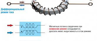
To stabilize increased traction currents and increased asymmetry currents, choke transformers are used. A choke is an inductor that can remove interference, smooth out current ripple, decouple parts of a circuit from each other at high frequencies, and also accumulate energy in a magnetic field. The device is called a “reactor” (the latter does not require the use of a drive or other driving forces, but operates on the principle of dynamics).
Thus, the main purpose of the inductor is to delay current in a certain frequency range or accumulate energy over a certain period of time in a magnetic field. The accumulated energy is used in various fields of industry and in everyday life. Let's find out more about this.
Choke transformer device
A choke-transformer is a device that ensures the passage of traction current bypassing the insulating joint.
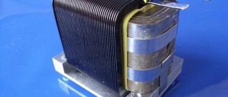
The DT device is a W-shaped core with a yoke, made of electrical steel. The main and additional windings are located on the middle rod of the core. The entire structure is placed in a cast iron housing, filled with transformer oil and closed with a lid. There are plugs on the cover through which the oil level is monitored.
In the DT device for areas with direct current electric traction, a getinax plate is provided between the yoke and the core, which provides a non-magnetic (air) gap in the magnetic circuit of the DT.
The main winding (MA) is designed for the passage of traction current and has 3 terminals, 2 of which (outer ones) are connected to the rail lines. The middle pin is connected to the middle pin of the DT of the adjacent DC.
Additional windings (AD) of the DT provide connection of devices at the relay and supply ends of the DC. And since these devices are inductively connected to the rail line, the impact on the operation of the DC of the constant component of the traction current is reduced. As a rule, the number of turns in the additional windings is greater than the number of turns in the main windings.
device, operating principle, purpose, calculation method
A path choke-transformer is a unit that passes traction current, bypassing the insulating joint. The device resembles an inductance coil, differing in design, operating principle, technical characteristics, calculation method, purpose and scope. The choke transformer is divided into types depending on the frequency and functions.
Design and operating principle
The DT device looks like a W-shaped core with a steel frame. The location of the main and secondary windings is the middle leg of the core. All components of the mechanism are immersed in a cast iron body. It, in turn, is filled with transformer oil and closed with a lid. The oil level is controlled through plugs located on the cover. The design is protected from:
- penetration into the DP by persons who are not supposed to interfere with the operation of the device;
- placing unnecessary objects on the terminals of the main winding;
- possibility of damage to the housing.
This device contains a getinax plate located in the middle of the core and frame. With its help, an air gap is ensured in the magnetic circuit of the diesel engine. The main winding is necessary to pass the traction current. It has 3 outputs. Two of them, located at the edges, are connected to the rail lines, and the remaining one in the middle is connected to the middle terminal of the choke transformer of the adjacent DC.
Additional windings are responsible for turning on the devices of the relay and supply ends of the DC. Due to the inductive connection of devices with the rail line, the operation of the DC is less affected by the constant component of the traction current.
A DC inductor transformer operates according to the principle of coil self-induction. It happens like this:
- Part of the traction current enters one half-winding of the diesel engine, moving along one rail.
- The rest of the current goes to the second half-winding of the diesel engine.
- The total current of all these parts passes through the jumper to the middle point of the OO of the adjacent DT. Divided in two, it is sent along the rails of the neighboring DC.
The device can withstand vibration ranges from low to high. The former can be from 20 Hz to 20 kHz. Average values are 20-100 kHz, and high values are more than 100 kHz. The design of high-frequency chokes is not at all similar to the design of low- and medium-frequency diesel engines.
Purpose and scope of the device
Choke transformer is used in the field of electrical engineering. It is designed for installation on railway tracks equipped with automatic AC blocking and DC electric traction. Similar equipment is used to connect electric traction systems. Throttles are also being introduced into trams, metro trains and modern high-speed railcars.
Their components are specially created for the harsh environmental conditions encountered during operation on railway transport.
If we consider the device according to its intended purpose, it is divided into the following types:
- Chokes that perform work on secondary switching power supplies. At the very beginning, the coil accumulates energy from the original source. This is done in its own magnetic field. After this, the energy is returned to the load.
- DT for starting engines. Here the device acts as a current limiter responsible for starting and braking. The choke design for drives has a power of no more than 30 kW, similar to a 3-phase transformer.
- DT saturation. It is used in voltage stabilizers and ferromagnetic converters. This kind of DT is also used in magnetic amplifiers. There, due to magnetization, the inductive resistance of the core changes.
- DT for smoothing. A similar device is used to remove rectified current ripples if there are no capacitors in tube amplifiers.
Among other things, similar devices are common in welding, interlocking, signaling and combined centralized systems.
Main technical characteristics
The characteristics contain information on the number of turns, impedance and transformation indicator of the main winding and secondary windings. Indicators of the choke-transformer DT 500:
- number of turns of the main winding – 7+7;
- number of turns of additional winding – 1560, 322, 1238;
- total resistance – 0.2-0.22 Ohm;
- transformation ratio – 40.23, 17.
Its weight is 132 kg, oil volume is 29 liters. Can last no more than 30 years. According to the rules, the core temperature should not exceed 95 C. It is determined by the temperature of the upper layers of oil.
Types of choke transformers
The most common types of choke transformers are:
- Low frequency. In appearance, it resembles a simple transformer made of iron. The only difference from it is the assembly with one winding. The coil makes it so that when the current in the circuit decreases, its value does not change and remains at the desired level, and when the current increases, the value decreases.
- High frequency. This electrical device is designed to transfer high frequency energy between 2 circuits and more by electromagnetic induction. It is much more widespread. Its coil is wound on ferrite and steel cores or on a plastic frame.
The presence of a core in the inductor increases its size. Without it, it weighs much less.
Calculation method
DT is calculated using the method of fuzzy logic, neural networks, La Grange resolvent and others. Special programs have been developed that calculate device parameters in a matter of minutes. Main stages of calculation:
- entering the required data for calculation;
- the program outputs magnetization curve values and corrects errors;
- calculation by the system of geometric parameters of the core model.
By using a special formula, you can calculate the air gap in the device on your own. It looks like this: L*I²/V. the inductance of the inductor winding is L, and the direct current on the winding is I. The letter V denotes the volume of the iron core.
Examples of calculations
For example, you can calculate LO² for an E42x21x20 core (B66329-G1000-X127) with an air gap of 2 mm, made of N27 material. The following core parameters are known and will have to be worked with:
- le = 97 mm;
- Ae = 240 mm²;
- B = 300 mT;
- Ig = 2 mm.
First you need to find the marginal coefficient F using the formula. It looks like this:
F=1+ (Ig/ Ae^1/2) *loge *(2Bw/ Ig)
The result is 1.42.
After this, you need to start calculating µe. This is effective permeability. It is found by the formula:
µe= (µo*Ae)/ (le/µi + Ig/F)
The value will be 68.
Now you need to calculate AL - the coefficient of inductive reactance. Calculation formula:
AL= (µo* µe)/(Ie/Ae)
The resulting result will be 208.
Knowing all this data, you can begin to calculate LO². For this there is the following formula:
LO²=(Bmax*Ae*Ie)/ (µo* µe)
The final answer is 16.60.
otransformatore.ru
Choke transformer: principle of operation
Choke transformers are matching transformers, which ensures that the operation of the track circuit is independent of the resistance value of the connecting wires. This is especially valuable for long RCs.
The operating principle of the DT is as follows: part of the traction current It1, passing along one of the rails, ends up in one half-winding of the DT. At this time, another part of the traction current It2 flows through the second half-winding of the diesel engine. Through the jumper, the total current It1+ It2 enters the middle point of the OO of the adjacent DT and, dividing into 2 parts, passes along the rail threads of the adjacent DC.
Created by currents flowing in the half-windings, the flows are directed in different directions. For this reason, when It1= It2, the difference flux in the core DT=0. As a result, in the DO the traction current does not induce an electromotive force (EMF).
The signal current from the power source of the track circuit enters the relay winding as follows: BEFORE the DT at the supply end is flowed around by a signal alternating current. This creates an alternating magnetic flux in the core, under the influence of which an alternating EMF is induced in the OO.
This, in turn, leads to the appearance of a signal current Ic in the rail line, which, passing through the OO of the relay DT, induces an EMF in its BO. Under the influence of this force, the travel relay I is activated (in the above diagram, the RC is an alternating current pulse relay). In this case, the DT itself at the supply end of the DC plays the role of a step-down one, and at the relay end - a step-up one (currents Ic and Itt must be different in frequency).
Safety precautions during work
When installing a track choke transformer, you should adhere to the safety and labor protection rules:
- The work is carried out by a team, one of whose members is responsible for monitoring the movement of trains. Before carrying out work, safety instructions should be given.
- Replacing the inductor transformer at the end of the rail circuit from which the power comes is done when the voltage is removed by disconnecting the wires from the transformer winding in the relay cabinet of the signal installation or removing the arms on the cross-connect stand of the electrical centralization. After the voltage is removed, using measuring instruments, you need to make sure that there is no voltage in the previously disconnected wires. At the point where the electric current is disconnected from the power supply, a prohibitory poster “Do not turn on! People are working."
- All excavation work is carried out wearing gloves.
- When carrying out loading and unloading operations, it is prohibited to be in the area of cargo manipulation.
Important! Before starting work, an uninterrupted circuit for the flow of reverse traction current should be ensured by installing temporary jumpers of the required cross-section, bypassing the insulating joints.
If a train approaches during work, you should leave the site at a safe distance in advance and remove the tool.
In emergency cases, it is necessary to provide first aid to the victim, call an ambulance and report the incident to the head of the site.
Connecting any portable meters to electrical circuits that are energized is allowed only if there are special insulated tips on the wires of the devices.
Naturally, a team that has not completed a course of special training and instructions on TB is not allowed to work.
How does the throttle work?
In AC circuits, to limit the load current, chokes - inductive reactors. Here, chokes have serious advantages over conventional resistors - significant energy savings and the absence of strong heating.
What is the design of the throttle, what is the principle of its operation based on? The structure of the inductor is very simple - it is a coil of electrical wire wound on a core made of ferromagnetic material . The prefix ferro indicates the presence of iron in its composition (ferrum is the Latin name for iron), in one quantity or another.
Without a choke, the circuit will work as usual - the circuit closes, the lamp lights up. But if you add a choke, connecting it in series with the load (light bulb), the picture will change somewhat. Taking a closer look, you can see that, firstly, the lamp does not light up immediately, but with some delay, and secondly, when the circuit is opened, a clearly visible spark appears, which has not been observed before. This happens because, at the moment of switching on, the current in the circuit does not increase immediately - the inductor prevents this, absorbing electricity for some time and storing it in the form of an electromagnetic field . This ability is called inductance.
The larger the inductance value , the more energy the inductor can store. The unit of inductance is 1 Henry. At the moment the circuit breaks, the stored energy is released, and the voltage can exceed the E.M.F. of the source used tens of times, and the current is directed in the opposite direction. Hence the noticeable sparking at the rupture site. This phenomenon is called E.M.F. self-induction.
If you install an AC source instead of a DC one, using, for example, a step-down transformer , you may find that the same light bulb connected through an inductor does not light up at all. The inductor provides much greater resistance to alternating current than to direct current. This occurs due to the fact that the half-cycle current lags behind the voltage.
Graphically it looks like this.
It turns out that the effective voltage across the load drops many times (and the current accordingly), but energy is not lost - it is returned through self-induction back into the circuit. The resistance provided by inductance to alternating current is called reactive . Its value depends on the magnitude of the inductance and the frequency of the alternating current. The amount of inductance, in turn, depends on the number of turns of the coil and the properties of the core material, called magnetic permeability , as well as its shape.
Throttle designation on the diagram
Such details are always depicted according to a single principle, so it is enough to understand it once in order to then regularly read such diagrams. In this case, the number of semicircles can be chosen almost arbitrarily; more often it is 3 or 4 units for convenient pairing with other elements. The winding leads are directed in one or different directions, it all depends on the configuration of the circuit. If you need to depict a bend, then draw joints of semicircles next to each other, without putting a dot between them.
There is also color marking of parts that corresponds to inductance values. The first few marks indicate inductance values in µH. The third is the multiplier, and the last is the available tolerance. Chokes are marked using 3 or 4 stripes, sometimes they are changed to dots. If there are three marks on a part, the default tolerance is 20%.
Chokes are used not only in different types of light bulbs, but also during the assembly of switching power supplies, in which they act as a filter. In electrical circuits it is more often called a reactor, but the principle of the device remains the same. The part is also put into welding machines and used for industrial purposes.
How does a transformer work?
Let's consider the operation of a choke assembled on a closed magnetic circuit and connected as a load to an alternating current source. The number of turns and the magnetic permeability of the core are selected in such a way that its reactance is high, but the current flowing in the circuit is correspondingly not.
The current, periodically changing its direction, will excite an electromagnetic field in the winding of the coil (let's call it coil number 1), the direction of which will also periodically change - reversing the magnetization of the core. If an additional coil is placed on the same core (let’s call it number 2), then under the influence of the alternating electromagnetic field of the core, an induced variable E.M.F. will appear in it.
If the number of turns of both coils is the same, then the value of the induced E.M.F. very close to the value of the voltage of the power source applied to coil number 1. If the number of turns of coil number 2 is halved, then the value of the induced E.M.F. will decrease by half, if the number of turns is the opposite, increase - the induced E.M.F. will also increase. It turns out that for each turn there is a certain part of the voltage.
The winding of the coil to which the supply voltage is applied (number 1) is called primary , and the winding from which the transformed voltage is removed is called secondary .
The ratio of the number of turns of the secondary (Np) and primary (Ns) windings is equal to the ratio of their corresponding voltages - Up (primary winding voltage) and Us (secondary winding voltage).
Thus, a device consisting of a closed magnetic circuit and two windings in an alternating current circuit can be used to change the supply voltage - transformation. Accordingly, it is called a transformer .
If you connect any load to the secondary winding, a current (Is) will arise in it. This will cause a proportional increase in current (Ip) in the primary winding. The following ratio will be correct:
Transformers can be used both to convert the supply voltage and to decouple and match amplification stages. When working with transformers, it is necessary to pay attention to a number of important parameters, such as: 1. Permissible currents and voltages for the primary and secondary windings. 2. The maximum power of the transformer is the power that can be transmitted through it for a long time without causing overheating of the windings. 3. Operating frequency range of the transformer.
Transformers and chokes.
A transformer is an electromagnetic device for converting the basic parameters of electrical energy in alternating current circuits. Chokes come in high-frequency and low-frequency types. A choke is a device that serves to reduce the ripple resulting from rectification of alternating current and is used as filters and rectifiers. RF/chokes are devices designed to reduce the high frequency current passing into any circuit, while maintaining the ability for low frequency or direct current to pass. 6.1 Classification of transformers.
Transformers are classified according to their power, current, operating frequency,
voltage, operating mode, purpose and location in the circuit.
Based on voltage, transformers are divided into low and high voltage. Working
voltage characterizes the value for which the insulation must be designed
or one, several or all windings of the transformer. To high voltage
These include transformers in which the operating voltage in any winding is not
exceeds 1000 - 1500V.
Such transformers are divided into 2 types:
1) has a high rated voltage (over 1500V) and reliable insulation between the individual windings of the transformer or between each winding and the housing, as well as reliable layer insulation in high-voltage windings.
2) It has a low operating voltage in the windings, but due to the circuit design, high voltages exist between the windings or between some winding or housing. In this case, transfer. It is considered high-voltage because it requires high-voltage insulation between the winding and the housing. However, in this case low voltage is used.
6.2 Scope of transformers.
Power transformers are used to obtain voltages supplying rectifiers, motors and other loads (about 70% of all devices)
Low-frequency transformers are used as a matching element between a signal source and the input of an amplifier, between two amplifiers, or between an amplifier and a load.
A special group consists of pulse transformers, which are used to transform or generate short-duration pulses. They are used in pulse technology, sonar, and in circuits of ultrasonic devices and installations. In pulsed mode, their power reaches high values. Chokes are used in power filters (smoothing chokes), in rectifier filters, in high-frequency filters, in various selective circuits, in various stabilizers and regulators.
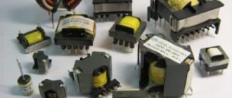
6.3 Structural elements of transformers and chokes. Despite the differences in the functions of power transformers and low-frequency transformers, the basic physical processes occurring in them are the same. Therefore, transformers for different circuit purposes have the same type of design: any transformer consists of a core made of magnetic material on which a coil with windings is placed, as well as elements that serve to fasten parts of the core and secure the transformer. 6.3.1 Magnetic cores.
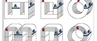
For transformers and chokes, three spikes of magnetic cores are used: rod, armored and ring.
When using an armored magnetic circuit, all windings of the transf. placed on one coil, which is put on the middle rod of the magnetic circuit.
When using a rod, there are 2 coils located on its 2 rods.
In low-power power and low-frequency transfers. An armored core is used, because the use of one coil simplifies the design and allows for maximum gain; it is filled with copper.
The rod structure is used for transfer. medium and high power: the presence of two coils increases heat transfer and improves the thermal conditions of the windings.
The advantage of the rod design system is a weak external magnetic field, since the fields from these coils are directed towards each other. The smallest external field is obtained when used in transf. ring magnetic cores. But they are rarely used because the performance is low when the magnetic circuit breaks down.
According to their design, armored and core magnetic circuits are divided into those assembled from film plates and film ones.
A strip magnetic core can be obtained by pouring and winding a strip of a transformer system. After cutting, C-shaped cores are obtained.
To get min. After installing the magnetized gap in the magnetic circuit, the ends of the cores are filled with a paste containing ferromagnetic material. If a gap is necessary, then overlays made of paper or cardboard of the required thickness are installed in the place where the two cores are cast. The tape design of the cores makes it possible to mechanize the manufacturing process.
When using non-commutated steels, the use of strip cores makes it possible to maintain the size and weight of transformers. This happens because the magnetic field lines run perpendicular to the direction of the flow. In this case, you can have quite large sizes. In strip cores, the field lines are located along the entire length of the magnetic circuit.
The main parameters of the core include: the average length of the magnetic field line 1c, the active cross-sectional area of the magnetic core Sc, the window area So, and the weight of the magnetic circuit Gc.
Cross-sectional area
Sc
= kc
*
2 ab
where kc is the filling factor, taking into account that part of the cross-sectional area of the magnetic circuit is occupied by metal oxide and other magnetized materials.
Kc - depends on the thickness of the material and lies within 0.85 < k c <
0.95
Transformers.
GOST 17596 - 72 - matching transformers, low-frequency power up to 25
Tue
Main parameters:
Terms and Definitions.
Rated power - the calculated total power of the secondary windings at rated voltages and load resistances in matching mode.
Rated load resistance is the resistance for which the transformer is designed.
Transformation ratio is the ratio of the number of turns of the secondary winding to the number of turns of the primary or the voltage on the secondary winding to the voltage on the primary winding. In idle mode, the voltage drop across the transformer will be taken into account.
studfile.net
Parallel oscillatory circuit.
If you connect an inductor and a capacitor, you get a very interesting element of radio engineering - an oscillatory circuit. If you charge a capacitor or induce E.M.F. in the coil using an electromagnetic field, the following processes will begin to occur in the circuit: The capacitor, when discharged, excites an electromagnetic field in the inductor. When the charge is depleted, the inductor returns the stored energy back to the capacitor, but with the opposite sign, due to the E.M.F. self-induction. This will be repeated again and again - electromagnetic oscillations of a sinusoidal shape will appear in the circuit. The frequency of these oscillations is called the resonant frequency of the circuit, and depends on the values of the capacitor capacitance (C) and the inductance of the coil (L).
A parallel oscillatory circuit has a very high resistance at its resonant frequency. This allows it to be used for frequency selection (selection) in the input circuits of radio equipment and intermediate frequency amplifiers, as well as in various master oscillator circuits.
Calculator for calculating the inductance of a single-layer coil.
The use of any materials from this page is permitted provided there is a link to the “Electrical is Easy” website.
To stabilize increased traction currents and increased asymmetry currents, choke transformers are used. A choke is an inductor that can remove interference, smooth out current ripple, decouple parts of a circuit from each other at high frequencies, and also accumulate energy in a magnetic field. The device is called a “reactor” (the latter does not require the use of a drive or other driving forces, but operates on the principle of dynamics).
Thus, the main purpose of the inductor is to delay current in a certain frequency range or accumulate energy over a certain period of time in a magnetic field. The accumulated energy is used in various fields of industry and in everyday life. Let's find out more about this.
Principle of operation
The principle of operation is based on the principle of self-induction of the coil. The design of the device contains only one winding, but due to the principle of operation and scope of application, the device is often called a choke transformer.
The coil of the device consists of plates insulated between each other (most often steel or ferromagnetic). Isolation is carried out to avoid the formation of Foucault currents, which create interference. The core has a high inductance, but at the same time it is a powerful restraining barrier (for example, during a strong increase or decrease in voltage in the network).
The device is able to withstand various vibration ranges:
- low (from 20 Hz to 20 kHz);
- medium (or ultrasonic, from 20 to 100 kHz);
- high (over 100 kHz).
High-frequency chokes differ in design from low- and mid-frequency ones.
Varieties
Devices are divided into:
- The low-frequency choke-transformer looks similar to a primitive iron transformer. The difference is the single winding layout. The coil provides significant resistance to changes in current in the circuit - when it decreases, the device is able to maintain the required level, and when it increases, it is able to reduce it.
- High frequency circuits are more common. The coils of such devices are wound onto cores (ferrite, steel) or onto a plastic frame. When working with medium or long range waves, sectional winding is often used.
A choke with a core has smaller dimensions than one without it.
The main parameters of the device are inductance (unit of measurement - H) and resistance (Ohm). Important characteristics are voltage, rated current and quality factor.
Type of chokes
There is a wide range of fluorescent lamps on the market. And each type of fluorescent lamp has its own choke transformer. For example, a DRL lamp and a HPS lamp cannot be lit by the same type of throttle. It's all about different parameters for starting and maintaining combustion. Here the voltage and current are different.
But the MGL lamp can operate both from the choke of the DRL lamp and from the HPS. But there is one point. The brightness of this light source will depend on the applied voltage. And the color temperature will be different.
Attention! Any choke transformer will “outlast” several lamps in terms of its service life. Of course, with the caveat that the lamp is used correctly.
Varieties of chokes
But you have to take into account the fact that the lamp “gets old” over the years. A special alkali metal paste is applied to the tungsten electrodes of fluorescent fluorescent lamps. So this paste gradually evaporates, the electrodes are exposed, and, therefore, the voltage increases, which leads to overheating of the inductor. The end result can be two options:
- The coil winding will break, which will cut off the voltage supply to the electrodes.
- The coil will short-circuit. And this is connecting the lamp directly to the AC mains. The lamp will burn out - that’s for sure, or it may explode, which will lead to damage to the lamp as a whole.
Therefore, my advice is not to wait for the lamp to burn out on its own. There is a special replacement schedule that is determined by the manufacturer, and which must be strictly adhered to. When carrying out preventive maintenance, experienced electricians must check these lighting devices for the voltage parameter. If it approaches the normal limit, then the lamp is changed before its service life. It is better to replace an inexpensive lamp than an expensive choke transformer.
Scope and purpose of DC chokes
Devices, for example, the choke-transformer DT-0.6-1000, are intended for installation on railway tracks that are equipped with automatic AC blocking and DC electric traction. Also, devices of this type are used for joining electric traction systems.
According to their purpose, choke transformers are as follows:
- Chokes that operate on secondary switching power supplies. First, the coil accumulates energy from the primary source in its own magnetic field, and then returns it to the load.
- Chokes for starting engines. In this case, the devices act as a limiter of starting and braking currents. For drives whose power does not exceed 30 kW, the design of the choke is similar to a three-phase transformer.
- Saturation choke. It is used in voltage stabilizers and in some converters (for example, ferroresonant). The device is also used in magnetic amplifiers, where the core changes the inductive reactance of the circuit by magnetization.
- Smoothing chokes. They are used to eliminate rectified current ripple (for example, in the absence of capacitors in tube amplifiers).
The devices are also widely used in welding, when installing lighting, in alarm systems, centralization, automatic blocking, mechanics, etc.
Railway choke transformers: technical characteristics | SCB Service
The DT inductor transformers presented in the section are intended for installation on electrified sections of railways, equipped with electric traction on direct or alternating current with a frequency of 50 Hz and electrical blocking on signal alternating current with a frequency of 25 Hz and 75 Hz in the track circuit (RC). Additionally, the choke-transformer performs the function of connecting 2 electric traction systems.
The choke transformer railway is designed to transmit the rated current in electric traction through each section of the main winding. The throughput of the middle output of the DT is designed for double the current strength.
The DG choke brand DG-150 and the choke-transformer DT-1-150 pass a rated alternating current of 150 A. The average output is 300 A.
The DG choke type DG-300 and the transformer choke DT-1-300 pass, respectively, a current of 300 A. The average output is 600 A.
Overall dimensions of DG-150 and DG-300: 388×514×207 mm; DT-1-150 and DT-1-300: 535×335×325 mm. Both types of diesel engines have transformation coefficient of 3.
The dual choke railway transformer 2DT-1-150 consists of two DT-1-150 enclosed in one housing. Each of the 2 DTs consists of a core, 2-section main winding and an additional winding. The number “150” in the choke-transformer brand indicates that the capacity of this DT is 150 A, the middle output is 300 A (similar to the designation of the capacity of chokes and choke-transformers of other types).
Accordingly, the dual choke transformer 2DT-1-300 consists of two DT-1-300 enclosed in one housing. Throughput - 300 A, middle output - 600 A.
The dimensions of 2DT-1-150 and 2DT-1-300 are as follows: 520x520x310 mm. Transformation coefficient - 3.
Choke transformers DT-0.2-500 or -1000 and DT-0.6-500 or -1000 transmit a long-term traction current of 500 A or 1000 A through each section of the main winding. The middle terminals are designed, respectively, to pass a current of 1000 A or 2000 A.
If the transformer choke has the letters “M” and “G” in its marking, this indicates that this DT does not require oil filling and is equipped with a sealed winding filled with sealant.
Overall dimensions DT-1MG-150 and DT-1MG-300: 460×535×208 mm; 2DT-1MG-150 and 2DT-1MG-300: 530×515×208 mm. The main winding consists of 2 half-windings, each of which has 8 turns. The signal winding has 48 turns.
Return to "Articles"
scbservice.ru
Basic elements of the device. Specifications
The main elements of the device are:
- core;
- yoke;
- cast iron body;
- lid;
- coupling;
- pipe;
- additional winding;
- seal.
The technical specifications indicate: the number of turns, impedance and transformation ratio in the main and additional windings. For example, in a DT 500 inductor transformer the number of turns of the main winding is 7+7, the additional winding is 1560, 322, 1238. The total resistance is 0.2–0.22 Ohm, and the transformation ratio is 40, 23 and 17.
Difference between devices by color marking
Each electronic choke transformer device is marked depending on its parameters. To make it easier to decipher long and complex abbreviations, color coding was introduced.
The latter is a code of several colored rings that determine the inductance of the device. The first two show the nominal inductance, the third is the multiplier, and the last is the tolerance. Such differences allow even a novice master to easily determine the appropriate device.
Important! If only 3 rings are shown on the throttle, then its tolerance is 20%.
Device
The transformer choke has the form of a conductor that is wound in a spiral. Depending on the scope of use, it is made single- or multi-core. Sometimes a dielectric frame is added to the device or the part is left without it. Some elements additionally use a base with a round, square or rectangular cross-section.
The part consists of many turns; during creation, progressive or universal winding is used. When using the first type, they change smoothly along the entire length, while the second type - the distance between the turns remains the same.
Progressive winding is used in electrical engineering when it is necessary to construct a high-frequency device. To achieve the result, it is necessary to reduce the parasitic capacitance. Winding is carried out in one or several layers; only copper is suitable as a material, since it acts as a conductor.
To increase the inductance, a ferromagnetic core is used. Depending on the application, different types of material are used, since some of them are suitable for suppressing strong interference, while others are used for filtering sound. When throttling of mechanisms at ultra-high frequencies is required, brass is mainly used.
During production, the manufacturer takes into account the required inductance, current carrying capabilities and induction features, since otherwise saturation will occur. First, the size of the gap, the number of turns and the current strength are determined, and then the diameter of the wire is calculated. In small machines or electronic devices, the inductor is made flat, then the conductor is arranged in a circle or zigzag.
The design of the throttle and its purpose using the example of a railway track
AC track circuits are installed on some sections of railways. In these (electrified) sections, the contact wire is the direct conductor of current to electric locomotives, and the return lines are the rail threads and the ground.
In the case when current is passed through both rail threads, the AC rail circuit being installed is called a two-thread one. In this case, the purpose of the inductor transformer is to pass the reverse traction current bypassing the insulating joints on each side. Each device has two windings: main and additional.
While the train is moving, current flows through both halves of the inductor transformer winding, then the currents collide at the midpoint and branch out again in the direction of the traction substation. Correct installation of devices ensures that traction current does not influence the equipment.
Maintenance-free DC choke transformers type DTE
02.10.2015
Choke-transformer type DTE is a modern DC choke-transformer that does not require additional maintenance. Unlike its predecessors, it is completely sealed.
The body of the inductor transformer is made of fiberglass, filled with a thermally conductive compound from the inside. Fiberglass prevents the possibility of breakdown of insulation on the body and does not require additional painting in black. The housing of the DTE choke transformer has a thermally conductive filler. All this eliminates the need to monitor the level of cooling oil and its quality during operation.
In addition, each DTE choke-transformer is equipped with an anti-vandal casing. The terminals of the main winding are protected from foreign objects.
The DTE choke-transformer has 2 windings - the main and additional. Traction and signal currents are passed through the main one. Through the additional one - passing the signal current and connecting the RC signaling equipment.
Low-maintenance (maintenance-free) DC choke-transformers of the DTE type are produced in the following versions:
- DTE-0.2-500; n=17, 23, 40
- DTE-0.2-1000; n=17, 23, 40
- DTE-0.2-1500; n=17, 23, 40
- DTE-0.4-1500; n=3, 15, 38
- DTE-0.6-500; n=3, 15, 38
- DTE-0.6-1000; n=3, 15, 38
- DTE-0.6-1500; n=3, 15, 38
Application of DTE choke transformers
DTEs have a standard application and are operated in signaling systems of railway transport.
DTE-0.2-500(1000) and DTE-0.6-500(1000) are used in track circuits with a frequency of at least 50 Hz. In the voice frequency center - up to 1000 Hz, they are switched on using an additional winding. With a tonal frequency above 1000 Hz, DTE-0.2-500(1000) and DTE-0.6-500(1000) should be connected to the DC without additional winding.
Choke transformers DTE-0.2-1500, DTE-06, -1500 and DTE-0.4-1500 are used in track circuits with increased traction currents and asymmetry currents in sections with a frequency of 50-1000 Hz.
At NKA-StroyService you can buy DTE and DT choke transformers of the desired type, as well as order delivery to the destination and installation at the site of operation.
nkass.ru
Throttle calculation
The methods for calculating a choke transformer use methods of fuzzy logic, neural networks, La Grange resolvent, etc. Modern programs allow you to calculate the necessary parameters of the device in just a few minutes. The entire calculation process consists of the following stages:
- The necessary data is entered (magnetization curve points, core material, etc.).
- Next, the program provides data on the magnetization curve, corrects values and errors.
- The system calculates the geometric parameters of the core model.
The air gap in the device can be calculated independently using the formula:
L – inductance of the inductor winding, H;
I is the strength of direct current passing through the winding, A;
V is the volume of the iron core.
The value ∂, which is necessary to calculate the gap of the steel core, is found using a special nomogram.
For example, under the conditions that L = 20 H, I = 60 mA, V = 40 cm 3, then
L•I 2 /V= 10•3600•10-6/40 = 9•10 -4.
The nomogram determines the value ∂ = 20•10-3 = 0.2 mm.
Based on this, the gap on each side should be 1 mm.
Operating principle of the filter choke
A smoothing choke or filter choke is a component of an electronic circuit designed to reduce the alternating component of voltage or current at the input or output of a circuit. As a rule, it consists of a closed magnetic circuit (core) and one winding. The inductor winding is connected in series with the load
Filter choke connection diagram.
This type of choke is most often included in complex multi-section filters. Its action is based on the fact that the active winding resistance rdr is much less than the load resistance RN, and the inductive resistance Xdr at the pulsation frequency f is much greater than the load resistance
Thus, representing the voltage at the inductor input Uin as the sum of a constant U0 and an alternating component U~, we can conclude that almost the entire constant component will be applied to the load, and the alternating component to the inductor.
The quality of any filter is assessed using the smoothing coefficient, which for a smoothing choke is determined by the expression
From this expression, by the required value of the smoothing coefficient q, you can determine the required value of the inductor inductance L.
How to make a throttle yourself
In order to make a transformer from a choke yourself, you need to calculate the number of turns per volt for the existing core. Then the inductor is carefully disassembled and the process of winding the future transformer is carried out. During assembly, it should be taken into account that the gap that was present in the throttle before disassembly must be eliminated.
You can also make a transformer from chokes. The amount of material used directly depends on the purpose of the invention.
Physical processes in the inductor core
As already mentioned, a smoothing choke is a coil with a ferromagnetic core, which significantly increases the magnetic field, so all the characteristics of the choke are determined by the properties of the core. At the same time, the properties of the core depend on the current IL flowing through the inductor. This current can be represented as the sum of a constant component I0 and an alternating component I~.
Current flowing through the filter choke.
In this regard, two parameters of the pulsating current can be distinguished: the amplitude value of the current Imax and the effective value of the current I, which are determined by the following expressions
where I0 and I~ are, respectively, the amplitude of the constant and variable components of the pulse current flowing through the smoothing choke,
kf – coefficient of the current shape of the alternating component.
Let's consider the effect of pulsating current on the parameters of the core. The figure below shows the core magnetization curves for two modes: in the absence of magnetization (I0 = 0) and with direct current bias (I0 > 0).
Throttle operation during magnetization.
The figure shows curves of changes in the magnetic field induction in the core when it is magnetized by a sinusoidal current in two operating modes: without magnetization (curve 1) and with magnetization by direct current I0 (curve 2). As is known, when the core is periodically magnetized, the magnetic induction B changes not along the main magnetization curve, but along closed curves called magnetization reversal loops (highlighted in red). In the first case, when there is no bias, the loop is symmetrical with respect to the main magnetization curve (loop 1). In the case of the presence of bias current I0, the magnetization reversal of the core occurs along the so-called private magnetization reversal loops (loop 2). Partial magnetization reversal loops are characterized by an increased area, which means an increase in losses in the core (the area limited by the loop is equal to the power losses in the core).
In addition to the increase in losses when the core is saturated, there is a decrease in the magnetic permeability of the core material. Since the inductance of the inductor L has a direct dependence on the magnetic permeability, therefore there is a decrease in inductance.
The equivalent permeability of a substance μe is determined from the relationship between the induction B created by the magnetic field and the intensity H of a given magnetic field
where ω is the number of turns of wire in the winding,
I – current through the inductor.
The inductance of the inductor can be determined by the following expression
where ω is the number of turns of wire in the winding,
μ0 – magnetic constant, μ0 = 4π*10-7 H/m,
μе – equivalent (relative) magnetic permeability of the core,
Sе – equivalent cross-sectional area of the core,
lе – equivalent length of the magnetic line of the core.
lM – length of the magnetic line in the core.
Technological process for replacing a choke transformer
Reinstallation and removal of the choke transformer is carried out in the following order:
- After receiving permission to carry out the work, the power supply is removed.
- Next, the protective casing is dismantled.
- After carrying out the above operations, the insulating cable entry pipe should be freed from the soil and the cable stock should be cleaned.
- Next, unscrew the nuts of the mounting bolts and remove the cover of the cable rack.
- Then the cable cores are disconnected and the cable is pulled out from the insulating pipe post.
Installation of electric traction connectors bypassing is carried out in the following order:
- One connection of the throttle plug-jumper and the rail is dismantled on both sides of the insulating joints, to do this, unscrew and remove the lock nut on each of them, unscrew the nut to the end of the thread, knock the plug out of the rail, and disconnect the jumper from the rail.
- Install connector plugs into the vacated holes. Screw the nuts onto them and secure them until they stop.
Installation and assembly of the choke transformer is carried out in the reverse order of dismantling work.
Important! Before installation, you should carefully read the instructions and work procedure. It is necessary to take into account the installation location of the choke (at the supply end or in sections) depending on its type and purpose.