Scope of application and features
Face mills are used on vertical milling machines for finishing of planes, grooves, ledges, as well as various shaped surfaces of complex configuration. The main area of application is mechanical engineering - boring of shafts, gears and other parts. The tool allows you to simultaneously process two surfaces located at right angles to each other thanks to the cutting edges on the end and cylindrical surfaces. To increase processing efficiency, proper selection of the body, cutting speed, replaceable inserts, lubricants and coolants is necessary.
During processing, only the tops of the edges are profiled. The shapes of the cutting elements can be varied, most often they are made in the form of a circle or a broken line. The shape and location of the cutting parts allows for smooth processing with minimal allowance, the value of which does not affect the angle of contact with the workpiece. The main parameters are the diameter of the cutter and the width of the cut. A necessary condition for face machining is high rigidity and dimensions of the tool, so the fastening of the tooth and replaceable inserts is especially strong.
Design and classification of cutters
The main structural parts of the cutter include its body 4 and cutting teeth 5 with certain sizes and shapes (Fig. 1).
Based on the arrangement of the teeth on the body, cylindrical and end mills are distinguished.
Figure 2
Figure 3
Cylindrical cutters
have teeth on the forming surface of the body, their structural elements are: front surface 7, rear surface 8, back 1, cutting edge 9 (Fig. 1a).
Face milling cutters
equipped with teeth on the end surface of the body, including the following elements: front surface 7, main rear surface 11 (in the figure facing down), as well as the main cutting edge 9, auxiliary cutting edge 12 and apex 10 (Fig. 1b).
The front surface of the tooth absorbs the load from the chips flowing along it, the main rear surface is in contact with the cutting surface 2, the auxiliary rear surface is in contact with the machined surface 3, improving its quality.
The required milling performance is achieved by increasing the depth t, feed S and processing speed V. In order to ensure the specified durability of cutters, tool materials with high hardness, strength, wear resistance, heat resistance, but also with increased cost are used for their manufacture.
According to the manufacturing method, cutters are divided into solid, composite and prefabricated.
Solid cutters
are made from tool low-alloy steels KhG, KhVG, KhV5, 9KhS with low heat resistance and are used in repair and small-scale production of parts at cutting speeds of up to 25 m/min (Fig. 3a, 4a, 6a).
Compound cutters
have a working part 1 made of tool, high-alloy high-speed steel R12, R6M3, R6M5, R9K5, and a shank 2 made of structural carbon or alloy steel (Fig. 6b). The working part and the shank are connected by welding, which makes it possible to reduce the cost of cutters and, due to the increased heat resistance of the material of the working part, use them in large-scale production at cutting speeds of up to 100 m/min.
Prefabricated cutters
are equipped with cutting teeth (knives) made of high-speed steel, as well as teeth made of structural alloy or instrumental carbon steel with cutting plates made of instrumental hard alloy. The cutting knives are held in the slots of the cutter body due to mechanical fastening (Fig. 3b, 4b). Carbide cutting inserts 3 are usually mounted in socket 6 of the body, knife or working part of the cutter (Fig. 3c, 4c, 6c).
Figure 4
The cutting blades are pressed and sintered from a mixture of cobalt and tungsten carbide powders (VK6, VK8, VK10M) with titanium carbide (T5K10, T14K8, T60K6) and titanium carbide (TT7K12, TT20K9). The high heat resistance of these materials has ensured the widest use of prefabricated carbide cutters in mass production at cutting speeds of up to 800 m/min. For finishing processing, plates made from a mixture of powders based on corundum at2O3
– mineral ceramics grades V0-13, V0-14, VOK-60, VOK-63, which allows several times to increase the productivity and durability of the cutter.
Based on the method of attachment to the machine spindle, a distinction is made between attachment and shank cutters.
Shell cutters
They have a central hole with a keyway (Fig. 1a) or an end groove (Fig. 1b), which allows them to be installed on a mandrel, which is then fixed in the machine spindle.
Shank cutters
equipped with a tapered shank 2, with which the cutter is installed and secured in the tapered hole of the adapter sleeve or machine spindle (Fig. 6).
Based on the position of the cutting edge of the teeth relative to the cutter axis, cutters with straight, helical and multidirectional teeth are distinguished.
Straight cutters
They are simple to manufacture, but each tooth enters and exits the cutting process with its entire width at once, which makes cutting uneven, reduces the durability of the cutter and the quality of the machined surface (Fig. 5a, b).
Helical cutters
have teeth with cutting edges directed at an angle to the cutter axis (Fig. 3, 6). During operation, such teeth cut into the material and exit the cutting process gradually along their width, which stabilizes cutting, increases the durability of the cutter and the quality of processing. When installing a helical cutter, the direction of the helical line of its teeth and the direction of rotation of the spindle (right or left) must be opposite, so that the axial component of the cutting force is directed towards the spindle socket, eliminating loosening of the mandrel with the cutter in it.
Multi-directional teeth
During operation, cutters create cutting forces, the axial components of which are oppositely directed and balance each other (Fig. 5f).
Based on the shape of the back surface of the teeth, cutters with pointed teeth and those with backed teeth are distinguished.
Figure 5
Pointed tooth
has a straight or parabolic shape of the line of the rear surface along which it is sharpened (Fig. 5a). Cutters with such teeth are easy to manufacture and have high durability, but regrinding them greatly changes the profile of the teeth, which does not allow the use of such cutters for processing shaped surfaces.
Backed tooth
characterized by a back surface line made along an Archimedean spiral (Fig. 5b). Its production is more complex, and regrinding is carried out along the front surface, such as cutters for processing shaped surfaces.
Based on the number of teeth and their pitch, cutters are divided into coarse-tooth and fine-tooth.
Coarse cutters
They have high strength and durability, but create an uneven milling mode (Fig. 5d). This deteriorates the quality of processing and allows them to be used for rough milling.
Fine tooth cutters
ensure uniform operation and high surface quality during finishing milling (Fig. 5c).
According to the type of work performed, cutters for processing flat surfaces, grooves and shaped surfaces are distinguished.
Flat surfaces are machined with cylindrical, face, disk or end mills.
Cylindrical cutters
usually have helical teeth and are made in one piece (Fig. 3a), as well as assembled with insert knives made of high-speed steel (Fig. 3b) or with screw plates made of carbide (Fig. 3c). Wide surfaces are processed by a set of cutters, and the directions of the helical lines of the teeth of the cutters in the set should be such that the axial components of the cutting forces would tend to bring the cutters closer together or their resultant would be directed towards the machine spindle (Fig. 3b).
Face milling cutters
can be solid (Fig. 4a) or prefabricated with inserted knives made of high-speed steel (Fig. 4b) or equipped with hard alloy plates (Fig. 4c).
Disc cutters
They are manufactured in one piece or prefabricated and, according to their purpose, are divided into grooved (Fig. 5a, b), cut-off and slotted (Fig. 5c, d), double-sided (Fig. 5e) and three-sided (Fig. 5f). Surfaces in the form of ledges are processed with double-sided and three-sided cutters, deep grooves are processed with three-sided cutters with multi-directional teeth to improve chip removal and increase the durability of the cutter.
The end cutting edges of disc cutters are beveled to reduce friction forces on the back surface. Because of this, after regrinding, the width of their teeth decreases, which can be compensated by using a set of cutters with an adjustable set width.
Through, through, closed and T-shaped grooves are machined with disc groove cutters, slotting and parting cutters, as well as end and key cutters.
Slot cutters
with pointed or backed teeth on the forming surface, they are used for processing shallow grooves that are precise in width (Fig. 5a, b).
Slotted
(slotted) and cut-off cutters are used to produce narrow, shallow slots (screw head splines), as well as to cut the workpiece to a given size (Fig. 5c, d).
End mills
can be solid, composite or prefabricated with a crown or screw plates made of hard alloy (Fig. 6). End mills are used to machine vertical surfaces, ledges, and deep grooves of complex configurations. Solid and composite cutters have ground teeth with chip separating grooves for improved cutting conditions. They are used for pre-treatment and are often called "corn".
Key cutters
for processing grooves, feather keys can be made solid from hard alloys, solid or composite from high-speed steel, as well as prefabricated with carbide plates (Fig. 7a). For grooves of segment keys, keyed shank, solid or composite cutters are used (Fig. 7b), as well as keyed mounted solid cutters (Fig. 7c).
T-shaped grooves are formed by solid, composite or assembled cutters with carbide plates (Fig. 8).
Shaped surfaces are formed by curves, and their profile is usually concave, helical or serrated.
Semicircular
Concave (Fig. 9a) or convex (Fig. 9b) cutters of solid construction with backed teeth are used to produce protrusions or grooves of a semicircular profile.
Thread cutters
can be disk or comb teeth, corresponding to the profile of the thread being cut. Disc cutters with pointed teeth are used for cutting long trapezoidal threads, for example, the lead screw of machine tools (Fig. 10a). Comb cutters have backed teeth and are used for cutting external or internal triangular threads of short length (Fig. 10b). They are manufactured as tail-mounted, one-piece or composite designs, or as one-piece attachment ones.
Figure 6
Figure 7
Figure 8
Figure 9
Figure 10
Figure 11
Gear cutters modular cutters
They are divided into disk, finger and worm; they have backed teeth with a profile corresponding to the profile of the gear surface being cut. Disc modular cutters are designed for cutting spur wheels and racks using the gear copying method (Fig. 11a). They have a one-piece structure made of high-speed steel or carbide. Finger modular cutters are used for cutting cylindrical and conical spur, helical and chevron wheels using the gear copying method (Fig. 11b). They are manufactured in one piece, composite or prefabricated. Hob modular cutters are used for cutting cylindrical and bevel gears with straight, oblique and spiral teeth using the gear rolling method (Fig. 11c). They can be solid from high-speed steel or hard alloy, as well as prefabricated with inserted comb knives made from high-speed steel or hard alloy.
Types of tools
End mills require a large volume of work, which requires a variety of design options to solve the task. First of all, cutters are divided according to the material of the cutting part of the cutter, which is used as:
- High-speed and carbon steels.
- Hard alloys.
- Mineral ceramics.
- Industrial diamonds (for non-metallic hard materials).
Depending on the design, cutters can be prefabricated or solid. The former have removable carbide teeth or plates, which allows sharpening or replacement as they wear out. According to the shape of the tooth tips, the tool can be rounded or straight. Rounded ones have higher performance characteristics due to minimal runout of edges during cutting and high wear resistance. Rounded teeth are used for roughing or semi-finishing.
Depending on the method of fastening, end mills are divided into end mills and shell mills. With end fastening, installation is carried out on the shank; the attachment ones are mounted on a frame with a key. The latter are usually used for working with steel and cast iron parts, for preparing ledges and planes. The material of shell cutters is usually high-speed steel.
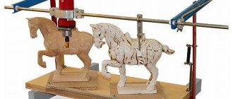
Figurine cutters
The tool is used in the manufacture of panels, namely for decorative processing of the edges of parts. All equipment has a thrust bearing fixed at the bottom. A cutter with a bearing can process not only rectangular workpieces, but also shaped ones. You should know that paneling tools have a diameter of 50 to 70 m, so in order to use them effectively, you must have a device with a power of at least 1500 W. For a household router, processing panels with this type of equipment will be an impossible task.
To make doors using a manual milling cutter (meaning kitchen facades), you will need to purchase a special set consisting of three elements.
The set contains the following facade cutters: one panel cutter and two accessories for furniture trim (profile-counter-profile).
Horizontal
Used for pre-treatment of panels. To form a tenon for insertion into the frame groove, additional processing of the edge will be required.
Vertical
Most often, vertical figurine cutters are used to make baseboards.
Horizontal double-sided
This type of equipment significantly simplifies the production process, since in one pass of the tool a connecting tenon and part of a panel of a certain configuration appears on the edge.
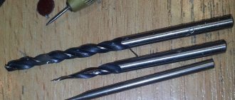
In addition to the above types of equipment, many craftsmen also use homemade cutters. They are usually standard plumbing drills, sharpened in a special way. You can learn how this is done at home from the video.
Stone cutters
To process artificial stone with a milling cutter (manual), you can use traditional types of cutters designed for wood, but only with carbide blades . There is one nuance here: artificial stone is a composite material containing tiny abrasive particles. Therefore, no matter what carbide material the cutter is made from, it will only be enough to process no more than 10 linear meters of stone workpiece. Further, dull blades will not provide the required cleanliness, for example, of the surfaces being glued, which will affect the quality of the joint.
Therefore, professionals advise using the best cutters from well-known manufacturers such as Festool, Leuco, Titman, Leitz, Dimar. The service life of cutting tools manufactured by these enterprises is 5-10 times higher than that of conventional carbide tools. With “branded” equipment it is already possible to process from 60 to 100 meters of composite.
Cutters for wood and stone are similar in appearance and even have the same names. Some of them are very often used for stone cutting operations. But there are cutters specifically designed for processing composite products.
Anti-overflow cutter
Using this stone cutter, you can create molding edges on kitchen (toilet) sinks and composite countertops. Typically, complete bead formation occurs in 2 passes of the tool.
There is also a modification of the cutter “anti-overflow”, which has a thrust bearing.
Wave cutter
This tool is designed to prepare surfaces before splicing. The cutting part of the equipment has a wavy profile.
Groove for inlay
Using the equipment, a groove is selected, which is subsequently intended for inlaying with composite materials.
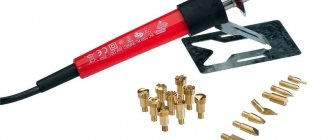
Stone repair kit
This set is used to repair damage to the surface of artificial stone products. The set contains 2 elements. One makes the cork, and the second makes a hole for it.
You can also use cutters from CERATIZIT for processing composites.
These are diamond cutters that are distinguished by their wear resistance. They are made by sintering several layers of diamond chips. The multi-layer coating allows you to extend the service life of the tool, since during its operation new layers of abrasive appear to replace worn-out layers.