For many projects, a CNC router is necessary for good and fast results. After some research on the current CNC machines, I came to the conclusion that all the machines under 150k could not meet my needs in terms of workspace and accuracy.
What I want:
- working space 900 x 400 x 120 mm
- relatively quiet spindle with high power at low rotation speeds
- maximum possible rigidity (for milling aluminum parts)
- highest possible accuracy
- USB interface
- spend up to 150 thousand rubles
With these requirements, I began 3D design by developing schematics and drawings, testing the many parts available. The main requirement: the parts must fit together. In the end I decided to build the machine on a 30-B nut with 8 aluminum frames with 16mm ball bearing spindles, 15mm ball bearing guides and 3 amp NEMA23 stepper motors that fit easily into the off the shelf mounting system.
These parts fit together perfectly without the need for special parts.
Models on the Internet
Current models for CNC can simply be found on the Internet by typing the appropriate phrase in Yandex or Google. At the same time, you don’t have to pay to download them; they are posted on various sites completely free of charge. It is worth taking a close look at the details of the site where the download is offered. There are a great many of them, but the files on some of them may be infected with a virus. It is recommended to download only if the site looks “real”. For example, there are no pop-up windows or annoying advertising. A good confirmation that the files on the site really contain the desired models are the comments of the downloaders, although they can also be falsified, you need to look at how humanly they are made. However, with due care, damage can be avoided. At the same time, free models will not necessarily be of good quality, so it is indicated that it is necessary to check how well they work before processing the workpieces in accordance with these drawings. Among the models presented on the sites, you can find various household items. In particular, one page lists such types of utensils as bread bins, cutting boards, shelves, as well as more complex items - clocks and lamps. On the other you can find models for chess pieces. On the third there are ornaments for wooden furniture, and, in addition, frames, brackets, and moldings. All models are presented in the form of a slide show right there on the page, so you can view them. Download links lead to an easy-to-use file hosting service called Yandex.Disk. As you can see, it is not difficult to find models for CNC in open sources on the Internet. If desired, any user will find products to his liking and 3D mill them on his own machine. At the same time, many strive to create something of their own. For such owners of CNC machines, the opportunity to create their own models is open.
Assembly
At this stage there are a minimum of subtleties:
- PVA glue is applied to the surface of the parts to be joined with a cotton swab or brush (depending on the gluing area), after which the parts are aligned and pressed against each other with the maximum force safe for their integrity. It is advisable to fix them under pressure until the glue dries completely (about a day);
- You need to use epoxy glue in the same way. Pay special attention to thoroughly mixing it with the hardener and the ratio of hardener to resin. In general, it is better to add a little more than the recommended amount of hardener: this will make the resin polymerize faster.
It is better to remove traces of squeezed out glue from the surface of the parts immediately: after it dries, it will be immeasurably more difficult to make the surrounding area of the seam smooth.
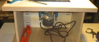
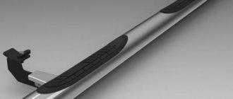
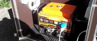
The photo shows the assembled machine.
Application area
Milling machines are used for complex machining of parts in three coordinates. Among the simplest types of milling: the process of engraving and cutting parts from sheet materials. Feedstock: plywood, textolite, plastic. The result is flat parts, which are later assembled into some kind of structure. These can be boxes, caskets, electrical equipment housings, frames of volumetric products. Two-dimensional processing is also used to create artistic products.
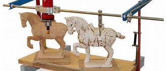
A more complex type of processing is volumetric or three-dimensional. It allows you to cut products with complex surfaces from massive blanks. For example, machine-made wood carvings are often superior to hand-made ones. Installing an additional rotary axis on the machine further expands its capabilities. Four-axis turning allows you to produce cylindrical parts or three-dimensional products with highly complex relief. Examples include sculptures or curved furniture fronts. It is possible to create machines with an even greater number of degrees of freedom, but today this remains the domain of professionals.
In addition to classic milling, a CNC router can be used to perform other types of work. Instead of a milling head, plotter knives, lasers or 3D printer extruders can be easily mounted. In some cases, plasmatrons are installed for cutting metal. All these tools do not change the equipment design and control methods.
Mistakes and ways to avoid them
The most common mistakes:
- Rotary axis play. If there is backlash, very often steps will appear on the workpiece. It is necessary to install the bearing as tightly as possible. It should be pressed into the guide with difficulty.
- The fourth axis must be located strictly perpendicular to the X axis. Otherwise, the parts will be processed with a slope in one direction.
- It is necessary to use a high-quality stepper motor. This is the key to accuracy of work.
A rotary axis for CNC machines is often a necessary element. Without it, it will not be possible to process complex parts in large quantities. It simplifies and speeds up work.
- November 08, 2020
- 4826
Peculiarities
Rotary axes are not installed on all types of machines. The main task of this element is to ensure rotation of the workpiece around its axis. Using the device, you can process parts made from the following materials:
- tree;
- plastic;
- aluminum, copper and other non-ferrous metals.
Rotation is carried out using a motor. The rotary axis can be part of the machine or installed separately. If the installation is carried out separately, then the element in this case acts as the fourth axis.
Four-axis machining has certain advantages over three-axis machining. The three-axis method makes it possible to do 3D processing of a part only on one side, since the other is fixed on the table. To process the other side, the workpiece must be reinstalled. The rotary axis completely solves this problem. Thanks to it, you can work with the part from all sides without additional actions.
This makes it possible to obtain products of complex shapes. Therefore, the fourth axis is necessary during manufacturing:
- jewelry;
- furniture components;
- various decorative inserts;
- souvenirs, such as chess pieces.
CNC machines with a rotary axis are widely used in the manufacture of decorative elements. When configured correctly, the equipment operates almost autonomously.
How to cut parts for a CNC machine from plywood?
All elements not included in the list above must be made of plywood. Therefore, the question of competent processing comes first when making a machine from plywood.
How to properly cut a plywood sheet?
In the process of cutting a sheet of plywood, you need to adhere to some rules:
- For material whose thickness is ten millimeters, manual and electric jigsaws are used, in which the blade has small teeth.
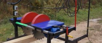
- Plywood larger than ten millimeters is cut with a circular saw.
- The material to be cut must be dried, otherwise it will delaminate.
- The sheet should be cut near the fibers of the first layer.
- If an electric tool is used, the feed should be at a minimum.
- To prevent chipping, you can use paper tape.
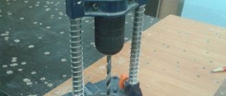
How to make holes correctly?
To make holes in plywood elements, it is better to use a drilling machine. In this case, you need to choose a high drill speed and minimum feed. A milling and engraving machine can also be used, which will allow you to make holes of any shape.
Help: If there is no such device, then a simple drill will do. The only thing that is needed is that the runout of the cartridge be minimal. Otherwise, the error will become higher.
How to sand and process?
After the process of sawing and drilling holes, the workpiece should be sanded. To do this, use sandpaper. Sanding is carried out near the fibers and starts from the corner, which is sanded at the very end.
Information: after the grinding process, the entire surface of the part is coated with special compounds that prevent unraveling and cracking.
Self-assembly of the frame of a desktop CNC machine 2418 or Our hands are not for boredom, part two
I continue the previous review on the topic of building a CNC2418 machine from an aluminum profile with my own hands. There will be brief instructions for assembling the frame and an approximate cost calculation. I promised - I continue. There is a lot of material, I try to prepare and publish everything in a short time. Last time I described the components for assembling desktop CNC machines like the CNC1610 or CNC2418. Part one: components
Part Two: Frame Assembly Part Three: Y-Axis and Work Table Assembly Part Four: Machine Electronics
Appearance of the popular CNC2418 machine
And a few words about the CNC2418 machine
As a rule, it sells for around $250 (from $170 to $300) in different configurations. There is a version with different spindles (different variations of the 775 motor), with different collets (from simple for drills to ER11), and can be equipped with a laser module. Usually sellers include consumables, cutter bits, etc.
Characteristics of the machine 2418:
- Working field - 240 mm x 180 mm x45 mm
- Frame size (bed) - 260 mm x 180 mm (aluminum profile)
- Overall size - 330x340x240
- Stepper motors: 3pcs Nema17 1.3A 0.25Nm
- Spindle: Diameter 45mm, model 775, 24V: 7000 r/min
- The maximum diameter of the cutter shank depends on the installed collet
- Power: 24V 5.6A
Electronics such as Atmega+CNC Shield, EleckMill, or original boards, but with GRBL firmware.
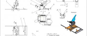
They are controlled using GrblController, UniversalGcodeSender, grblControl, and use *.nc files. Such files need to be generated separately. Frame dimensions and axle locations CNC 2418
Collet Options
The original 2418 machine (as well as the similar 1610) contains 3D printed components.
The use of such plastic parts is clearly visible in user photographs from the Internet, and in lots from sellers
The printed set includes an angle spacer (2 pcs), a screw holder X, a screw holder Y, bearing holders LM8UU (or rather their imitation) 4 pcs, a nut holder T8.
I will separately highlight the spindle holder assembly and at the same time the XY carriage. It comes complete with the engine installed.
Model of a similar spindle mount
Now a little more detail about the main assembly.
So, to assemble the frame you will need the following components:
- Profile sections 2022 (two longitudinal, 5 transverse, 2 vertical parts)
- Corners for profile 16 pcs
- T-nuts M3 or M4 for groove - 6mm
- Screws for installation with T-nuts (M3 or M4, respectively, 8…10 mm, plus M3x12 for mounting motors)
- Spacer (45° angle)
- Tool (screwdriver)
Since I started talking about the profile, just in case I’ll repeat about the purchase and cutting of the profile from Soberizavod.
This is a structural aluminum profile from Soberizavod. I immediately bought a profile kit cut to size for 2418. There are two options - an uncoated profile (cheaper) and a coated (anodized) one. The difference in cost is small, I recommend coated, especially if used as guides for rollers.
Select the desired profile type 2022, then enter “cut to size.” Otherwise, you can buy one piece (whip) per 4 meters. When calculating, keep in mind that the cost of one cut varies depending on the profile. And that 4 mm is allowed for the cut.
Enter the sizes of the segments. I made the 2418 machine a little larger, these are seven sections of 260 mm and two vertical sections of 300 mm. The vertical one can be made smaller. If you need a longer machine, then two longitudinal sections are larger, for example, 350 mm, and transverse sections are also 260 mm (5 pieces).
Confirm (must be added to the cutting map) Check the cart
The profile is obtained for 667 rubles together with the cutting service.
Delivery is carried out by TK, you can calculate the cost using a calculator, since you know the profile dimensions, the weight is very well calculated in the cutting chart. For the calculation, you need the option “cargo pickup from the supplier.” Delivery via Business lines will cost less, about 1000 rubles. You can pick it up in Moscow.
In one place there is an office, a warehouse and a workshop where profiles are cut to size. There is a showcase with samples, you can select a profile on the spot.
So, let's start assembling the frame of the tabletop machine 2418. Here is the already cut profile.
In this design, I increased the Z axis (a little more by a couple of cm than the others) in order to use the machine as a CNC drill. In the original, the Z axis is the shortest. You already decide this according to your goals. To extend the working field, you need to buy two sections of the profile (longitudinal pair) larger by the required length (for example, +10 cm), the guides are lengthened accordingly (+10 cm for a pair of 8mm shafts) and the screw (+10 cm for a T8 screw). In terms of money, the stated +10 cm comes out very cheap: the cost of a 10+10 cm profile is about 40 rubles, the guides and screw will cost plus $6 (check).
Here are the corners prepared for assembly
This is how the T-nuts should be installed in the slot. You can not thread it from the end, but install it directly into the groove of the profile sideways, but then control the rotation and installation of the nut, since this does not always happen, some skill is required.
The profile cut is clean, there are no burrs
The profile is twenty, that is, from the 2022 series, with corresponding dimensions of 20 mm x 20 mm, a groove of 6 mm.
So, first we assemble the U-shaped part of the frame, attach two longitudinal parts of the profile and one outer cross member. It doesn’t really matter which side you assemble from, but keep in mind that there is a central crossbar that is moved closer to the back. It is part of the vertical plane, and the size of the offset depends on the offset of the Z axis and the spindle. Place it so that the spindle rotation axis is in the center of the machine (Y axis). Next we assemble the middle cross member. It is more convenient to first install both corners on a section of the profile and fix them, and then install them to the frame. We apply a section of the profile, measure the same distance with a ruler, and tighten the screws. The screws must be tightened slowly, allowing time for the T-nut to turn and take its position in the groove. If it doesn't work the first time, loosen the nut again and repeat. We install the last part of the horizontal frame. It's easier to access with a long screwdriver. Don’t be lazy and check the right angles of the resulting structure with a square and the diagonals with a ruler.
Since the corners of the structure are directed towards each other, it does not matter in what order they are assembled. I did the same as in the basic CNC2418 design. But intuition suggests that it makes sense to increase the distance between the profiles, especially with a higher portal height. Okay, that can be done later.
Next we begin to assemble the vertical portal mount
We install the assembled portal on the horizontal part, fasten it with 6 corners (installed in three directions from the vertical profile).
We establish and maintain the perpendicularity of the segments (along the square). Then I tightened all the screws one by one.
: It turned out that the original was 3D printed too. If anything, you can replace it with perforated fasteners from stores, or furniture corners. This will not affect the quality in any way.
At first glance, the structure turned out to be solid, not shaky. It can be seen that the plate with the engine is shorter than the KP08+SK8 caliper set. I'll spread it wider.
In fact, this frame is a copy of a similar design of the CNC2418 machine, except that I didn’t directly copy the dimensions, I made it a little larger in order to have less scraps from guides and screws.
The frame assembly is complete, now you can start installing the engines. I use 3D printed flanges to mount the motors. It is advisable to make the upper ones assembled with guide holders, the lower ones - without holders, since the Y axis should be wider. It is advisable to install the Y axis on supports SK8 and KP08, as in the original machine. The calipers themselves can be printed on a printer or purchased (links are at the end of the topic, and were also in the first post).
For one of the axes (the X and Y axes are the same length), I took a “sighting” kit with a Nema17 engine plus a propeller and calipers. I didn’t yet know my “wants” for the size of the machine. As a result, the scraps from the screw will go to the Z axis; you will only need to purchase a T8 brass nut.
It was packed in a cardboard box, inside each part was in a bag separately.
The kit looks like this: a motor with a short wire, a T8 lead screw, two KP08 calipers and two 5x8 couplings. There is a similar kit for 400 mm and 300 mm, as well as without an engine for 600 mm (with calipers and nut). If you take without a large margin, then the 400 mm option will work well for the “enlarged version” of the machine
Additional information - photos of the kit separately
Engine marking RB Step Motor 42SHDC3025-24B-500, seat Nema17
A short wire for connection is included. Conveniently, you can simply increase the length without touching the connectors.
T8 screw, nut
KR08 calipers. Convenient to attach to the profile. If you use a wide flange for installation, then it is better to use the KFL08 version of the caliper; it allows you to attach the screw not to the profile, but to the flange. 5x8 coupling is a split coupling for connecting the motor shaft to the propeller.
This is how the engine is originally mounted on the X-axis. On a small aluminum plate.
I did the same thing, only with a printing plate. At the same time it will be a support for the guides.
I have already cut off the extra length of the screw for the Z axis (the Z axis is still in process, the information will be separately, most likely also 3D printed).
Most likely, you will need to lengthen the motor wires in order to carefully route it along the profile to the upper part to the electronics board (most likely there will be a CNC Shield). And it wouldn’t hurt to install limit switches for extreme positions. The basic information on the assembly is already there, you can start estimating costs))))
Costing
Now, as requested in the comments in the first part, I propose to discuss costing.
Naturally, I spent less than indicated, since I had the engines and most of the components in stock. much cheaper
if you use homemade printed corners for the profile, supports, flanges, and so on.
This is unlikely to affect the operation of the machine for drilling printed circuit boards and milling soft materials. Another good option is to use perforated plates from construction/hardware stores. Suitable for strengthening corners, including vertical ones, and for installing an engine, provided the central part is drilled for the shaft. Instead of perforated fasteners, you can use homemade ones made from aluminum sheet or plywood. You definitely need to purchase the 2020 profile
, otherwise it will be a completely different type of machine.
You can do the same thing from an aluminum corner or a rectangular pipe, but only for the love of art))) There are more optimal designs in terms of rigidity for assembly from a corner/pipe. The profile definitely needs T-nuts
.
You can buy T-bolts, but T-nuts are more universal (since any screw length can be used). But the rest can be changed at your discretion; you can even
use
stainless steel
pin a T8 lead screw Unless the number of steps per mm will have to be recalculated in the firmware. Motors
can be removed from old devices/office equipment and seats can be planned for a specific type.
electronics
(Anduino UNO/Anduino Nano, CNCShield, Mega R3+Ramps, A4988/DRV8825 drivers, you can use an adapter board for Mach3 and TB6600 drivers. But the choice of electronics is limited by the software used. For drilling, you can use any
DC motor allows you to install a collet chuck and has a decent speed.The basic version has a high-speed motor 775. For milling, you can use 300-watt non-slip spindles with an ER11 collet, but this greatly increases the cost of the machine as a whole.
Approximate cost calculation: Soberizavod 2022 profile (2.5 meters) = 667 RUR Soberizavod 2080 profile (0.5 meters) for desktop = 485 RUR Two sets for 300 mm axles 2x$25 Corners for profile 16 pcs. A lot of 20 pieces comes out to $5.5 with delivery of T-nuts about 4 rubles per piece if you take a large package. You need at least 50 pieces (mounting engines, calipers). I don’t count the screws for them, usually a few kopecks per piece depending on the quality. Total about 400...500 rub. Nema17 motors 3 pieces $8.25 each Electronics CNC Shield board $2 Arduino Uno $3.5 A4988 three pieces $1
The machine comes out to about $111. If you add the spindle: Motor 775 $9 Chuck ER11 $7.78, then the total cost is about $128
I do not evaluate 3D printed parts. Can be replaced with perforated plates/corners from crepe markets and similar stores. I also don’t estimate the wires, electrical tape, or time spent. Let me remind you that not all CNC2418 configuration options have such good 775 engines and, especially, an ER11 collet.
Cheaper options
: Shaft 8x600, a couple of pieces and sawed in half. For the Z-axis, take a short 8x300 Instead of SC8UU, use LM8UU Calipers SK8, KP08, T8 nut holders, LM8UU bearing holders, corners for the profile - 3D printed.
You can get guides of a longer length than in China, for example, in the Duxe.ru store. As an option, you can buy polished Shaft SFC-8/600 and SFC-8/1000. The issue price is 250 rubles and 410 rubles, respectively (plus delivery). This will make three pairs of guides with a large margin.
Assembly instructions for the original 2418
3D printed parts, for savings:
Entire CNC project with printed parts. I recommend using the XY carriage model from here Mounting model for the spindle Similar clamp from CNC3020 Good fastening of the pair LM8UU Simple holder LM8UU and another Bearings lm8uu can also be printed from PLA Nema 17 motor mount - motor mount 8 mm support with bearing SK8 mount SHF8 Reinforced corner for the profile A few more details, including flanges and a 45° angle
Thank you for your attention. Next will be about the assembly of XY axes and electronics
Management
This guide aims to prevent you from making the same mistakes that I wasted my precious time and money on.
We'll look at all the components down to the bolts, looking at the advantages and disadvantages of each type of each part. I will talk about every aspect of design and show you how to create a CNC milling machine with your own hands. I'll take you through the mechanics to the software and everything in between.
Keep in mind that homemade CNC machine plans offer few solutions to some problems. This often results in sloppy design or poor machine performance. That's why I suggest you read this guide first.
LET'S START
STEP 1: Key design decisions
First of all, the following questions need to be considered:
- Determining a suitable design specifically for you (for example, if you make a woodworking machine with your own hands).
- Required processing area.
- Availability of work space.
- Materials.
- Tolerances.
- Design methods.
- Available tools.
- Budget.
STEP 2: Base and X-Axis
The following questions are addressed here:
- Design and build the main base or X-axis base.
- Breakdown of various structures into elements.
- Rigidly fixed parts.
- Partially fixed parts, etc.
STEP 3: Design the Gantry Y Axis
This paragraph addresses the following issues:
- Design and construction of the portal Y axis.
- Breakdown of various structures into elements.
- Forces and moments on the portal, etc.
Sawing parts
How and with what can you cut plywood machine parts? If the thickness is 4 mm, you will have to cut it out yourself, using a hand jigsaw with a tension saw. Using a tool with a significant tooth size is guaranteed to decorate the edges of the workpieces with raised wood chips.
Tip: sticking tape over the workpiece will help reduce the number of scuffs.
Material with a thickness of 6 millimeters or more can be sawed with a jigsaw or (for a simple part shape with a predominance of straight lines) with a hand-held circular saw.
As in any other business, there are some subtleties here:
- A jigsaw uses a metal file with a minimum tooth size. They make the chances of picking up chips around the edges minimal;
- Both the saw and the wood jigsaw are guided along the cutting line at minimum speed. The higher the tool speed, the rougher the cut edges.
Read also: Stove gas burners with automatic
It is advisable to cut small parts with a small (0.5-1 mm) margin in size and finish them with a file, this way there is less chance of missing the size. It is necessary to process the edges with a file, holding the part in a vice (wooden or metal with plywood spacers) at the level of the cutting line.
The finished part is ground not only along the edge, but also along the plane.
Particular attention should be paid to the surface of the desktop.
How to make a homemade fourth axis for a CNC machine with your own hands: step-by-step instructions
Making a rotary axis with your own hands is not very difficult. The main thing is to follow the instructions provided.
Materials and tools
To make the fourth axis you will need to prepare the following:
- plywood 15 mm thick;
- bolts 60–70 mm long and nuts for them;
- water pump bearing from VAZ;
- varnish or paint;
- gears with 60 and 12 teeth;
- Belting;
- stepper motor;
- drill or drilling machine;
- set of taps;
- two clamping parts (you will have to order them from a turner);
- stepper motor control driver;
Manufacturing process
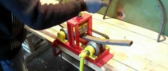
First, a drawing of the guides is made using the Rhinoceros program. They will be made of plywood. This is shown in the picture below.
After this, plywood is fixed to the CNC machine and 8 such parts are cut out. 4 pieces are fastened with bolts. After this, they can be painted or varnished.
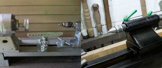
A water pump bearing is pressed into one of the resulting parts. The table is removed from the machine, and the plywood guides are installed in their place.
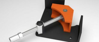
The parts ordered from the turner (see picture) are mounted on the guides.
A large gear is installed on the bearing on the rear side, and a small one is placed on the stepper motor. They need to be connected with a belt.
The stepper motor control driver is installed in the machine control unit. After this, you can proceed to setting up the fourth axis.
Setting up a homemade 4th axis
Programming a rotary axis is usually not particularly difficult. The main thing is to take into account several important points:
- The fourth axis is capable of rotating in both directions: forward and reverse. The corresponding sign and side must be determined based on the right hand rule.
- Rotation can be programmed both in relative and absolute coordinates.
- Most stepper motors have a limit on the rotation angle. For example, if you need to rotate a part 400 degrees, but you can only program 360, then you need to make an additional frame with an angle of 40 degrees relative to the previous position of the part.
It should also be taken into account that the further you move away from the center of rotation, the more the linear movement error will increase.