Making a lathe
homemade turning and copying machine
The most primitive model of a lathe is made from an ordinary drill. But this is not the only solution. Main parts of the future device:
- bed;
- front and rear pillars (headstocks);
- electric motor;
- master and slave centers;
- tool rest.
The bed is the base for placing all elements and mechanisms. Therefore, it is made of thick timber or metal. The headstock is securely fixed to the base; the part will be attached to it. The front pillar houses a device that transmits movement from the electric motor to the driving center and then to the part.
The rear post (headstock) moves along a guide on the bed; it holds the free end of the workpiece. A tool rest is placed between the headstocks. The headstocks must be positioned strictly along a single axis.
For a do-it-yourself machine, an electric motor with a power of 200 - 250 W, with a speed of no more than 1500, is suitable. If you plan to process large parts, a more powerful motor is required.
A faceplate is placed on the electric motor pulley, which secures large workpieces. The faceplate contains points on which the part is pressed. The opposite end of the part is fixed with a corner.
To turn a regular lathe into a copying machine, an additional device is required - a copier.
Making a machine with your own hands
There are a huge number of copy-type woodworking machines, which are known as pantographs, and have a CNC system (a universal option that allows processing using a copier or program). However, not everyone can purchase such equipment, which is associated with its very high cost. The addition of CNC makes the equipment available only to large manufacturers, when the payback period for the equipment will be less than 5 years. That is why many people ask the question - how to make a machine with your own hands?
Before you start work, it is worth remembering that do-it-yourself machines are significantly inferior to industrial models. At the same time, it is impossible to make a CNC version yourself. Also, many note that converting a regular milling version into a copying version with your own hands is also very difficult, and, often, it is easier to start from scratch. It is not difficult to make a pantograph yourself, but there are still certain difficulties in this process.
Homemade pantograph for a router
There are many schemes by which you can create a copy-milling machine with your own hands. A typical version usually consists of the following elements:
- Desktop;
- supporting frame;
- milling head.
To carry out the procedure for changing the cutting mode, the height of the table changes; the head with the cutter has an electric drive, which sets the cutting tool in motion; often the system includes a transmission mechanism for changing speeds.
The pantograph itself can be made as follows:
- Made of wood. You can create such a pantograph with your own hands, but it will have low processing accuracy, since the wooden parts are connected using a loop. Fastening with loops is characterized by backlash.
- Drawing pantograph made of metal - allows you to create copies at various scales, but cannot be used to create three-dimensional copies.
When creating a machine with your own hands, you should take into account that many parts may have flaws and discrepancies in size. This situation is associated with vibration and trembling of the base, which is quite difficult to avoid. When changing the direction of movement of the cutter, errors are also possible. Due to the internal stress of the wood workpiece, the workpiece may become distorted. Therefore, it is recommended to create such equipment only for narrow-profile production, when the machine will be designed to create one part. It is almost impossible to avoid the problems under consideration, however, provided that the same part is processed, gradual improvement of the design is possible.
Personal assembly of equipment at home
Lathe
In order to assemble a small copying machine for wood with your own hands, you will need to make some effort and patience, as well as invest financially (about 7-7.5 thousand rubles). But this is several times less than the costs that await you if you purchase a ready-made option.
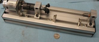
These are the masterpieces of interaction between hands and head found in private workshops
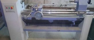
The model of small-sized equipment of the so-called beam type proposed for assembly can be divided into the following components:
- Frame.
- Slave and leading center.
- Electric motor.
- Front and rear headstock.
- Stop for cutter.
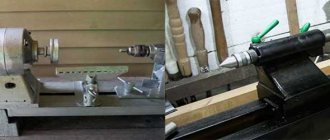
Now we’ll tell you in more detail about how a wood copying lathe looks and is assembled:
It is clear that the frame is the foundation of the entire structure, on which all other parts will be based. Therefore, appropriate requirements are placed on it. It must be strong, stable and reliable. Therefore, it is better to make it from a steel profile, but a wooden beam with a large cross-section is also quite suitable. The electric motor and the driving center are connected to each other and fixed to the front of the base. Due to the electric drive, the blank is rotated.
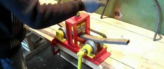
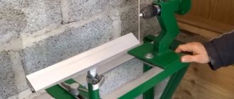
Another option where the sampling depth depends on physical strength (pressing the handle, in the photo)
- The headstock serves as a stop for the workpiece, so it is permanently attached to the frame.
- By moving the tailstock along the frame, the workpiece will be transformed into a part of a given sample.
- A stop for the cutter is installed between the tailstock and the front headstock, which will serve as a holder.
- The tailstock and front headstock and the stop for the cutter are mounted clearly along one line.
- All components of the machine must be securely fastened with bolts.
Fasteners should be chosen only new, galvanized, tightening all individual elements with force so that the connection does not come loose. And wood turning and copying machines should be installed only level to avoid the slightest vibration.
Milling machine
If you wish, you can also assemble a homemade copy milling machine for wood with your own hands.
Such a device is capable of:
- Planar milling for creating profiles.
- Volumetric milling for the design of reliefs.
A copying cutter for wood made of carbide metal reproduces the surface or contour of the master copier on the product.
The following is used as a copier:
- Spatial model.
- Flat template.
- Reference model.
- Outline drawing.
The simplest milling copier consists of a supporting frame - a base, a work table and directly a milling head equipped with an electric drive.
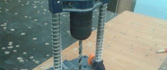
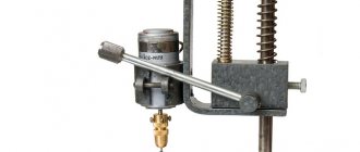
A hole is made in the center of the board and a router is attached in place of the hole, only on the reverse side
- The dimensions of the workbench depend on the specific tasks for which the copy milling machine is assembled, as well as on the dimensions of the workroom.
- Based on the nature of the work and the dimensions of future products, methods for fastening the workpieces and template are determined.
- The power of the electric motor that rotates the cutter is also selected taking into account the planned loads.
Thus, having a copy-milling machine for wood in your workshop, you can create copies of the parts necessary for repairing furniture and other wooden structures with your own hands. You can also make souvenir or decorative items according to your own drawings.
Since work on such equipment is quite dusty, it is best to place the machine outside or under a hood
Disadvantages of the device in question
Along with numerous advantages, the copier has minor disadvantages. Among them:
- The working surface is guided by hand, because during operation it can jam or warp.
- It is possible to copy simple details.
- To move the tool, it is recommended to choose a helical gear type.
- For universal qualities, it is recommended to replace the cutter with a circular saw.
Thus, to copy complex parts, it is better to install industrial types of equipment. Homemade options are suitable for workshops.
Classic machine design
The machines are equipped with a sophisticated design system. These include CNC models that operate in an automated mode. Such devices are obtained by using drawings and a copying device. The classic design consists of five nodes:
- The main element is a metal frame; individual parts are connected by welding. The bed has different heights, so when creating a homemade machine, this particular parameter is selected.
- The front and tailstock are needed to store the box, drive and electric motor. The rear one fixes the workpiece to obtain dimensional parts.
- An electric motor and drive rotate the workpiece.
- A tool rest is needed for the best quality work. The cut site is protected to prevent injury.
- The master and slave centers secure the part.
Homemade wood turning and copying machine with your own hands
Industrial types of copiers are not cheap, so craftsmen choose the option of constructing a homemade machine. It requires little investment of money and effort.
Performance generally depends on the specifications of the copier. The main task of a self-made device is to create parts according to a template without additional energy consumption.
Required Tools
You won’t need many tools; all of them are publicly available and available to every master:
- Manual frezer.
- The cutter is placed on a support, which can be made of plywood 12 mm thick. Metal is used to improve performance. The dimensions of the platform are about 50x20 cm.
- Bolts.
- Thrust bars.
- A pipe with a diameter of 25 mm will allow you to set the direction of movement of the support platform.
The fundamental cutting tool when constructing a lathe with a copier is considered to be a hand cutter. Even though the copier is made of plywood, it is capable of creating many copies.
Design elements
The simplest and most affordable model of the unit is made from a standard drill. Main equipment spare parts:
- Bed.
- Front, rear grandma.
- Electrical engine.
- Leading, driven center.
- Support for equipment.
All processing components are located on the bed. It can be wooden or metal. The headstock is placed on the platform, and the part is fixed to it. There is a device in front that controls the rotation from the engine to the drive shaft to the part.
The rear post moves along the directional axis; it serves to hold the edge of the profile. Between the headstocks there is a stop for equipment. The products must be on the same plane.
Manufacturing stages
If you need to turn a lathe into a copy machine, you will need an additional device - a copier. Stages of machine assembly:
- You should come up with or download a drawing, which will later be used for assembly. Usually this is a diagram of a standard device that adapts to the copier.
- The process begins with the bed, which requires angles and metal sheets. They are connected by welding. Must meet the requirements of reliability and vibration resistance.
- For maximum functionality of the equipment, an electric motor is installed, designed for 200-250 W, picking up about 1500 rpm. For processing large-sized profiles, it is recommended to choose a higher power motor.
- A faceplate is fixed to the shaft. It is equipped with sharp ends that transmit rotational force.
Particular attention is paid to the manufacture of the copier. It is the main difference between a lathe and a copying machine.
How to make a copier for a lathe?
The copier is indispensable in the production of identical parts. Thanks to it, productivity increases. Some aspects of the copier layout include:
- The main unit is a manual milling cutter that is superfluous in the workshop.
- To install it, a plywood surface is required.
- Holes are made and bars are placed for fastening.
- The bars are fastened with self-tapping screws, which securely fix the devices.
- To cut the workpiece, the platform must move easily along the bed.
- When creating a copier, it is necessary to have a level, because any deviation leads to an error.
- The block is placed horizontally. There is a template for it. The beam is fixed with self-tapping screws.
- The design must be created so that, if desired, the copier can be folded out and the device can be used as standard equipment.
The template is made from plywood and screwed to the front of the beam. The upper platform is checked to ensure it matches the axis on the template.
Installation of structural elements
In order for the copying machine to carry out the most efficient work, and the procedure to be of high quality, rush is eliminated. After studying the drawing, you must adhere to the specified parameters.
It is recommended to pay attention to a few tips:
- The axis for tool movement is set parallel to the axis of the workpiece.
- The coincidence of pipe lines and equipment is an important plus.
- It is important that the bottom edge of the router is aligned with the axis of the equipment. This may vary depending on the installation level of the copier.
- It is better to fix the guide pipe with wooden boards through blind holes.
- The bars of the supporting surface should move and slide easily. If they wobble, the structure will have to be rebuilt.
Some masters are concerned about the moment when high requirements regarding sliding are provided. It’s easy to design a machine with excellent options; just select a straight pipe with smooth walls.
How to make a wood lathe: making a bed
In serial devices, the frame is in most cases made of cast iron. This material is distinguished by its mass. For a homemade unit, you should choose a less heavy option. For example, as the basis for a future design, you can choose angles made of rolled angle steel. The recommended length of the segments is 125 cm.
The length of the bed can be increased, but this action will require intervention in other parts of the woodworking unit. Before making it, it is recommended to draw up a plan on paper. You can also take a ready-made drawing from the specialized website that will help you assemble a wood lathe with your own hands.
Let us consider step by step the algorithm of actions for the manufacture of this unit. First of all, you need to place the corresponding corners on a horizontal surface (open side to each other). Then it is recommended to place calibrated inserts between them, which will allow you to maintain the required distance of 4.5 cm.
The components of a homemade lathe are placed directly on the bed
Next you need to connect the guides. For these purposes, the same corners are most often used, differing only in size (19 cm). It is recommended to mark the points at which welding will be performed in advance. The jumpers are located near the edges of the long corners. The next step is the welding itself.
Helpful information! The bed of any homemade woodworking machine is the basis of the structure, so its installation is very important. Any violation in the future will affect the efficiency and accuracy of the unit, made by hand.
Then you need to attach another jumper of the same size. It should have cutouts for long corners. After installing this part, a cell should be formed for the headstock tenon. The dimensions of this geometric element require precise adherence. To install a standard headstock tenon, 4.5 x 16.5 cm is sufficient.
Do-it-yourself woodworking machine: how to make a tool rest
Traditionally, this part includes two components. They are made from steel corners. The standard dimensions of workpieces for welding are 5 and 3 cm. The joining of these elements is carried out by welding (in length). The result is two segments, which should have a length of 26 and 60 cm.
Tool rest on a lathe - needed to support the cutters when working with wood
The short element is used as a customizable support base. Moreover, one of the corner shelves must be cut at an angle so that 11 cm of the untouched profile remains. Before performing the same manipulation on the other wing, it is necessary to step back from the edge by 6 cm. The angle itself in the second case remains straight.
Next, you need to make a counter frame for a homemade woodworking machine. A steel plate is suitable for the manufacture of this element. The next step is to make the guide element and its clamp. As a material for these purposes, you can use a regular inch pipe. You need to make a longitudinal slot in it using a grinder. Craftsmen advise not to make this part longer than 15 cm.
Then the guide sleeve is installed in a 2.5 cm corner. The cut made with a grinder should be perpendicular to one of the shelves. Next, the structure must be fixed in a clamp and connected using welding equipment. After this, the tube is covered with a second corner and connected to it in the same way.
The finished guide part is joined by welding to the protruding flange of the angle. For final fastening, it is necessary to weld a nut to the rail, and equip the second part with a screw. Also, do not forget that on the reverse side you need to perform additional fixation of the structure. To do this, you can weld a metal rod to its individual parts. It will give the structure strength and rigidity.
Diagram of a tool rest for a lathe on an eccentric clamp
The tool rest is fixed on a piece of reinforcement (smooth), which should have a diameter of 2 cm. Such a rod is fixed on the back side of the corner approximately in its center. At the end, it is necessary to connect the reinforcement to a long part (60 cm).
Homemade wood lathe: choosing a drive
The drive must have sufficient power to process wood products. When purchasing this device, it is advisable to pay attention to the standard models. Their power varies from 1200 to 2000 watts. This is quite enough for processing various kinds of parts at home. The most commonly used drive is a power rating of 1200 watts.
Induction motors are often used in homemade wood lathes. It is not possible to make this device with your own hands. Another characteristic that is common among drives installed on self-made machines is three-phase operation.
Note! When assembling such equipment at home, it is quite difficult to purchase an engine that would have the required rotation speed. However, if desired, this indicator can be adjusted by changing the diameter of the pulleys.
A homemade lathe must have sufficient power to process wood products
When installing the drive, it is recommended to equip the frame with a special plate. It is fixed on the gate canopies and ensures a tighter pressing of the strap. Some craftsmen install a pedal on the platform, which allows them to change the number of revolutions per second while processing a wooden block.
DIY lathe: headstock and tailstock
To manufacture these components, you must have access to a metalworking machine. If this is not possible, it is recommended to purchase ready-made structural elements. The headstock of a woodworking unit includes two housings that belong to the bearing category.
When assembling the machine yourself, it is important to remember that the height of the spindle axis above the base must be no less than 12 cm. This indicator affects the size of the front unit. The most suitable in this situation is a bearing block with a height of 7 cm. The shaft itself can be made on a metalworking device. Its diameter should not be less than 4 cm.
In turn, the procedure for making the tailstock of a wood lathe with your own hands is less complicated. This module includes 4 elements, including:
- base;
The headstock is designed to accurately support and move the part processed on the machine relative to the cutting tool or surface
- guide (external);
- inner tube;
- drive screw.
It is recommended to make the base from a steel angle, the height of which should not exceed 10 cm. To create a guide, you can use a tube measuring 4x15 cm. In its rear part, you must install a special plug with a hole (0.8 cm). In this case, the inner tube will have dimensions of 2 cm. Next, you need to make a drive screw. A thread is applied to it for the nut in the inner tube.
It is also worth noting that the headstock and tailstock should be on the same line. Otherwise, further construction of a woodworking machine will not bring any results. The headstocks are fixed to the bed in the same way as the tool rest.
Making cutters for a wood lathe with your own hands
If necessary, these functional elements can be purchased at a specialized store or ordered online. However, many craftsmen prefer to make these devices themselves. The most popular cutting elements today are Reyer and Meisel. They are quite simple to perform on a sharpening machine.
Turning cutters: A - with a semicircular blade for rough turning; B - with a straight blade for finishing turning; B - shaped; G - machine passage
In order to make these cutting elements, you will need a blank. You can use old tools (for example, a file) as it. The metalworking unit allows you to sharpen this blank quite quickly. Forming is performed at two points: where the blade will be located and the tail.
Related article:
Wood lathe: device, characteristics and review of models
Review of popular models of woodworking machines. Tips for selection and rules of use.
The next step in making a wood cutter with your own hands is stuffing a turned handle with a locking ring. In this way, you can independently produce cutters for a woodworking unit.
Note! As the initial material for making these functional elements, you can use not only files, but also rasps or fittings.
It is also important to remember that a homemade tool must first be tested on soft wood. Such a check will determine how well the cutter is made and whether it is advisable to use it when working with hard rocks.
Copier for lathe
guide pipe
The basis of the copier will be an unnecessary manual router. It is placed on a surface made of 12 mm plywood, the size of the platform is 20 x 50 cm. Holes are made in the platform for fasteners and cutters, and stops are installed - bars for fixing the cutter. The router is placed between the clamps and secured with a pair of large nails.
The remote part of the platform moves along the frame along a guide - a pipe. Its ends are fixed in wooden blocks. The bars are attached to the frame with self-tapping screws. When fixing the pipe, you must use a level and align the axis of the pipe with the center of the machine. Before installation, a pair of bars with holes are put on the pipe and can be easily moved along the guide. A platform on which the router is placed is attached to the bars.
stop-copier
The second important element is installed with your own hands directly on the lathe - a block in a horizontal position on which the templates will be attached. A 7 x 3 cm beam is suitable; it is attached to the vertical stands with self-tapping screws. The stands are screwed to the frame. The top surface of the block must clearly coincide with the axis of the machine.
When the copier is not in use, the block is dismantled, the platform with the milling cutter is moved back and the machine turns into a regular lathe.
The stop is made of thick plywood and is attached to the work surface. In fact, the stop plays the role of a copier in this design. It is fixed vertically and fixed to the end of the working surface on a transition beam made of wood. The copier can be removed, it is installed on the stand with self-tapping screws. The stand must be fixed firmly, without the possibility of removal.
The templates are made of plywood and are screwed to the front surface of the block using self-tapping screws. The upper surface of the beam should be aligned with the axis of the template.
Design and principle of operation of the machine
A lathe with a copier has the following device:
- Metal frame. It acts as a base to which the main components of turning equipment are attached. The individual elements are attached to the frame by welding.
- Front and rear pillars (headstocks). They house the drive, electric motor and gearbox. The front pillar is mounted on the platform. It houses a mechanism that ensures the transmission of torque from the power unit to the driving center and the workpiece. The tailstock (thrust) moves along the guide and holds the workpiece. The racks must be located on a single axis.
- Faceplate. It is attached to the electric motor pulley. The faceplate has points on which the workpiece is fixed.
- Spindle chuck. Used to hold the workpiece.
- Master and slave centers. They are used to secure a wooden product.
- Tool rest. It is designed to increase processing accuracy.
This type of turning equipment can also be equipped with additional devices:
- Milling attachment. It allows you to cut channels in a spiral shape in both directions and with different pitches.
- Lunette. It acts as a movable support and is used when working with long parts.
- Sanding attachment. This attachment is used for sanding hardwood products.
The following disadvantages of this design are highlighted:
- The working surface must be periodically moved manually. Otherwise it may jam or tilt.
- Using turning equipment, only simple workpieces can be processed.
- An additional helical gear is required to move the cutting tool.
The lathe has the following operating principle:
- The workpiece being processed is fixed to the spindle chuck.
- The workpiece is pressed by a persistent headstock.
- The electric motor turns on, transmitting torque through the drive to the spindle.
- The spindle transmits motion from the drive to the part.
- Cutters cut off unnecessary elements of the workpiece, giving it the required shape.
The edges of the workpiece inserted into the lathe must be folded. This is necessary so that the cutter fits tightly along the wooden surface.
Copier for lathe
The main element of the copier is a manual router. It is located on a platform made of wood materials with a thickness of 12 mm. Its size is 0.2×0.5 m. The platform contains holes for attaching the cutter and fasteners.
The router should be between the clamps. A separate part of the platform moves along a guide. Its ends are installed on wooden blocks.
Another important element of the copier is a block measuring 7x3 cm. It is fixed in a horizontal position. This element is attached to vertical stands. Templates made of plywood are installed on the block. It is important that the lathe has a thin stop. In this case, it will better copy the template.
If the copier is not used, the block can be dismantled. The platform where the router is located is retracted. To dismantle the copier, you need to unscrew the screws and other fasteners. In this case, the stand where the copier was installed must be tightly fixed.
How to choose the power of wood milling machine equipment for your home workshop
The manual router is designed specifically for work in small workshops or on the road. It is difficult to process large batches of lumber on it; such a machine simply cannot withstand the volume of work. Bulk workpieces are easier to process on stationary machines.
A comment
Andrey Feofanov
Tool selection specialist at VseInstruments.ru
Ask a Question
“To create complex designs on wood, you will have to purchase several types of cutters. Some of them can be made independently, others can be purchased in specialized stores.”
Low-power machines are quite suitable for home and household use. For example, 400 W is enough for small jobs and drilling in soft wood. Machines of this power can be used for cutting grooves. The price of manual wood routers is low, however, the range of functions is very limited.
If you plan to expand the specifics of processing, then it is better to opt for a model with a power of at least 1 kW
With such equipment you can easily work on any type of wood. This is quite enough for household needs. For professional use, it is recommended to choose a machine with a power of at least 1.5 kW. It is not always possible to buy such a wood milling machine, because the price can reach several tens of thousands of rubles. With such a machine it will be possible to process large volumes of wood, as well as plastics, soft alloys, such as aluminum; it will “eat” any type of cutter. Remember that the time it takes to complete a task depends on the power.
Spindle rotation speed is a very important characteristic that affects the price of a wood milling machine; you should pay attention to this parameter when choosing equipment. Processing dry or wet wood of varying densities is most effective at certain speeds
The dimensions of the working platform and the distance from the spindle axis to the worktop determine the dimensions of the workpieces being processed. The accuracy and depth of processing of the part, as well as the ability to select the desired cutter, depend on choosing the right spindle for a wood milling machine.
Dust extraction - when processing wood, an exhaust volute is an irreplaceable thing. Sometimes, for such purposes, ordinary vacuum cleaners are used, which are attached at a certain angle to the frame.
Dimensions and weight of the machine - for an amateur, a compact desktop model is suitable, which is installed on a workbench, and after use it is put away in the pantry. If you have a workshop, it is more advisable to assemble a full-fledged wood milling machine on a bed with your own hands. If you plan to work on a construction site, choose a manual router.
A comment
Andrey Feofanov
Tool selection specialist at VseInstruments.ru
Ask a Question
“The manual electric top-type milling cutter can be stationary or submersible. Fixed models are cheaper, however, less functional. In such a tool, the cutter cannot move relative to the device body.”
Much more convenient to use is a plunge router, the drive motor of which is mounted on special guides and can move along them along with the working attachment during processing. The design of plunge-type milling machines also has a special spring, which ensures the lifting of the working attachment after processing has been completed with its help.
If, in the process of purchasing top-type milling cutters, you choose which one is better, then you should definitely pay attention to submersible models, which are perfect for both professionals and beginners
Capabilities of copy-milling equipment
The copying machine, which belongs to the milling group, is designed for copying and milling work with flat and three-dimensional parts. In addition, such a device can be used to engrave shaped profiles, apply inscriptions and patterns (even of high complexity) to products, and carry out light milling operations on wood and other materials.
An example of the result of a copy-milling machine
Using tools with cutting parts made of various materials, parts made of cast iron, different types of steel and non-ferrous metals are processed on copy milling machines. Such devices for producing parts in small and large batches successfully produce blades for turbojet engines and steam turbines, propellers for ships, cutting and forging dies, impellers for hydraulic turbines, molds for pressing and casting, molds, etc.
A copy-milling machine performs technological operations that are practically inaccessible to universal equipment. The operating principle of such a machine is based on the copying method, for which a special template is used. The use of a template eliminates the human factor when processing even the most complex parts, due to which all finished products have the same shape and geometric dimensions. Conveniently, one template can be used to accurately manufacture a large batch of parts that will be completely identical to each other.
In order to copy the shape and dimensions of the template as accurately as possible, a copier (pantograph for a router) is installed on a copy-milling machine. The purpose of such a device is to accurately transfer all movements from the copy head to the cutting tool.
Making a copy-milling machine: step-by-step instructions
After everything is ready, the actual assembly of the copy-milling machine begins.
Step #1
It is necessary to cut two pieces 950 mm long from a 30×60 profile pipe to attach the rail guides. A margin of 50 mm is needed for installing limit switches in order to prevent linear bearings from slipping off.
Step #2
The 40×40 profile pipe needs to be cut into blanks for the base. Guided by the existing sketch, you need to cut two pieces of 1350 mm and two pieces of 900 mm.
Step #3
It is necessary to cut small racks from the same pipe. Their linear size depends on the height of the subsequently processed parts.
Step #4
Now you need to remove the rust from the pipes
To do this, you can use a flap disc or a brush. Important! Before using the brush, pay attention to the maximum number of working revolutions on it and the grinder. The rotation speed on the brush must exceed the speed of the equipment
Step #6
Then it is necessary to ensure parallelism of the rail guides. To do this, you need to make the connection between the rack and the base of the rail guide detachable. It is necessary to take a washer according to the internal size of the rack, weld a nut to it and screw in the bolt. At this stage, the bolt is needed in order to install the nut and washer in the cavity of the stand pipe flush and in a strictly vertical position, and when welding it, do not damage the thread. This must be done with all four racks.
Step #8
At the base of the rail guide, at the junction with the racks, you need to drill holes: in the upper shelf for the bolt head, in the lower one for the thread.
Step #9
Install the rail guides on the base (30×60 pipe), pre-drilling holes, and secure with metal screws.
Step #11
Check the parallelism of the guides. If it is missing, it is necessary to make adjustments by placing foil of different thicknesses on the racks under the guide.
Step #12
On the metal plate you need to mark and drill holes for attaching split linear bearings and end posts.
Step #13
After this, you need to make a movable element by welding 300 mm long rocker arms for the feeler gauge and router to a metal plate, then attach linear bearings to it.
Step #15
The entire structure must be installed on a metal plate 100 mm wide and the end posts must be secured with self-tapping screws.
Step #17
After this, the suspended structure is put on the rail guides with split bearings and the end switches are installed.
Step #19
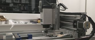
In order for the workpiece and the part to rotate synchronously, it is necessary to connect them with couplings. A sprocket and crown are suitable for control. The copy milling machine is ready. The design achieved 5 degrees of freedom. Movement along the X axis is ensured by the movement of the structure along rail guides, movement along the Y axis is ensured by the movement of a moving element along a polished shaft, and movement along the Z axis is ensured by the movement of rocker arms.
Additionally, due to the movable couplings, the probe and the milling cutter can move left and right along the axis of the rocker arm, and it is possible to move the template and the workpiece simultaneously. This makes it possible to process parts of almost any shape.
Types of copy-milling machines
The equipment of a copy-milling machine may include various types of drives. Based on this parameter, the following are distinguished:
- equipment with a pantograph (suitable for processing parts in 2–3 dimensions);
- devices with a copier mounted on a rotary rack moving in a vertical plane;
- single- and multi-spindle machines equipped with round or rectangular rotary tables;
- machines, the feed on which is ensured by mechanical, electrical, hydraulic devices;
- photocopying equipment.
A homemade copying machine can be any of these types (including copying and grinding machines). You just need to find drawings on the Internet and select components.
An example of a homemade copy-milling machine
According to the degree of automation and the method of fixing the workpiece, the following categories of copy-milling machines are distinguished:
- manual or desktop, on which the workpiece is fixed mechanically (on these devices you can drill holes of various shapes in accordance with the template);
- automatic equipment of a stationary type, the workpieces on which are fixed using pneumatic clamps (such machines work with aluminum);
- automatic equipment of a stationary type with pneumatic clamps, on which a three-spindle head is installed (on these copy-milling machines, triple holes are simultaneously drilled, which does not allow the production of units of the two previous types).
Principle of operation
The part that sets the characteristics during processing becomes copiers. The head at the table is the main tool for work, accepting movements on the working surface, contour. The repetition of movements is carried out using parts with cutters.
The work of the main elements is carried out with the main and auxiliary movements. The main thing is that when the spindle rotates and moves, the tools cut into the workpiece materials, and a table with a slide moves along the contour.
There are several types of auxiliary movements:
- Accelerating the movement of the table and slide.
- Moving installations, from tables with copying fingers, stop mechanisms, clamping.
Ordinary actions and the use of feedback are the two main types of circuits, the implementation of which is allowed for devices. A rigid connection with the copier is the basis of the simplest scheme, the direct variety. There is no connection when the movement is reversed. The tracking device transmits movements.
When a contour or volume is milled, machines of this type are ideal. If contour milling is used, it is assumed to use a plane that is parallel or perpendicular to the tool. The second case involves moving the table along or across. Volumetric version of work - when the part is processed in stages. When moving, several planes are used at once.
The pantograph also allows you to implement a direct scheme. It reduces the size of finished products compared to templates. Making your own devices, if necessary, will not be a hassle.
Safety precautions when working with a turning and copying machine
Following the advice of experts when working with a copying lathe will make it possible to avoid numerous unpleasant situations and damage:
- Always check the fastening of elements and protective parts.
- It is necessary to remove unnecessary objects from the machine.
- Tools must be in their place.
- The cutting tool is checked for correct sharpness and proper design.
- The feeding of the equipment is carried out smoothly and without pressure, only after reaching the full rotation speed.
If any malfunctions occur, it is recommended to contact a specialist or carefully inspect all components.
Wood is the most practical and natural material from which you can make household items, furniture and even children's toys. In addition, many residential and non-residential buildings are built from wood. Therefore, many “homemade craftsmen” are not averse to having woodworking machines for their home workshop. They can be purchased at a specialized store or made independently from scrap materials. Let's talk in more detail about the second method of arranging your own corner for work.