Of all the technological operations performed on metal workpieces, processing on turning equipment is the most common. This is why sharpening lathe cutters designed for metal work is a very important process that must be done correctly. The features of such a procedure depend both on the material to be processed and on the type of cutting tool itself (shaped, continuous, thread-cutting, boring, etc.).
The procedure for sharpening cutter surfaces
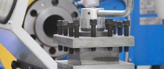
Types and design options for turning tool holders
Tool holder for a lathe: purpose and design. Varieties, their design features. Advantages of quick-release structures. Making a tool holder at home - video.
The tool holder is one of the most important blocks of lathes, used to secure the cutting tool. There are many modifications to the design of such a unit, intended for use in various conditions. In addition, universal tool holders for lathes are produced, which can also be used for other metal-cutting equipment. The quality of metalworking of a workpiece largely depends on the accuracy of the cutter holder.
Lathe cutter design
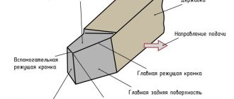
In the design of any cutter used for turning, two main elements can be distinguished:
- holder with which the tool is fixed on the machine;
- a working head through which metal processing is performed.
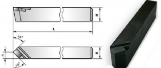
The working head of the tool is formed by several planes, as well as cutting edges, the sharpening angle of which depends on the characteristics of the workpiece material and the type of processing. The cutter holder can be made in two versions of its cross section: square and rectangle.
According to their design, turning cutters are divided into the following types:
- straight - tools in which the holder together with their working head are located on one axis, or on two, but parallel to each other;
- curved cutters - if you look at such a tool from the side, you can clearly see that its holder is curved;
- bent - the bend of the working head of such tools in relation to the axis of the holder is noticeable if you look at them from above;
- drawn - with such cutters the width of the working head is less than the width of the holder. The axis of the working head of such a cutter can coincide with the axis of the holder or be offset relative to it.
Types of cutters by design
Tools for turning equipment
In order to understand the rules for sharpening cutters for metal lathes, it is not enough just to watch a training video. It is necessary to have an idea of how such instruments are classified. The most important parameter according to which turning tools are classified into different types is the type of processing performed with their help. Based on this feature, the following types of turning tools are distinguished.
Main types of turning tools
With such cutters, workpieces are processed along the axis of rotation.
Using these cutters on a lathe, they reduce the ledges and trim the workpieces.
As the name suggests, they form external and internal grooves on cylindrical surfaces. You can also create grooves on the outer sides of workpieces using metal cutting tools. In addition, such cutters allow you to cut parts of the workpiece at right angles.
With the help of such tools, holes are processed on machines.
These cutters are specifically designed for cutting threads.
Using cutters of this type, shaped protrusions or grooves are formed on the outside of cylindrical workpieces.
With the help of these cutters, chamfers are removed from workpieces.
Operations performed with various types of cutters
Turning cutters are also divided into types depending on the direction in which they are used to process the workpiece. So, among them there are right-handed (processing is carried out towards the headstock) and left-handed (processing towards the tailstock).
Turning tools are classified according to the material of manufacture, the method of connecting the cutting part to the holder, and also according to a number of other parameters.
Installation of cutter
The tool is installed at an angle of 90 degrees to the workpiece being processed, in its center. A difference of a fraction of a millimeter leads to breakage of the cutter.
When turning brittle metals, the cutter is held at an angle of up to 10 degrees. Otherwise, the workpiece will break off faster than the cutter reaches the center. When working with high-speed tools made of solid metal, it is necessary to maintain a processing speed of no more than 30 mm per minute. Tipped carbide cutters operate at high speeds - up to 130 meters per minute.
Boring cutters and their installation
The holes are bored on lathes using boring cutters (Fig. 118). Depending on the type of hole being bored, they are distinguished: boring cutters for through holes (Fig. 118, a) and boring cutters for blind holes (Fig. 118, b). These cutters differ from each other in the main angle f. When boring through holes (Fig. 118, a), the main plan angle is φ = 60°. If a blind hole with a shoulder of 90° is bored, then the main angle in the lead is φ = 90° (Fig. 118, b) and the cutter operates as a thrust-through one, or φ = 95° (Fig. 118, c) - the cutter operates with longitudinal feed as a thrust feed, and then with a transverse feed as a scoring feed.
Boring cutter sharpening angles
In Fig. 118 shows the sharpening angles of boring cutters, which are chosen basically the same as for cutters for external turning, with the exception of the clearance angle a, which for boring cutters usually has an increased value. The size of the clearance angle depends on the diameter of the hole being bored: the smaller the diameter of the hole, the larger the clearance angle of the cutter should be.
Rice. 118. Boring cutters equipped with hard alloy plates: a – through-boring for processing through holes, b and c – persistent-through for processing blind holes
Complexity of the operation
Boring is a more complex operation than external turning of surfaces, since:
- when boring, the cross-sectional size of the cutter should be significantly smaller than the diameter of the hole, and the projection of the cutter from the cutting head is slightly greater than the length of the hole being bored (Fig. 119), therefore, when boring a hole of significant length, bending of the cutter is possible, and at high cutting speeds - strong vibrations. Consequently, such cutters do not make it possible to cut chips of large cross-section;
- When boring, it is less convenient to observe the work of the cutter, since cutting occurs inside the hole.
Rice. 119. Boring a hole with a cutter
For boring holes with a diameter of up to 70 mm, the innovative turner V.K. Seminsky proposed a special boring cutter equipped with a hard alloy plate (Fig. 120). The cutter shaft has a square cross-section along its entire length, the working part of the cutter is rotated by twisting during manufacturing at an angle of 45° relative to the supporting part. This cutter is characterized by increased rigidity compared to a conventional boring cutter and allows an increase in the chip cross-section by 4-5 times. When working with such a cutter at an increased cutting speed, no vibrations are observed even with a significant overhang of the holder.
Rice. 120. Boring cutter, equipped with a carbide plate, designed by V.K. Seminsky
To increase the vibration resistance of the cutter, the innovative turner V. Lacour proposed a new design of a boring cutter with a carbide plate (Fig. 121). The peculiarity of these cutters is that their main cutting edge is located at the level of the neutral axis of the rod. This arrangement of the cutting
Rice. 121. Boring cutter designed by V. Lakura
edge provides the cutters with a significant increase in vibration resistance and, as a result, makes it possible to work at high cutting speeds and achieve improved cleanliness of the machined surface.
Rice. 122. Mandrel with a cutter for boring a through hole
Installation of cutter
Long holes are bored with cutters fixed in special massive mandrels, the dimensions of which depend on the diameter of the hole and its length. Replacing a solid boring bar with a small cutter inserted into a boring bar provides significant savings in expensive tool material. The method of attaching the cutter to the mandrel depends on its purpose. In Fig. 122 shows a mandrel for boring a through hole; here the cutter is located at a considerable distance from the end of the mandrel. To bore blind holes, the cutter is attached in such a way that it protrudes slightly beyond the front end of the mandrel.
Before boring the hole, it is necessary to set the cutter to the required diameter along the dial of the cross-feed screw, and then bore the hole by hand to a length of 2-3 mm. After measuring the diameter with a caliper or other measuring device and making sure that the size is correct, bore the hole to the remaining length. It is especially important to correctly set the cutter to the required diameter when finishing boring.
The position of the cutting edge of the cutter depends on the type of boring. When rough boring, it is recommended to set the cutting edge at the height of the centers or slightly lower. When finishing boring, the cutting edge must be positioned above the center line by approximately 1/100 of the hole diameter, taking into account that due to the force arising from the resistance of the cut chips, the cutter can be pressed down.
Similar materials
www.metalcutting.ru
Using the tool holder
The tool holder is a separate unit of the machine, secured with bolts. It greatly facilitates the processing of parts. The use of a tool holder is especially important when accurately boring holes. The designs of tool holders are highly durable and reliable, since even a small backlash can significantly reduce the processing accuracy.
The turning tool holder is designed to accommodate the cutter in height and in the horizontal plane. The height setting of the tool holder is of great importance for the machining process. If turning is performed, the cutter is installed so that the cutting edge of the tool is higher than the center line of the machine. For boring, the cutter is placed below the center line.
Simple tool holder
The simplest design has a tool holder called a “soldier”.
This device has a spherical backing that allows you to quickly secure the cutter. By rotating the spherical spacer, the cutting angle and height position are adjusted. The cutter is secured using one bolt. On the one hand, this device of the lathe tool holder makes it possible to install the cutter in a minimum time, and on the other hand, the entire load falls on one bolt, so it must be tightly tightened. However, in an attempt to provide sufficient clamping, this bolt is often overtightened, causing the thread to quickly become unusable. As a result, the bolt breaks or the internal thread is cut off. Repairing such a tool holder involves replacing the bolts and boring the hole to a larger size. It is also possible to install a threaded bushing into the hole. To increase the durability of bolts, they are made from strong steels, such as 12ХН3А, carburized to a depth of 0.6-0.8 mm and hardened, which makes it possible to achieve a surface hardness of 50-60 HRC. Thanks to this, the durability of bolts increases by 10-15 times compared to raw bolts made from steel 45, however, their price also increases. For most of the tool holder parts, 45 steel is used, whose hardness is in the range of 220-260 HB.
Installation of cutters in the tool holder and workpieces in the chuck
Installation of cutters in the tool holder and workpieces in chuck
K
category:
Turning
Installation of cutters in the tool holder and workpieces in the chuck
Installation of the cutter. Before you start working on the machine, you need to install the cutter in the tool holder in the center and secure the workpiece (part) in the chuck.
There are fixed and rotating centers. They serve as a support for the long workpiece being turned. The centers are secured in the tailstock quill.
Having established the center in the quill, by rotating the handwheel, bring the apron with the caliper close to the tailstock. Then the cutter is secured in the tool holder using screws. The head of the cutter should protrude from the tool holder no more than 1.5 times the height of the rod, and the top of the cutting edges of the cutter should coincide with the tip of the center.
If the tip of the cutter is below the center tip, then one, two or three pads, selected in thickness, are placed under the rod. The shims are made of sheet steel; their width and length must correspond to the size of the cutter rod.
By selecting shims of appropriate thickness, the tip of the center coincides with the top of the cutting edges of the cutter. Then, using a key, secure the cutter with screws, and the tool holder with a handle.
The rules for installing all cutters are the same.
Installation of the workpiece in the chuck. The workpieces to be turned are secured to the machine spindle using various devices. The most convenient is a three-jaw chuck. It is designed very simply: in a housing with square holes for the key there are three movable cams.
The workpieces are secured in the chuck as follows. By rotating the key inserted into the square holes of the chuck, the cams are moved apart. Then place the workpiece between them and turn the key to bring the cams together; they must clamp the part firmly. The length of the part of the workpiece protruding from the chuck should not exceed three of its diameters.
Rice. 1. Centers: a - motionless; b - rotating
Rice. 2. Installation of the cutter (given conditionally)
Rice. 3. Three-jaw chuck
Remember!
The workpiece must be secured with a key from the side of each cam; to do this, the chuck is turned 1-2 turns.
Tool structure. A caliper is a universal measuring tool.
Rice. 4. Caliper ShTs-1 with a reading accuracy of 0.1 mm
It can be used to measure the thickness of parts, the width and depth of holes.
There are millimeter divisions on the tool's ruler bar. Together with the ruler, two fixed jaws are made: one for measuring external, that is, external, dimensions; the other is internal dimensions. The rod is fitted with a frame with movable jaws and a depth gauge, which is a thin, narrow ruler. The depth gauge is placed in the longitudinal groove on the back side of the ruler.
The frame can be freely moved along the rod and secured in the desired position with a screw. On the bevel of the lower part of the frame there are divisions (scale). This additional measuring device is called a vernier (Fig. 129). Vernier allows you to more accurately determine the dimensions of parts down to a tenth of a millimeter.
You all know that one centimeter is equal to ten millimeters. But we can say and write differently: a millimeter is one tenth, or simply a tenth, of a centimeter, that is, 1 mm = 1/10 cm = 0.1 cm. If you divide a millimeter into 10 parts, then each part is called one tenth of a millimeter and written as follows: 0.1 mm.
The length of the vernier is 19 mm, and the scale is divided into 10 equal parts. Thus, each division of the vernier is equal to 1.9 mm, i.e. 0.1 mm less than two millimeter divisions of the rod.
When the caliper jaws are closed, the zero division (initial) and the last division of the vernier coincide, respectively, with the zero and nineteenth divisions of the rod (less than 1 mm from mark 2). The remaining divisions of the vernier and the rod should not coincide.
Rice. 5. Vernier caliper
Rice. 6. Taking measurements with a caliper (a) and counting using a vernier (b)
Measuring with a caliper. Read the readings of the caliper, that is, determine the dimensions of the part as follows.
Whole millimeters are counted by divisions of the rod to the zero mark of the vernier. In our example, the zero division of the vernier is between the whole values (42 mm and 43 mm) of the scale. The number of whole millimeters on the rod in our example is 42. Then it is determined which division of the vernier coincides with the division of the rod. The serial number of the matching vernier division shows the number of tenths of a millimeter—in our case, the fifth division. So, the size of the part being measured is 42.5 mm.
Advertising:
Read more:
Turning of cylindrical workpieces with manual feed
Related articles:
pereosnastka.ru
Threading tools
Thread cutting using lathe equipment
Shaping on the machine is carried out by copying the working profile of the tool onto the part along a helical line. Translational movement is transmitted to the cutter, tap, die, comb. In combination with the rotation of the workpiece, a screw movement is obtained, the tool surface coincides with the cut surface.
As a rule, cutting small batches of fasteners and fittings up to M36 is carried out using taps and lechers. It is more profitable to produce large orders using specialized machines. Large-diameter threads, running threads, power threads, and precision threads are processed with cutters on universal lathes when CNC models are not available or the production program is insufficient.
Cutting internal and external threads with a cutter
Threads with high coaxiality to other surfaces, transmitting movement and force are performed with a cutter. The rotation of the spindle is connected kinematically to the lead screw, which moves the support with the tool holder.
The general procedure includes:
- Grooving the surface along the length of the cut, forming a groove for the tool to exit.
- Selection, if necessary: sharpening, finishing of the cutter with checking using corner templates.
- Setting modes on the machine, tuning the guitar to a pitch not provided by the box.
The movement of the cutter per revolution of the workpiece is equal to the step P or the move H for multi-start ones.
- Installation of the cutter according to the template.
- Cutting for the number of passes selected from the directory.
Thread cutting of a batch of parts is divided into rough and finishing. For the latter, the tool is carefully sharpened. Threads with pitches greater than 2 mm are produced by lateral cutting. The left helical groove is obtained by switching the bit so that the lead screw rotates in the direction opposite to the spindle. The support with the cutter moves from left to right.
Average speeds when threading steel are 20–35 m/min with high-speed cutting tools, 100–150 m/min with carbide tools. Finishing strokes are performed at a speed increased by 50–100%. Internal threads are processed at 30% reduced conditions.
Using taps
The widespread grade R6M5 allows cutting workpieces with a hardness of up to 240 HB; taps made from tool alloy steels are used for “raw” parts. Carbide ones are rarely used, since the edges are chipped due to distortions and misalignment, which increase bending loads.
Installation and fastening of the cutter | Turning
Before grinding, you need to correctly install the cutter in the cutting head. It is necessary to ensure that the protruding part of the cutter is as short as possible - no more than 1.5 times the height of its shaft. With a larger overhang, the cutter will vibrate during operation and, as a result, the machined surface will be unsmooth or wavy, with traces of crushing.
In Fig. Figure 31 shows the correct and incorrect installation of the cutter in the cutting head.
Rice. 31. Installation of the cutter in the cutting head
In most cases, it is recommended to set the tip of the cutter at the height of the machine centers. To do this, use linings (no more than two), placing them under the entire supporting surface of the cutter (Fig. 32).
Rice. 32. Installation of the cutter using shims Fig. 33. Checking the installation of the cutter according to the height of the centers
The pads are flat steel plates, usually 150-200 mm long. The turner must have a set of such pads of different thicknesses. Random pads should not be used.
In Fig. Figure 32 shows the correct and incorrect installation of the cutter using shims.
To check the position of the tip of the cutter according to the height of the centers, bring it to the pre-calibrated rear center, as shown in Fig. 33. For this purpose, you can use a mark placed on the tailstock quill at the height of the center.
The fastening of the cutter in the cutting head must be reliable and durable: the cutter must be secured with at least two bolts. The bolts securing the cutter must be tightened evenly and tightly.
Similar materials
www.metalcutting.ru
Cutter design
All turning tools consist of two structural elements:
- holders with a rectangular or square cross-section, which is used for fixation in the tool holder;
- head - a working part consisting of several cutting edges.
According to the shape of the holder, the cutters can be:
- straight;
- curved;
- bent;
- pulled back.
According to the method of production they are:
- Monolithic (solid).
- Napaynymi.
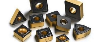
- With mechanical fastening of replaceable plates.
The working part is formed by several planes and cutting edges, the shape of which depends on the purpose of the tool. Most cutters are manufactured in left and right hand versions and are selected according to the feed direction.
Inverted cutting cutter
inverted cutter
Cutting work is especially difficult on amateur machines with low speeds and poor technical characteristics. You can resharpen a standard cutting tool, but this work is long and painstaking; the tool will turn out to be quite fragile, requiring extreme care in work.
To solve this problem, the design of an inverted cutting cutter was invented. These are tools with replaceable carbide steel inserts. They can be used in forward and reverse rotation. Moreover, the main mode for this tool is reverse rotation, when chips separate unhindered, they are easy to remove from the work area, and jamming occurs less frequently.
The design provides for height adjustment of the cutter using an insert triangle and a T-shaped profile of the cutting blades. This shape reduces friction during penetration into the material. The kit usually comes with 4 - 5 options for cutting blades. They can be sharpened many times as long as the length allows.
The long overhang of the cutting blade is very convenient, thanks to which you can cut off thick workpieces; it is advisable to lubricate them during operation. The tool is good for making narrow grooves, especially where the planes touch.
Table of contents
Types of bent cutters Main dimensions of bent cutter Geometry of bent cutter Selection of bent cutter Cutting modes Marking
download price list TURNING CUTTERS
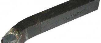
A bent cutter is used for turning the outer surfaces of rotating parts, which include long conical surfaces, cylindrical rollers and other things. Unlike straight ones, bent through cutters have become more widespread, since they have universal capabilities in work. They have higher rigidity and, due to their shape, they can process parts even in hard-to-reach places. They are used to create parts, rough and finish processing of workpieces in mechanical engineering and machine tool building; in almost every professional turning workshop, a bent cutter is an indispensable tool for processing.
Types of incisors
Boring cutters are divided into several subgroups, depending on the main parameters.
Feed on the machine can have several directions. Considering this fact, the incisors can be: left; right. For each type of hole, the required design of the equipment . The accuracy of processing and operation time depend on this. Depending on its design, the tool is divided into several types:
- Direct. The axis of the holder coincides with the line of the cutting head. Sometimes the parallelism of the axes is maintained.
- Bent back. The axis of the tool head can deviate in a certain direction from the axis of the holder.
- Curved. The holder has a curved axis.
- Retracted. The holder is wider than the tool head.
It must be said that sometimes such forms are not enough. Especially when the part has a complex shape. Especially for such cases, designers are developing unique types of boring tools .
The shape of the holder divides the cutters into several types:
- Round.
- Rectangular.
- Square.
The classification of a tool is also influenced by the manufacturing method. The equipment is divided into groups:
- Solid. The tool is made of a homogeneous material.
- Composite. A carbide plate is used to make the cutting part. It can be fixed to the holder with a regular bolt or soldered.
Installation of turning tools.
| Installation of cutter | Changing cutter angles | The influence of changing cutter angles on the cutting process | Rules |
| Rough turning | |||
| The cutter is installed above the center |
| Cutting conditions improve, since as γ , the degree of chip deformation decreases. a decrease in α can increase the friction of the rear edge of the cutter on the machined surface to unacceptable limits | In general, the cutter is installed above the center. When peeling long and thin workpieces, the cutter must be installed in the center to avoid jamming due to the springing of the workpiece. when peeling very hard materials (i.e., with high cutting forces), the cutter should be installed below the center to avoid jamming of the cutter due to its deflection under the influence of the cutting force. |
| The cutter is installed below the center |
| Cutting conditions worsen (see above). Increasing α does not improve the chip separation process. | |
| Finish turning | |||
| The cutter is set above the center | Angles γ, δ and α change depending on the installation of the cutter in the same way as when changing the position of the cutter relative to the center during grinding work (see above) | The reduction in cutting force resulting from installing the cutter above the center is insignificant in this case due to the small size of the chips being removed. The phenomenon of retraction of a cutter installed above the center into the workpiece is accompanied by vibration of the cutter, as a result of which the processed surface is not smooth. | The cutter should be installed at the height of the center or even slightly below it, but in no case above the center. |
| cutter set at center height | When installing the cutter at the height of the center, the cutter moves away from the workpiece and jamming does not occur. | ||
| Rough boring | |||
| The cutter is set below the center |
| Cutting conditions improve, since chip bending decreases γ A decrease in α can increase the friction of the rear edge of the cutter on the machined surface to unacceptable limits | The cutter should be installed at or below center. Excessive lowering of the cutter can cause an unacceptable reduction in α. Increasing this angle by grinding the back edge will cause a decrease in the sharpening angle of the cutter, i.e. will reduce its strength and ability to remove heat. |
| The cutter is set above the center |
| Cutting conditions worsen (see above). Increasing α does not improve the chip separation process. | |
| Finish boring | |||
| The cutter is set at center height | Angles γ, δ and α change depending on the installation of the cutter in the same way as when changing the position of the cutter relative to the center during grinding work (see above) | The reduction in cutting force resulting from installing the cutter below the center is insignificant in this case due to the small size of the chips being removed. But even with a slight pressure, the cutter installed below the center and at the height of the center will be released, as a result of which the diameter of the hole will increase, which in this case is unacceptable. | The cutter should be installed above the center or at the height of the center, but in no case below it. |
| The cutter is set above the center | When installing the cutter above the center, it will also lower, but the diameter of the hole being bored will decrease, which can be corrected by subsequent processing. | ||
bs111.ru
Sharpening cutters
Sharpening of turning tools is carried out both during their manufacture and during wear. The sharpening process takes place on sharpening and grinding machines with continuous cooling. First, the main surface is sharpened, then the back and auxiliary. After this, the front surface of the cutter is processed until a smooth cutting edge is obtained.
Each cutter sharpening machine has two grinding wheels: one made of electrocorundum and one made of green silicon carbide. The first is used for processing high-speed steel cutters, the second is used for sharpening carbide cutters. To check the correct sharpening of the cutter, there are special templates.
Tools such as turning cutters are in fairly good demand and are widely represented in the catalog assortment.