Lathe scoring cutter is a cutting working tool of a lathe, with which you can perform the following simple operations:
- remove allowances on cylindrical or conical workpieces;
- smooth the surface to be processed, give the part a given shape;
- form chamfers;
- cut off ledges;
- grind the ends;
- remove excess elements on the outer surface of the workpiece.
The lathe scoring cutter is rigidly fixed on the lathe. During operation, it cuts into the material of the part to a set depth and removes it in the form of chips.
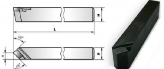
Geometry characteristics
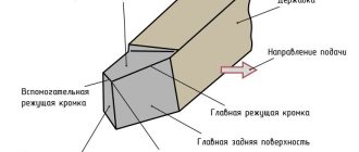
All cutter models have similar geometry and consist of the following main parts:
- The head is the main working section, usually made of steel alloy.
- Rod (body) – needed for fastening in a lathe.
- Support surface - it is used to fix the turning tool in the machine holder.
- Rake surface – ensures chip rollback from the surface of the workpiece.
- The main cutting edge is the one that cuts the part.
- The tip of the blade is the point where the cutting tool touches the workpiece.
- The main back surface supports the plate during operation.
- Rear auxiliary surface - allows the tool to move smoothly along the surface while processing the workpiece.
Experts often group the listed elements of scoring cutters into two main structural units. The rod and the supporting surface form a holder, which acts as a clamp on the machine. It can be rectangular or square in cross section.
Both surfaces of a lathe scoring cutter represent a working part, which is called the head. The sharpening angle of the cutters depends on the properties of the material of the plates and workpieces, as well as the processing technology.
Type 1
Damn.1
Damn.2
Table 1
Dimensions in mm
| Designation of plates according to GOST 25397-90 | |||||||||||||||
| Cutter section | Insertion angle | Insertion angle | |||||||||||||
| 10° | 0° | 10° | 0° | 10° | 0° | 10° | 0° | ||||||||
| 12x12 | 15 | 3,9 | — | ||||||||||||
| 15 | 9,5 | 6,4 | 4 | ||||||||||||
| 16x16 | 20 | 4 | 7,4 | 6,0 | 6,5 | 06010 | |||||||||
| 28 | 12,0 | 5,5 | 8,0 | 5 | |||||||||||
| 48 | — | ||||||||||||||
| 25 | 15,0 | 5 | 9,4 | 6,8 | 7,4 | 6,6 | 9,6 | 6 | 06030 | ||||||
| 55 | |||||||||||||||
| 20x20 | 17,0 | 6 | 11,1 | 8,5 | 9,2 | 7,0 | 7,2 | 9,2 | 11,2 | 7 | 06050 | 66050 | |||
| 64 | |||||||||||||||
| 25x25 | 48 | 24,0 | 8 | 15,0 | 12,1 | 13,0 | 10,0 | 10,2 | 12,7 | 15,2 | 9 | 06090 | 66090 | ||
| 78 | |||||||||||||||
Damn.3
Damn.4
table 2
Dimensions in mm
| Designation of plates according to GOST 25397-90 | ||||||||||||
| Cutter section | Insertion angle | Insert angle | Insert angle | |||||||||
| 10° | 0° | 10° | 0° | 10° | 0° | 10° | 0° | |||||
| 16x12 | 6,0 | 11,1 | 8,5 | 9,2 | 11,8 | 12 | 14,0 | 10 | 12 | 06050 | 66050 | |
| 20x16 | 8,0 | 15,0 | 12,1 | 13,0 | 14,8 | 15 | 17,5 | 12 | 16 | 06090 | 66090 | |
| 25x20 | 10,0 | 18,8 | 15,7 | 16,9 | 18,8 | 19 | 22,0 | 16 | 21 | 20 | 06130 | 66130 |
| 32x25 | 12,5 | 23,6 | 17,3 | 18,6 | 24,7 | 25 | 28,5 | 20 | 23 | 22 | 06170 | 66170 |
| 40x32 | 30,3 | 16,6 | 18,3 | 30,6 | 31 | 35,5 | 28 | 22 | 21 | 06270 | 66270 | |
GOST 18880-73 (download PDF)
Varieties and classification
Lathe scoring cutters are produced by Russian and foreign manufacturers. There is a large assortment on the market, so they are grouped as follows:
- According to manufacturing technology: solid, composite.
- The level of processing they provide: roughing, semi-finishing, finishing;
- The direction of delivery is either right or left.
Lathe scoring cutters are called solid if they are completely made of tool steel of the same grade; for composite (prefabricated) ones, the elements are made of alloys with various additives. The holder is made from particularly strong and wear-resistant metal that can withstand long-term shock loads. The working head is made of carbide material, but, in addition, it should not heat up during operation.
For example, hard alloy T10K5 is suitable for the manufacture of a holder, and high-speed steel R9 is suitable for the cutting insert located on the head.
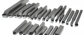
Prefabricated tools, with interchangeable inserts of various widths and thicknesses, are becoming increasingly popular. Cannot be sharpened. In addition, some of them have adjustable head extension length.
The characteristics of cutters made of carbide alloy must comply with the international standard GOST 18880-73, and those of high-speed steel GOST 18871-73.
Depending on the purpose and operating principle, the following types of cutters are produced.
Straight models
Their cutting edges are located parallel to the axis of the holder, they are smooth, without bends. Used for rough processing and grinding off excess areas, removing a significant layer of material. This will require several approaches. They did not gain much popularity.
Turning cutters, bent scoring
They perform similar functions, and also add the ability to process shaped surfaces. The curved shape allows you to grind hard-to-reach places and penetrate into the middle of parts, but are not suitable for finishing. The working part has a triangular cross-section and is curved relative to the holder axis. With such a cutter, a metal product must be processed perpendicular to the axis of rotation.
Toolholders come in only three standard sizes: 16x10, 25x16 and 32x20 mm.
Turning scoring thrusters
Such turning scoring tools are used to process parts made of materials of low rigidity. They are used for cutting thick layers of metal in one pass, as well as for trimming edges and grinding down stepped surfaces. The cutting edges and the axis of the holder are parallel.
Based on the direction of feeding, instruments are classified into left-handed and right-handed, which can be distinguished visually if you place your palm and look at the direction of your thumb.
I. TECHNICAL REQUIREMENTS
I. TECHNICAL REQUIREMENTS
1. As the cutting part of the cutter, soldered carbide inserts should be used from grades of carbide of application groups P01...P50, M10...M40, K01...K40 according to GOST 3882.
It is allowed to use plates in accordance with other technical documentation approved in the prescribed manner.
(Changed edition, Amendment No. 6).
2. Holders for turning, scoring, boring type 2 and boring holder cutters with a height of more than 12 mm must be made of steel grade 45 or 50 according to GOST 1051 group B for general purpose, and holders of the same cutters with a height of up to 12 mm incl. — made of steel grade 40X according to GOST 1051 group B for general purpose.
It is allowed to use steel grades 45 and 50 according to GOST 1050 and grade 40X according to GOST 4543.
The holders of planing and scoring cutters must be made of steel grade 45 or 50 according to GOST 1050, and the holders of planing and turning cutting and slotting cutters and turning boring cutters of version 1 should be made of steel grade 40X according to GOST 4543 and steel grade 45 or 50 according to GOST 1050 .
It is allowed to manufacture cutter holders from structural powder steels with a density of at least 6.9 g/cm.
(Changed edition, Amendment No. 3, 4, 5, 6).
3. Protrusion of the cutting insert relative to the cutter holder is allowed. The amount of protrusion of the insert should not exceed the thickness of the cutting insert:
| up to 5 mm | 0.5 mm | ||
| over 5 mm | 1.0 mm | ||
The amount of plate protrusion for cutting, slotting and revolving cutters should not exceed 0.5 mm.
The depth of the groove for the cutting plate on the cutter holders should be 0.5-0.75 of the thickness of the cutting plate. For cutters with a holder cross-section equal to 12x12 mm or with a holder diameter equal to or less than 12 mm, the groove depth can be equal to the thickness of the plate (Fig. 1).
Damn.1
When diamond sharpening, overhang of carbide plates of up to 0.8 mm is allowed.
The depth of the groove of the parting cutters must be equal to the thickness of the plate.
Solders of P102 and PrMNMTs 68-4-2 brands should be used as solder.
The use of solder grades PrANMts 06-4-2 and P100 is allowed.
The solder layer should be no more than 0.35 mm thick.
In the seam around the perimeter and in the corners of the seam, single places without soldering (pores) are allowed.
Breaks in the solder seam between the supporting surfaces of the cutting insert and holder should not exceed 10% of the visible length of the solder seam on through and scoring cutters and 5% on slotting and parting cutters. Solder breaks under the main cutting edge are not allowed.
On the side supporting surfaces of the cutting insert, the total length of the gaps should not exceed 50% of the length of the solder seam. Solder residues are allowed on the holder under the plate on the rear and front surfaces of the cutters if these surfaces extend beyond the holder.
(Changed edition, Amendment No. 4, 5, 6).
4. Cracks, chipping and traces of solder are not allowed on the front and back surfaces forming the cutting edge and rounding of the apex.
On non-working edges and corners, chipping is allowed, the magnitude of which should not exceed those indicated in Table 1a.
Table 1a
mm
| Insert thickness | Allowable chip size | |
| over | before | |
| 2 | 0.3x0.5 | |
| 2 | 5 | 0.4x0.8 |
| 5 | 10 | 0.6x1.2 |
| 10 | 0.8x2.0 | |
(Changed edition, Amendment No. 4, 6).
5. The front and rear surfaces forming the main cutting edge, including the curved section at the tip of the cutter, must be subjected to finishing operations.
The curved front surface, shaped like a hole, is not subject to finishing.
For cutters, the front surface of which is formed by two intersecting planes, only the surface adjacent to the main cutting edge should be polished.
6. The roughness parameters of cutters according to GOST 2789 should not exceed the specified values, microns, of the front and rear surfaces and the curved surface at the apex:
| subjected to fine-tuning | 0,4 | ||
| not subject to fine-tuning | 0,8 | ||
| auxiliary rear surface | 1,6 | ||
| supporting surface | 3,2 | ||
| side and top surfaces of holders of boring holder and turret cutters | 3,2 | ||
| other treated surfaces | 10 | ||
It is allowed, by agreement with the consumer, not to sharpen and fine-tune cutters on the front surfaces, and cutting cutters and on auxiliary rear surfaces.
(Changed edition, Amendment No. 6, 7).
7, 8. (Excluded, Amendment No. 4).
9. The connection between the main and auxiliary cutting edges should be smooth and correspond to the curve described by the radius. Abrupt transitions are not allowed.
10. The surfaces of the cutter holder must have a protective or protective-decorative coating in accordance with GOST 9.301 and GOST 9.306.
Protective or protective-decorative coatings should not violate the flatness of the supporting surface of the incisors.
It is allowed, by agreement with the consumer, to produce cutter holders without a protective or protective-decorative coating.
(Changed edition, Amendment No. 7).
11. Maximum deviations in the dimensions of turning and planing cutter holders must not exceed the specified values, microns:
| heights and widths of cold-drawn steel cutters with one machined support surface | h 16 | ||
| cutter heights made of hot-rolled steel with one machined bearing surface | h 17 | ||
| height, width and diameter of turret, turning, bent and boring holder cutters with all machined surfaces | h 11 | ||
| boring cutters with round holder section | h 9 | ||
(Changed edition, Amendment No. 4).
12. (Deleted, Amendment No. 4).
13. For cutters in which the height of the cutting edge corresponds to the height of the holder, the maximum deviations of the tip of the cutting edge should not exceed: tolerance ± IT 14 - for turning cutters, ± IT 11 - for boring cutters.
For cutters in which the height of the cutting edge does not correspond to the height of the holder, the maximum deviations of the tip of the cutting edge are not determined.
For cutters with a symmetrical cutting part, the maximum deviations from the symmetry of the cutting inserts (for wide cutters) or tips (for pointed cutters) relative to the width of the holder should not exceed tolerance IT 14.
The maximum deviations from the symmetry of the cutter tip relative to the width of the cutting plate should not exceed half of the IT 15 tolerance (Fig. 2).
Damn.2
(Changed edition, Amendment No. 4).
14. (Deleted, Amendment No. 4).
15. Maximum deviations in the width of the working part of cutting and slotting cutters should not exceed those indicated in Table 1.
Table 1
mm
| Nominal working width | Maximum deviation of the width of the working part of the cutter | |
| slotted | cutting | |
| 3, 4, 5 | +0,1 -0,35 | +0,2 -0,5 |
| 6, 8, 10 | +0,1 -0,4 | +0,2 -0,5 |
| 12, 16, 18 | +0,2 -0,6 | +0,2 -0,6 |
| 20, 25 | +0,2 -0,7 | +0,2 -0,7 |
(Changed edition, Amendment No. 3, 5).
16. The maximum deviations of cutters up to 50 mm long should not exceed a tolerance of ±IT 16, and for cutters with a length of more than 50 mm, a tolerance of ±2 IT 16.
(Changed edition, Amendment No. 4).
17. Permissible deviations for the length of the drawn part of slotting, cutting and boring cutters should not exceed:
| for cutters with drawn length up to 20 mm | ±1 mm | ||
| for cutters with a drawn-out length of more than 20 to 50 mm | mm | ||
| for cutters with a drawn-out length of more than 50 mm | mm | ||
18. (Deleted, Amendment No. 6).
19. The flatness tolerance of the lower supporting surface of the cutter holder must correspond to the 10th degree of accuracy according to GOST 24643. Convexity is not allowed.
It is allowed to manufacture cutters with a flatness tolerance of the lower supporting surface of the cutter holder, no more than, mm: 0.1 - for cutters up to 50 mm long; 0.2 - for incisors over 50 mm long.
(Changed edition, Amendment No. 6, 7).
20. The straightness tolerance of the sides of the holder of turning and planing cutters should not exceed 1 mm per 100 mm of length.
In the case of cutting on presses, jams are allowed at the end of the holder of turning and planing cutters, the dimensions of which should not exceed those indicated in Table 2.
table 2
mm
| Height of cutter holder, | Zamin | |
| along the holder | by holder height | |
| 6-12 | 2 | 0,8 |
| 16; 20 | 3 | 1,0 |
| 25; 32 | 5 | 1,5 |
| 40; 50; 63 | 7 | 2,0 |
(Changed edition, Amendment No. 3, 4, 6).
21. Maximum deviations of the angles of the cutting part of the incisors (Fig. 3) should not exceed:
Damn.3
| front main angle up to 10° | ±1° | ||
| over 10° | ±2° | ||
| rear main angle () up to 10° | ±1° | ||
| over 10° | ±2° | ||
| main plan angle | ±2° | ||
| auxiliary lead angle () | |||
| up to 2° | ±0°30′ | ||
| at over 2° to 5° | ±1° | ||
| at over 5° | ±2° | ||
| cutting edge angle () | ±1° | ||
| main lead-in angle and back auxiliary lead-in angle for parting and slotting cutters | ±0°30′ | ||
22. Maximum deviations from the perpendicularity of the side surfaces relative to the supporting surface of the cutter should not exceed:
| for cutters machined only on the supporting surface | ±2° |
| for cutters with all machined surfaces | ±1° |
| for boring cutters | ±0°30′ |
| for slotting and parting cutters | ±1° |
21, 22. (Changed edition, Amendment No. 4).
22a. The average service life of cutters must be at least 45 minutes, the established service life period must be at least 20 minutes, under the operating conditions specified in the general machine-building cutting standards for turning and rotary work.
(Introduced additionally, Amendment No. 5).
22b. The criterion for dullness is the achievement of flank wear indicated in Table 4.
Table 4*
_________________ * Table 3. (Excluded, Amendment No. 5).
| Cutter type | Processed material | Allowable wear on the rear surface, mm |
| Pass-through straight and bent, push-through persistent | Steel | 0,8 |
| Cast iron | 1,2 | |
| Boring | Steel | 0,6 |
| Cast iron | 1,0 | |
| Cut-off and slotted | Steel, cast iron | 0,8 |
(Changed edition, Amendment No. 6).
Continuation of Table 4
| Cutter type | Processed material | Allowable wear on the rear surface, mm |
| Threaded for pitch: | ||
| up to 3 mm | Steel, cast iron | 0,2 |
| St. 3 mm | Steel, cast iron | 0,4 |
| Planing | Steel, cast iron | 0,8 |
22c. On one of the sides of each cutter the following must be applied:
manufacturer's trademark;
width of the cutting part for slotted cutters;
grade of hard alloy;
cutter designation (last four digits);
image of the state Quality Mark when it is assigned in the manner established by the USSR State Standard.
22g. Transport marking and marking of consumer packaging - in accordance with GOST 18088.
22d. Internal packaging option VU-1 - according to GOST 9.014.
22nd Other packaging requirements are in accordance with GOST 18088.
22c-22e. (Introduced additionally, Amendment No. 6).
23, 24. (Excluded, Amendment No. 4).
Selection criteria
Depending on the material of the workpiece and the type of operation that needs to be performed using a cutter, the appropriate type of tool is selected.
For turning work, it is necessary to purchase lathe scoring cutters of different models: first, rough processing is performed with one type, then the tool is replaced to perform finishing processing.
There are several factors that should be taken into account when choosing a lathe scoring cutter:
- The material of the workpiece should not be more rigid than the tool itself.
- The need to comply with the dimensions and quality of surface treatment of the product.
Take into account the wear resistance of the tool, which directly depends on the strength of the material being processed.
It must be taken into account that the main elements can be made of different materials depending on the functions performed. For example, in order for the holder to provide reliable fixation in the tool holder, it must be shock-, heat- and wear-resistant.
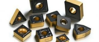
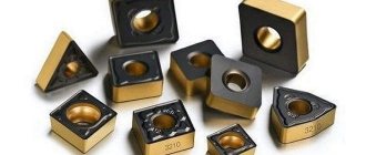
Manufacturers typically use two types of materials to make cutting inserts:
- High speed steel. This alloy is characterized by relatively low strength, so tools are not recommended for processing hard materials. Such products become dull quickly. A large layer of material can only be removed gradually, over several approaches.
- Carbide materials. They are universal due to their special strength and super durability. Such properties are imparted by introducing, for example, cobalt or titanium into the alloy. To prevent tools from becoming too expensive due to expensive additives, a combined material of high-speed and carbide steel is used. Such products will also last a long time.
Working video, enjoy watching.
The consumer properties of turning scoring cutters can be assessed by markings indicating the grade of the alloy with the designation of alloying additives. For example, the T15K6 product is made of steel, which contains titanium carbide and cobalt, and the numbers indicate their percentage.
Nowadays, the inscription “HSS” is increasingly found on lathe scoring cutters. This designation indicates that the turning cutter is made of alloy steel, which is popularly nicknamed “quick cutter.” This is alloy steel, into which additional components are introduced to improve physical and mechanical properties. It follows from this that the composition of steel may be different for different cutters. It could even be cheap powder steel.
All these parameters influence the further choice of feed and cutting speed values, as well as tool life, i.e. the duration of continuous work until the cutting edges become dull.
yt-shzhpshnts
4 GOST 20872-80
A - A
5 4 1
1 - holder; 2 — cutting plate according to GOST 19046-80; 3 — support plate according to GOST 19073-80; 4 - wedge; 5 - screw; 6 - pin
Crap. 3
Table 3
mm
| Right incisors | Left incisors | Cutter section h ■ b | TO | TO | L | Pos. 2. Cutting plate according to GOST 19046-80 Qty. 1 | Pos. 3. Support plate according to GOST 19073-80 Quantity. 1 | |
| Designated reading | Apply bridge | Designated reading | Apply bridge | |||||
| Designation | ||||||||
| 2103-0671 | 2103-0672 | 1616 | 16 | 19 | 20 | 125 | 01114-160304 | 701-1604 |
| 2103-0673 | 2103-0674 | 01114-160308 | ||||||
| 2103-0675 | 2103-0676 | 01114-160312 | ||||||
| 2103-0677 | 2103-0678 | 01114-160408 | 701-1603 | |||||
| 2103-0681 | 2103-0682 | 01114-160412 | ||||||
| 2103-0695 | 2103-0696 | 20-20 | 20 | 24 | 25 | 150 | 01114-220408 | 701-2204 |
| 2103-0697 | 2103-0698 | 01114-220412 | ||||||
| 2103-0701 | 2103-0702 | 01114-220416 | ||||||
| 2103-0711 | 2103-0712 | 25-25 | 25 | 29 | 32 | 01114-220408 | ||
| 2103-0713 | 2103-0714 | 01114-220412 | ||||||
| 2103-0715 | 2103-0716 | 01114-220416 | ||||||
| 2103-0717 | 2103-0718 | 32-25 | 32 | 36 | 170 | 01114-220408 | ||
| 2103-0721 | 2103-0722 | 01114-220412 | ||||||
| 2103-0723 | 2103-0724 | 01114-220416 | ||||||
| 2103-0725 | 2103-0726 | 32-32 | 40 | 01114-270612 | 701-2704 | |||
| 2103-0727 | 2103-0728 | 01114-270616 | ||||||
| 2103-0731 | 2103-0732 | 40-32 | 40 | 44 | 200 | 01114-270612 | ||
| 2103-0733 | 2103-0734 | 01114-270616 |
An example of a symbol for a type 3 cutter, cross-section hb = 25-25 mm, length L = 150 mm, equipped with a cutting insert 01114-220412, right;
Cutter 2103-0713 GOST20872-80
What are the operating modes?
To perform the necessary operation, the cutter must be firmly and securely fixed in the lathe. During operation, he cuts the cutting part to the required depth into the metal and cuts it off in the form of chips.
Lathe scoring cutters operate with transverse or longitudinal feed. The work of such a cutting tool can be roughing, semi-finishing and finishing.
The speed of turning work should not significantly affect the wear of the equipment and allow abnormal operating conditions (overheating, processing of material with an unsuitable or blunt cutter), potentially dangerous for the machine and the worker.
Reviews
Users who have had the opportunity to evaluate the pros and cons of specific models of turning cutting tools from their own experience share their own opinions on various Internet forums.
In particular, consumers constantly argue about which turning tools to buy, cheap or expensive. Some argue that there is no point in overpaying for a brand, others want only the best from the manufacturers’ range. For some, the most important thing is the result, and not the tool used to achieve it. And some people think that it is important to enjoy working with a good tool.
And then there are turners who make turning cutting tools themselves, work with them, and sell them to others, claiming that their products are the best.