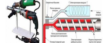
Machining sheet or profile metal when preparing parts or creating a workpiece often requires the removal of some material. Cutting a sheet, obtaining a separate part, adjusting it to the installation site - all this is required when creating products, in construction and in the home.
Such an operation is also possible at home; complex equipment is not required. Every business person knows what tool is used to perform the metal cutting operation.
Metal cutting - what is it?
Cutting consists of the planned and controlled formation of the required shape of a sheet metal part. The process is included in the list of standard plumbing operations, the level of complexity is low.
The bottom line: remove excess material according to the intended shape and size using just a couple of tools.
Metal cutting
Markings are applied to the blank sheet, and processing of blanks according to the established template is practiced.
Then, with a slight deviation from the line, the material is separated by striking the chisel with a hammer.
With careful actions, the quality of the part will be quite high.
The only need is subsequent processing of the edges: due to the impact method, the edges will look torn.
What is this operation used for?
- removing allowances and edges on the finished product;
- receipt of finished products and sheet blanks;
- removal of scale and other marketable defects;
- obtaining recesses (grooves, grooves, etc.).
Who needs this operation?
- workers of machine-building and repair organizations, foundries, in automobile repair shops - where work with metal takes place;
- in construction and repair (interior and exterior work);
- specialists involved in equipment repair;
- to ordinary people for household and household needs.
Equipment and tools used
This list depends on the method of work. Manual cutting is carried out using:
- cutting tools (chisels, crosspieces, etc.);
- a plumber's hammer (chosen by weight and handle length);
- vice;
- metal substrate;
- marking tool.
A metalworking chisel structurally consists of three main parts: impact, middle (holder) and cutting (working). The shape of the cutting part is different for each and depends on the task being solved. A chisel is used to perform a standard chopping operation. Kreuzmeisel has a narrower cutting edge. The groover is designed for cutting grooves, so its cutting part is made in the shape of a semicircle. The beard is made from a round metal rod, and has a working part in the shape of a circle sharpened around the perimeter. It is used to cut holes in sheet metal. All percussion instruments are made from durable tool steel.
The main parameters of these tools are geometric dimensions and sharpening angles of the cutting part. A plumber's hammer is used to strike the upper (impact) part of the chisel. They differ in the shape of the striker (round or square), the method of attaching the handle, and the total weight.
Cutting out small parts, holes, and individual parts is done using fastening equipment or on steel substrates. To ensure secure fastening, this operation is performed in a vice.
Various metalwork rulers, squares, marking calipers, and small markers are used as marking tools. To make marks, the following are used: cores (of various modifications), scribers with different tip shapes, and pencils. The tools used are manufactured according to developed standards
In industrial enterprises, the tools for cutting metal are special machines. These include:
- guillotines;
- presses (hydraulic and mechanical);
- press shears;
- angle cutting machines.
They have high productivity and allow you to cut even very thick metal.
The hydraulic guillotine is controlled by an electronic unit. With its help, the parameters of the future operation are set. Set the type of metal, the cutting angle, the amount of pressure on the knife, and the cutting speed. In addition to the guillotine, so-called combined units are used to solve these problems. These include cutting machines (press shears) and highly specialized ones (angle notching machines, presses and dies). Press shears are used for cutting sheets and strips of metal, shaped and long products. They work well with profile metal, for example, channel, I-roll, square. With their help, smooth holes and grooves of various shapes are obtained.
Angle notching machines allow angular cutting of metal products of almost any thickness. High precision cutting is achieved thanks to the presence of a scale that allows you to accurately lower the tool to the required place and a correctly sharpened set of chisels.
Presses and stamps solve similar problems. They use mechanical, hydraulic, pneumatic and electric drives.
What operations are performed when cutting metal?
When performing felling, you should remember the mandatory operations. All techniques used directly affect the productivity and quality of the result.
Metal transportation
Transportation of metal intended for processing is carried out manually or using mechanization. Trolley, stretcher, lifting and transport equipment up to a beam crane - depending on the weight and size characteristics.
Marking is carried out in sufficient lighting.
During the cutting process, it will not be superfluous to periodically check it if erasable products (pencil or chalk) were used.
All hand work is accompanied by body position and leg stance.
Sitting during the process is ineffective, as the impact force is reduced. By making small changes in body position, it is possible to vary the angle of impact and select the most effective position.
The exception is machine work. The Safety Instructions and Procedure contain the full scope of recommended actions. The regulations usually contain all the requirements and recommendations.
It is necessary to stand half a turn in relation to the place where the hand cut is performed.
The distance between the table and the body is approximately half the body or as convenient at a particular moment.
To apply sufficient force to the edge of the part to deform and cut it, it is optimal to hold it with a vice. The product should protrude from the jaws a couple of millimeters from the marking line - otherwise the required dimensions will not be met.
Holding the instrument is confident, all movements are precise and without undue haste.
For safety reasons and at the same time creating the most powerful blow, you need to hold the handle 1-2 cm from the end, and not near the head. Hold the chisel with 2-3 cm between your hand and the striking part.
Metal cutting operations
It is recommended to strike the chisel with a hammer in the center of the striking part. To maintain the greatest accuracy, when striking, you need to concentrate your gaze on the connection between the tip and the material. If you look at the striking part, there is a high risk of the cutting edge moving out of place.
Thick metal is processed in several approaches. It is recommended to alternate between deepening and removing metal from the groove. After this, subsequent cutting down along the resulting small thickness.
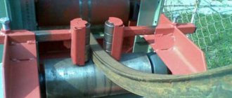
Cutting of closed profiles (round, square, rectangular or other pipe) is carried out with their uniform rotation. A blow is made with a cut of a certain length, the tube is rotated, and the cut is repeated. Only a small residual strip may be broken off, not the entire tube.
Manual
Manual cutting is a very simple and common process, well known to almost any car owner or home handyman who has at least once had to pick up a hammer and chisel in order to cut off an extra piece or, for example, a rusted screw.
Actually, a chisel and a hammer are the main tools. As for the hammer, a standard metalworking tool weighing 0.4-0.8 kilograms with a 35-45 centimeter handle is used for work.
A chisel is a carbide metal bar with a cutting edge at one end. The width of the working part, its shape and sharpening angle, as well as the total length of the tool may vary depending on its purpose. The most commonly used chisels are 2 and 2.5 centimeters wide with a flat or slightly rounded cutting edge.
An analogue of a chisel is a crossmeisel. Its main differences lie in the shape of the working part, most often drop-shaped, with a narrow cutting edge (no more than 1 centimeter), and application. While the chisel is used to cut through rolled sheets or separate parts of products, the crossmeisel is mainly used to form various grooves and grooves on the surface of the workpiece.
Additionally, you need to prepare a workplace. This could be a vice, an anvil, or a soft metal backing plate if you need to cut right through the sheet.
The cutting technique varies depending on the workpiece used and the desired result. There are:
- horizontal,
- vertical.
In the first case, the workpiece is clamped in a vice, and the chisel is set at an angle of 30-35 degrees relative to the plane of the table, that is, on the side of the metal product being processed. This, for example, allows you to cut off the excess part of the metal sheet protruding from the vice. The same is true for cross-cutting when it is necessary to cut a groove in the surface of a product. In this case, with each blow, the tip of the tool moves along the intended axis of the cut or groove.
Vertical cutting is used mainly with rolled sheets. With its help, you can cut off an extra piece of the plate or punch a hole of any shape. In this case, the chisel is installed strictly perpendicular to the plane only at the first and last blow, and the main part of the work is carried out with a slight tilt of the tool in the direction opposite to the movement. For greater convenience and accuracy, marking marks can be pre-applied to the sheet, specifying the position of the cutting edge.
Depending on the thickness of the material, work can be carried out on one side or on both sides, followed by separation of the piece by breaking or knocking out.
Working manually, it is almost impossible to ensure high accuracy and productivity, which is why the following methods are used in industry.
What are the methods for cutting metal?
Methods of achieving a goal can be classified according to a number of characteristics.
Goal:
- edge or surface cleaning;
- dividing the workpiece into parts of a simple shape (rectangles, triangles) or a little more complex (polyhedrons, rounded silhouettes);
- cutting down a complex configuration, which will require changing the cutting direction and a certain amount of time;
- removing a volume of metal to a specified depth and width.
Locksmith tools:
- manual type: hammers, chisels and other tools;
- mechanized type: a group of machines and structures with the help of which separation along the line is carried out with less labor and time.
Vector of movement of the working tool (affects the required force and the overall organization of work):
- vertical cutting (the cutting edge acts from above);
- horizontal (cutting is performed at an angle to the horizontal, the workpiece is fixed vertically).
Need for fixation:
- not required - just adjust by hand;
- minimal pressure - a heavy object will be required;
- reliable fixation - in a vice, clamps or clamps;
- when working on equipment - using integrated press beds.
The quality of the result directly depends on the means used. The type and condition of the tool (machine), the mechanical properties of the material and its thickness, the speed of work and the experience of the person - these factors are of great importance.
Possible defects
During this operation, certain defects always appear. The main defects include:
- the cut edge is not straight;
- The parallelism of both edges of the part is not maintained;
- the edge of the part turns out torn with burrs and great roughness.
Each of the defects that appear has its own individual causes. The first defect always appears with weak fixation of the workpiece. This defect is especially evident if the cutting process is carried out on a metal frame without fixing the part. The manifestation of these defects is caused by the following reasons:
- the part is not secured securely enough;
- the applied marking has shifted;
- the process was carried out with blows exceeding the necessary force;
To eliminate them, you need to follow simple rules:
- Check the strength of the workpiece;
- Maintain the accuracy of the location of the part relative to the applied marking;
- Check the sharpening parameters of the tool.
When cutting grooves, in addition to the listed defects, others may appear. These include:
- torn groove edges;
- the depth of the groove varies along the length;
- chips at the end of the groove;
To prevent the occurrence of the listed defects, it is necessary to follow the procedures established by the instructions for use of specific equipment and accepted standards. Before the operation, preparation is made for cutting the workpiece itself, the cutting tool and the machine used.
If you follow the rules for preparing and carrying out cutting and cutting operations, you get a smooth edge, without defects or chips.
What is called manual cutting of metal?
This plumbing business is not highly complex. It is advisable to pre-clamp the semi-finished product - this will ensure the stability of the part and eliminate vibrations. To do this, you will need a powerful base: a metal table, cabinet or frame with a vice. Ordinary furniture or improvised items will not work.
To create force and transfer it to the cut, you need a tool. The chopping technique is to provide a small indentation to ensure the installation of the tip and perform the main chopping blow.
The basic movement is called the “swing.” It depends on the required impact force and is performed with a movement based around one of the following joints:
- wrist - for light blows and precise manipulations;
- elbow – the main option, suitable for impact during steady-state operation with small and medium thicknesses;
- shoulder - for the most powerful blow when working with large thicknesses or serious scale.
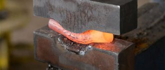
Chopping metal
The impact increases as the weight of the hammer and the length of its handle increase. The heavier the impact tool, the greater the impact on the cutting edge. This way you can get an accurate and fairly clean cut.
With a strong impact, there is immediately a very high probability of the cutting edge coming off and damaging the material. There are frequent cases of instrument damage and even injury. Therefore, haste and inattention are not welcome.
The manual cutting method is optimal for single production and home conditions. It is good for its versatility, but has a number of disadvantages:
- not the highest performance;
- need for time reserve;
- the result in most cases will require modification of the edge (removal of a thin layer, grinding).
General purpose working and auxiliary tools
Steel hammers . The size of the hammer is determined by its mass (weight).
For light work, hammers (H=80 mm) weighing 100–200 g are used; for normal work and various plumbing operations (H=100 mm) - 300–500 g; for repair work (120 mm) - 600–800 g (Fig. 3).
Hammers with a round striker are used in cases where significant force or accuracy of impact is required. Square-faced hammers are chosen for lighter jobs.
Rice. 3. Hammer
Hammers are made from steel grades 50, 40X or U7.
The working parts of the hammer are hardened and tempered; The hardness of these parts should be 43–51 HRC. The hammers should be free of cracks, films, hairs, cracks and other defects.
The length of the handle L depends on the mass (weight) of the hammer. For light hammers (up to 200 g) it is 250–300 mm, and for hammers of medium weight (400–600 g) the average length of the handle is taken to be 350 mm. The handle should have an oval cross-section with a ratio of major to minor diameters of 1.5:1. The surface of the handle should be smooth and clean. After placing the hammer on the handle, its end is wedged with wooden or metal wedges with a thickness of 1 to 3 mm. A notch (ruff) is made on the sides of the metal wedges to prevent the wedge from jumping out of the handle. Wedges are usually placed along the major axis of the handle section, less often along the minor axis.
The materials for hammer handles are dogwood, rowan, maple, hornbeam, birch, i.e. tree species characterized by strength and elasticity. Wood moisture content should not be higher than 12%. There should be no knots or cracks on the handles.
Device for chopping metal - guillotine
Cutting steels and softer alloys may be required constantly and in large quantities. In production conditions, home workshops and small private workshops, machines and devices with varying degrees of mechanization are used:
- manual guillotine - a frame-type structure based on a long carbide knife;
- press shears - a guillotine driven by an electric or pneumatic drive;
- press - a more detailed unit, manufactured in the form of full-fledged equipment;
- die-cutting machine - allows you to process a sheet of metal and obtain holes in it of the required shape and density.
The guillotine is designed relatively simply. A supporting frame is installed on the foundation, on which the remaining components are mounted. The housing, knives, drive, pipelines (cable routes) and controls create the technical ability to cut sheet metal and other rolled products, for example, a channel or angle. The unit is completed with protective fences and alarm systems.
Manual guillotine
The guillotine is interesting due to its range of adjustable parameters:
- type of metal and its mechanical characteristics (processing of aluminum alloy and alloy steel will require different forces);
- optimal angle α, “alpha” (characteristic of the relative position of the rear edge of the tool and the surface being cut);
Guillotine diagram
- knife feed speed;
- working pressure created by the knife.
The adjustment is carried out by mechanical or electronic components.
Press shears
The main advantage of mechanized equipment is high efficiency and the ability to work with large thicknesses. Mechanized industrial equipment is characterized by both flexibility in use and high specialization:
- cutting sheet metal of any thickness depending on the capacity of the installation;
- creating unique corner cuts;
- development of openings in long and shaped steel;
- obtaining highly specialized objects (for example, grooves in bearing liners and bushings - in addition to cutting, chopping is also involved here).
Chopping, cutting and filing during metalwork work
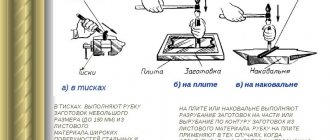
Chopping is a metalworking operation, during which a layer of metal is either removed from the surface of the workpiece with the help of a chisel and a plumber's hammer, or the workpiece is cut into pieces. Felling is used in cases where machine processing is irrational or difficult to perform.
Felling, as a rule, is a preparatory operation. The accuracy of processing using cutting does not exceed ±0.5 mm. The cutting is carried out in a vice. Sheet material blanks are cut into pieces on a stove. When cutting workpieces made of viscous metals, the working edge of the chisel should be moistened with industrial oil. Blanks made of brittle metals (cast iron, bronze) are cut from the edge to the middle.
To make cutting of wide surfaces easier and faster, grooves are first cut with a cross-cut tool, and then the remaining metal between the grooves is cut off with a chisel. Thick pieces are cut on both sides and then broken.
The impact tools for chopping are hand-held, pneumatic or electric hammers, and the cutting tools are chisels, cross-cutters, bits, and drifts. The productivity of mechanized cutting increases 4–5 times compared to manual cutting. When choosing a mechanic's hammer, the width of the chisel blade is taken into account: for 1 mm of the width of the chisel blade there should be 30...40 g of hammer mass, and for a cross-cutting hammer - 80 g. The sharpening angles of chisels and cross-cuttings should be as follows, °:
Cast iron, hard steel, bronze - 70
Soft and medium hard steel - 60
Brass, copper, titanium alloys - 45
Aluminum alloys - 35
At the installation site, when installing equipment on foundations, concrete surfaces of foundations and metal surfaces of linings are cut after gas cutting.
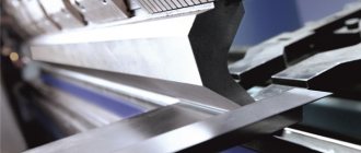
Cutting is a metalworking operation of separating blanks of sheet and profile material and pipes into parts. Depending on the size, shape and material of the workpieces, cutting is carried out using hand or mechanized tools: scissors, needle-nose pliers, hand saws, pipe cutters. There is a distinction between metal cutting with and without chip removal.
Hand scissors are used to cut workpieces made of thin sheet and strip material (0.5...1.0 mm thick from steel and up to 1.5 mm thick from non-ferrous metals). For cutting along a straight line and a large radius circle, scissors with straight blades are used, and for cutting shaped profiles with small radii, scissors with curved blades are used.
The cutting edges of the scissors move relative to each other gradually. The edges of the scissors in the articulated joint should fit snugly against each other and move easily. With a tight move, a lot of friction occurs, causing excessive effort in work and rapid wear of the cutting edges. If there is a large gap between the cutting edges, the material being cut will wrinkle and jam. The scissors are held in the right hand, covering the handles with four fingers and pressing them to the palm, the little finger is placed between the handles of the scissors. Holding the sheet with your left hand, feed it between the cutting edges, guiding the upper blade exactly in the middle of the marking line, which should be visible when cutting.
When cutting in a straight line, you should use left-handed scissors and measure their opening to such an extent that they can grip the sheet to a length of no more than 30 mm along the straight line. When cutting along external figured contours, the sheet is turned so that the scissors do not cover the cutting line.
Workpieces are also cut with hand scissors with one handle clamped in a vice. This technique is used when cutting workpieces up to 1.2 mm thick in a straight line. Lever shears are used for cutting workpieces made of sheet material up to 2.0 mm thick. Needle nose pliers (end cutters) are used to cut wire with a diameter of up to 5 mm. Before cutting, it is straightened by pulling it around a round mandrel. The wire is placed between the blades so that it is perpendicular to them. The sharpening angle of the cutting edges is selected depending on the hardness of the material being cut; usually it is 55...60°.
Hand saws are used for cutting thick sheets, profiles and pipes. Using a hand hacksaw, slots and grooves are cut, and the workpieces are trimmed and cut along the contour. The workpiece is clamped in a bench vice and marked; if necessary, use a triangular file to make a cut along the notch and perform the cutting. The pipes are clamped in a special pipe clamp mounted on a workbench. The cutting location should be as close to the clamp as possible.
To cut, a hand saw must be properly secured and have good coordination of movements. Movements when working with a hacksaw should be smooth, without jerking and with such a scope that all the teeth of the blade are involved in cutting. The speed of movement when cutting with a hacksaw should be 30...60 strokes per minute.
When finishing cutting, you should ease the pressure on the hacksaw and reduce the speed of movement to avoid breaking the blade. Hand saw blades with a pitch of 0.8...1.0 mm are used for cutting thin-walled pipes and sheet material; in increments of 1.25 mm - for cutting profiles; in increments of 1.6 mm - in all other cutting cases. Before work, the blade is lubricated with thick lubricant or industrial oil.
To cut pipes, in addition to a hand hacksaw, a manual pipe cutter is used, in which the cutting parts are steel disc rollers. The pipe is clamped in a clamp, put on a pipe cutter and, by rotating the pipe cutter handle around its axis, the movable roller of the pipe cutter is brought into contact with the pipe wall. Using the handle, turn the pipe cutter around the pipe one turn, check the alignment of the markings and the cut line, then rotate the pipe cutter around the pipe until its walls are cut.
For large volumes of cutting sheet material along straight and shaped profiles with a sheet thickness of 2.5...4.8 mm, manual pneumatic and electric scissors are used. There are knife and slotted scissors. In knife scissors, one knife is movable, the other is stationary, and in slotted scissors, the material is sequentially cut through a punch.
Filing is a metalworking operation in which a layer of material is removed from the surface of a workpiece using a file or needle file. By filing, the parts are given the required shape and size, and the mating surfaces are adjusted in place. There is a distinction between coarse filing, when a layer of metal up to 1.0 mm thick is removed, and fine filing, when the layer of metal being removed does not exceed 0.3 mm. Filing is used to process flat and curved surfaces, grooves, grooves, holes of various shapes, etc. The accuracy achieved when filing with various types of files is given in table. 3.
A file is a multi-edged cutting tool. Based on the number of teeth per 1 cm of length, files are distinguished into six numbers: 0; 1 - pugnacious; 2; 3 - personal; 4 and 5 - velvet. Brushed files are used for rough filing, velvet files are used for finishing the surface.
When filing, the workpiece is clamped in a vice so that the surface to be filed protrudes above the level of the jaws by 8...10 mm. To protect the workpiece from dents when clamping, jaws made of soft material are put on the jaws of the vice. Filing begins with checking the processing allowance, which should ensure the manufacture of the part according to the dimensions indicated in the drawing. Depending on the requirements for surface roughness parameters, filing is carried out with a brute, personal or velvet file. To obtain a correctly sawn straight surface, filing is carried out in cross directions at an angle of 30...40° to the sides of the workpiece.
The file should not be brought to the corners of the workpiece, since the file support area is reduced, a large layer of metal is removed - a “blockage” of the edge of the processed surface is formed. The formation of blockages is promoted by bending of the workpiece. Deviation from the flatness of the surface is checked with a measuring ruler against the light, applying it in different directions. To improve filing conditions, eliminate blockages, etc. special devices are used: filing prisms, universal bastings, jigs.
When processing flat surfaces located at an angle of 90°, first the surface taken as the base is filed, then the surface perpendicular to the base. Control is carried out at the inner corner of the square.
Convex curved surfaces are processed by rocking the file: at the beginning of the file movement, its toe touches the workpiece and the handle is lowered; as the file advances, the toe lowers and the handle rises; during the reverse stroke, the movements of the file are opposite.
Table 3. Achievable accuracy (mm) when filing
File cut number | Metal layer thickness, filmed in one movement, mm | Average deviations | ||
| from straightness or flatness | from given size | |||
| 0;1 | 0,05…0,1 | 0,15…0,2 | 0,2..0,3 | |
| 2;3 | 0,02…0,06 | 0,03…0,06 | 0,05…0,1 | |
| 4;5 | — | 0,01…0,02 | 0,02…0,05 | |
Concave curved surfaces, depending on the radius of curvature, are processed with round or semicircular files. The file makes a complex movement - forward and to the side with rotation around its axis. Sawing holes of various shapes begins with markings and is carried out with files of the appropriate configuration.
One of the main conditions for high-quality processing is the correct choice of files. They are selected according to the cross-sectional profile depending on the shape of the hole being machined: for square holes - square; for rectangular holes - flat and square; for triangular holes - triangular, rhombic and semicircular; for hexagonal holes - triangular and square. Files must have a working part width of no more than 0.6...0.7 side size or hole diameter; The length of the file is determined by the size of the surface to be filed plus 200 mm.
To process holes with curved contours, round and semicircular files are used, whose radius of curvature is less than the radius of curvature of the surface being processed. Needle files are designed for processing hard-to-reach and narrow places. Control is carried out with calipers or special templates.
The mutual fit by filing of two parts that fit together without a gap with great accuracy is called fitting. Fitting is performed as a final operation when processing parts of hinged joints and, most often, when making various templates. For fitting, files and needle files with a fine notch are used.
Files and needle files are cleaned of shavings with a steel brush, and heavily contaminated ones are immersed in a 10% sulfuric acid solution for 10...12 minutes, then washed in water and cleaned with a steel brush. The durability of general-purpose metalworker's files when filing steel workpieces is on average 100 hours, and 140 hours when filing non-ferrous metal workpieces.
868
What is the essence of metal cutting?
Regardless of the equipment used, the entire cutting process comes down to the following.
The workpiece must be marked - apply the shape of the element to be cut, taking into account the dimensions and tolerances for the thickness of the cut. The latter is often forgotten - meanwhile, for cutting metal, you should plan a cut from one thickness of the workpiece.
When marking, it is important to use the maximum usable area - for this, preliminary planning of placement is optimal. This is especially true for products with complex shapes, and the trajectory of their cutting may be limited in direction and angles.
When cutting metal, the first task is to secure the material. This is done using a vice or other clamping device. An ordinary anvil or just a massive piece of metal is popular for this.
Metal cutting
If the work is carried out by mechanization, further operations are reduced to moving the workpiece relative to the lowering knife. When manually cutting, cutting will require at least 2 steps:
- Initially, weak blows are made along the intended line - this is required to establish the cutting contour;
- When the entire line or a separate part of it is ready (if the trajectory is complex), cutting is carried out - powerful blows are applied to the cutting tool.
As a result of this, the cutting edge passes exactly along the desired line of cutting off the excess. Without preliminary marking, the movement of the tip will be difficult, and there is a risk of it reaching the body of the future part.
When the work is done on one side, the sheet is turned over, the process is repeated for the reverse side. With a material thickness of more than 2-3 mm, this is almost guaranteed to be required. If you cut the entire thickness at once, the quality of the edge will be unsatisfactory.
Metal cutting
As a result of the described sequences, metal is gradually removed around the perimeter, and the shape of the part is revealed. In this case, safety is of great importance: individual pieces of material can fly off at high speed.
To prevent injury you must:
- put on locksmith glasses and gloves before starting work;
- try to knock the metal in such a direction that its parts do not fall on people;
- organize the absence of strangers in the work area, for which the use of screens is allowed;
- blows with a hammer - apply without excessive force, try not to hit the vice.
All working tools must be kept intact and in order.
If the work is done without a vice (“horizontal” method), the essence does not change:
- the workpiece is laid flat, it can be pressed so that the cutting line is free (with a heavy object, a clamp);
- the chisel is pre-sharpened until the required degree of sharpness and curvature is obtained;
- felling is carried out in 2 stages (preparatory-basting and power), with a continuous line in one direction;
- When bending the workpiece, if this interferes, its flatness is periodically restored (with hammer blows).
Chopping and cutting metal
BASICS OF METAL WORKING
Basic concepts of the theory of basing, straightening and marking
1.1.1 Theory of workpiece basing. Base - a surface, line, point that determines the position of a part in a unit during processing or control. There are design, technological and measuring bases.
Design bases - are assigned during design and determine the connecting dimensions in the assembly.
Technological bases - determine the position of the part (workpiece) in the machine relative to the headstocks, spindles, and cutting tools. Dimensions are measured from them when making parts.
Measuring bases - determine the position of the surfaces of parts relative to the measuring tool.
It is desirable that the design and technological bases coincide. For processed parts, the most processed surface is taken as the technological base; for cylindrical workpieces or workpieces with holes - a flat surface parallel to the axis of the surface or the axis of the holes; for unprocessed workpieces - one of the outer surfaces.
1.1.2 Editing is an operation intended to eliminate distortions in the shape of workpieces (dents, bulging, waviness, warping, curvature, etc.).
Straightening is performed on both cold and hot metal. Editing is done manually (on a steel or cast iron plate or on an anvil); on the right presses or in the right rollers. For manual straightening, hammers made of soft materials (copper, lead, hardwood) with a round polished striker or smoothers and supports (bars) are used. For hardened workpieces, hammers with a hardened shaped head are used.
The curvature of the workpieces is checked by eye, by the gap between the leveling plate and the workpiece laid on it. Bent areas are marked with chalk.
Editing raw material:
a) straightening a strip curved along a plane - strong blows are applied to the most convex places with a hammer or sledgehammer. As it straightens, the impact force is reduced, the workpiece is periodically turned over;
b) straightening a steel strip bent on an edge - the workpiece is laid on a plate, dividing along the length into approximately equal width zones of curvature. The blows are applied in rows from the center to the edges, starting from the most concave part, the force of the blows decreases from the most curved part to the less curved (see Fig. 1.2,a );
c) straightening of twisted strips - carried out using the unwinding method; one end of the workpiece is clamped in a metalworker's (stationary) vice, the other - in a manual one, unwinding is carried out with a lever inserted into a special one. hand vise hole;
d) straightening sheet material - chalk out convex and wavy places; then blows are applied according to the pattern (see Fig. 1.2, b ), from the edge to the center the force of the blows
decreases; During editing, the sheet is turned over in a horizontal plane so that the blows are distributed in a circle over the entire area. If the sheet has waviness, then it is corrected first; the leaf in the middle stretches out and the waviness disappears.
a – steel strip; b – sheet material; c – hardened square
Figure 1.2 Material straightening schemes
e) straightening of thin sheets - carried out with a wooden hammer (a mallet0 or using a textolite gasket, which is placed on convex places; they hit the defects with a hammer; foil materials are placed on a flat surface and ironed with smoothers - smooth plates with rounded edges;
f) straightening of hardened material - carried out with a bench or straightening hammer with an elongated or rounded head. The strip is placed with the convex side down, the blows are frequent but not strong. Complex details are corrected along the distortion contour, for example, corners. The pattern of striking, their strength and direction are shown in Fig. 1.3, c.
1.1.3 Marking. Preparing materials for work. Prepare the surface for marking in the following sequence.
1 Preparation of dyes. To paint untreated surfaces (castings, forgings, rolled products), a chalk solution is used (ground chalk is diluted in water). To protect the paint layer from abrasion and for its quick drying, wood glue is added to the dye composition (600 g of chalk and 50 g of wood glue per 4 liters of water).
Cleanly processed surfaces of products are painted with a solution of copper sulfate (two to three teaspoons of copper sulfate crystals per glass of water) or a special varnish for marking.
2 Preparing the workpiece for painting. When preparing workpieces for painting, they are cleaned of dust, dirt, scale and rust with a steel brush. The plates must not have burrs or sharp corners. One plate is cleaned on both sides with sandpaper, and the planes of the remaining plates are left untreated.
3 Painting surfaces. When applying the dye, the workpiece is held in the left hand in an inclined position.
Figure 1.3 techniques for painting surfaces before marking
A thin and uniform layer of dye is applied to the plane with cross vertical and horizontal movements of the brush. The solution should be applied only with the end of the brush in small quantities to avoid the formation of smudges. Cleaned surfaces are painted with vitriol solution, and untreated surfaces are painted with chalk solution. After finishing painting, the plates must be dried.
4 Marking - applying marking lines (marks) to the surface being processed, which show the boundaries of processing the workpiece. There are flat and spatial markings. (The difference is your own).
a – scriber; b – double gauge; c – height gauge; g – center punch;
d – marking line before processing; e – marking line after processing
Figure 1.4 Tools for marking work
When marking, three types of tools are used (see Figure 1.4, a - d ):
a) for applying and marking marks - scribers, single or double thickness gauges, height gauges, marking compasses, center punches;
b) to find the centers of circles (holes) - center punch, center finder, etc.;
c) devices for marking - spacers, jacks, rotating devices, vertical posts, dividing heads, center headstocks, etc.
Marking is done on special marking plates made of gray cast iron. The upper working plane and side surfaces of the slab must be scraped, dry and clean. At the end of the work, wipe the stove with dry rags, lubricate it and cover it with a wooden lid; metal dust and shavings are removed with a brush and into a dustpan. There should be a special trash box nearby.
The workpiece must not be moved across the slab to avoid the formation of scratches and nicks. The slab is placed on a stable foundation in a lighted place. General vertical and local lighting of the workplace is provided.
Before work, clean the workpiece with a steel brush and sandpaper to remove corrosion, scale, etc. Before marking, it is necessary to study the drawing of the part, compare the dimensions of the workpiece with the actual dimensions of the part, and determine the technological bases. After this, the types and sequence of marking operations are determined.
Planar marking techniques. First, all the horizontal lines and marks are drawn, then all the vertical ones, then the inclined ones. The last to be drawn are circles, arcs and mates. If center risks are chosen as the technological base, then marking begins with them. The marking is complete if the image on the plane completely corresponds to the drawing of the part.
Straight lines are drawn with a scriber tilted away from the ruler. The ruler or square is pressed tightly against the workpiece, the line is drawn once, without interrupting the movement of the hand. If the line (risk) does not work out, it is painted over and drawn again. The division of a circle into equal parts is carried out using geometric constructions or using special tables. To mark a batch of identical parts, templates are used that are made from sheet steel. The configuration and dimensions of the template must exactly match the part drawing.
Spatial marking techniques. The difficulty of spatial marking lies in the need to link the markings of various surfaces with each other.
As a technological base, a surface is selected relative to which the largest number of axes or planes can be marked, and
the main axes of the workpiece, the number of its positions on the plate and the sequence of markings.
The workpiece is placed firmly, without swinging, on the marking plate so that each axis or plane of the part is perpendicular to the general plane of the plate. To install and align the workpiece, prisms, support pads, jacks, marking cubes and special devices (for example, rotating) are used. The first installation is carried out so that it is convenient to start marking from the selected technological base.