UNC type
The large unified thread of the ASME 1 1 standard has the UNC code. Dimensions interchangeable with previously used NC threads.
| Designation | DN (mm) | DN() | Step | Turns per inch | Dst |
| N1-64 UNC | 1,854 | 0,073 | 0,397 | 64 | 1,5 |
| N2-56 UNC | 2,184 | 0,086 | 0,453 | 56 | 1,8 |
| N3-48 UNC | 2,515 | 0,099 | 0,529 | 48 | 2,1 |
| N4-40 UNC | 2,845 | 0,112 | 0,635 | 40 | 2,35 |
| N5-40 UNC | 3,175 | 0,125 | 2,65 | ||
| N6-32 UNC | 3,505 | 0,138 | 0,794 | 32 | 2,85 |
| N8-32 UNC | 4,166 | 0,164 | 3,5 | ||
| N10-24 UNC | 4,826 | 0,19 | 1,058 | 24 | 4 |
| N12-24 UNC | 5,486 | 0,216 | 4,65 | ||
| ¼”-20 UNC | 6,35 | 0,25 | 1,27 | 20 | 5,35 |
| 5/16”-18 UNC | 7,938 | 0,313 | 1,411 | 18 | 6,8 |
| 3/8”-16 UNC | 9,525 | 0,375 | 1,587 | 16 | 8,25 |
| 7/16”-14 UNC | 11,112 | 0,438 | 1,814 | 14 | 9,65 |
| ½”-13 UNC | 12,7 | 0,5 | 1,954 | 13 | 11,15 |
| 9/16”-12 UNC | 14,288 | 0,563 | 2,117 | 12 | 12,6 |
| 5/8”-11 UNC | 15,875 | 0,625 | 2,309 | 11 | 14,05 |
| ¾”-10 UNC | 19,05 | 0,75 | 2,54 | 10 | 17 |
| 7/8”-9 UNC | 22,225 | 0,875 | 2,822 | 9 | 20 |
| 1”-8 UNC | 25,4 | 1 | 3,175 | 8 | 22,25 |
| 1 1/8”-7 UNC | 28,575 | 1,125 | 3,628 | 7 | 25,65 |
| 1 ¼”-7 UNC | 31,75 | 1,25 | 28,85 | ||
| 1 3/8”-6 UNC | 34,925 | 1,375 | 4,233 | 6 | 31,55 |
| 1 ½”-6 UNC | 38,1 | 1,5 | 34,7 | ||
| 1 ¾”-5 UNC | 44,45 | 1,75 | 5,08 | 5 | 40,4 |
| 2”-4 1/2 UNC | 50,8 | 2 | 5,644 | 4,5 | 46,3 |
| 2 ¼”-4 1/2 UNC | 57,15 | 2,25 | 52,65 | ||
| 2 ½”-4 UNC | 63,5 | 2,5 | 6,35 | 4 | 58,5 |
| 2 ¾”-4 UNC | 69,85 | 2,75 | 64,75 | ||
| 3”-4 UNC | 76,2 | 3 | 71,7 | ||
| 3 ¼”-4 UNC | 82,55 | 3,25 | 77,45 | ||
| 3 ½”-4 UNC | 88,9 | 3,5 | 83,8 | ||
| 3 ¾”-4 UNC | 95,25 | 3,75 | 90,15 | ||
| 4”-4 UNC | 101,6 | 4 | 96,5 |
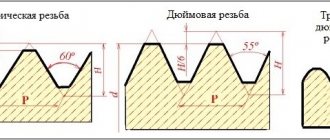
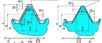
Features of the ANSI ASME B 1 1 UNS thread profile are a 60° isosceles triangle in section and cut tips.
Large threads are characterized by high resistance to jamming and breaking of its turns. Therefore, UNS is considered a threaded profile of general use for all branches of mechanical engineering and construction.
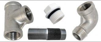
Pipe thread
A separate standard group that regulates the connection of pipes using different wall materials. Inch pipe threads are divided into types:
- cylindrical type;
- conical view;
- NPSM thread.
Straight pipe thread
Also known as Whitward carving. It is used for cylindrical connections using threads and for joining a cylindrical internal thread with an external conical pipe.
The designation of the shape profile is an inch thread with a profile in the form of a triangle with equal hips and an angle at the top of 55º. It is allowed to connect pipes with a maximum diameter of 6 inches, and for pipes larger than an inch size, a connection by welding is used.
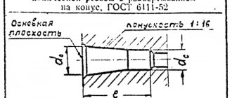
Tapered inch pipe thread
It is cut on the surface of pipes for conical connection of pipes and for connecting cylindrical threads on the inside and tapered threads on the outside. The use of sealed gaskets is mandatory; the sealing role is partially played by the thread. The profile is designated as an inch type with a taper; the letter expression of the index indicates its location. R indicates external thread, Rc indicates internal thread, and the letters LH are used for left-hand threads.
Thread profile type NPSM
This thread cutting is done in accordance with American pipe thread standards and is similar in location and type to cylindrical inch threads. Defined by a profile shape in the form of a triangle with an apex of 60º and is produced in sizes from 1/16 to 24 inches.
This type should not be confused with the American subtype NPT, which is a standard inch-threaded conical connection for pipes with increased reliability requirements when working with high pressure and in difficult operating conditions.
Differences between pipe and metric threads
There are not many of them; the most noticeable indicator that distinguishes one type from another is the shape of the threaded ridge cutting profile. In appearance it seems sharper, its apex angle is 55º.
In addition to the profile shape, the difference between metric cutting and the inch pipe version is the measuring parameters of pitch and diameter. Metric threads are measured in millimeters, while imperial threads are measured in inches. But to express metric indicators in inches, a non-standard value of 2.54 cm is used, and a special pipe inch equal to 3.324 cm.
A detailed table indicating the corresponding conversions from inches to millimeters can be found in the specified GOST. In addition to whole inch values, fractional values are also indicated. In addition, the pitch is not counted in millimeters, but in threads, indicating cut grooves on a measured inch segment.
The step is determined using working tools:
- combs;
- calibers;
- mechanical meters.
Measurements are made according to the same rules in metric and inch cutting. To begin with, we use a coupling or fitting with a cut external or internal thread, starting from known parameters. Screw the bolt into the thread and determine the tightness of the fit. If the bolt fits tightly, then the pitch and diameter are considered certain. If the bolt does not match, then try using a bolt of a different caliber.
It is more convenient to use a thread gauge, then the work happens faster - just attach the plate to the thread. The number of the thread is indicated on the tool plate, which is considered defined if the profiles match. A caliper or micrometer is used only to determine the outer and inner diameters.
Type UNEF
The special extra fine thread ANSI ASME B 1 1 for special applications is called UNEF. The dimensions of threaded connections are presented in the table below:
| Standard size | Step | Turns per inch | D drilling | D outer (mm) | D outer (inch) |
| N 12-32 UNEF | 0,794 | 32 | 4,8 | 5,486 | 0,216 |
| 1/4” –32 UNEF | 0,794 | 32 | 5,7 | 6,35 | 0,25 |
| 5/16” – 32 UNEF | 0,794 | 32 | 7,25 | 7,938 | 0,313 |
| 3/8” – 32 UNEF | 0,794 | 32 | 8,85 | 9,525 | 0,375 |
| 7/16” – 28 UNEF | 0,907 | 28 | 10,35 | 11,112 | 0,438 |
| ½” – 28 UNEF | 0,907 | 28 | 11,8 | 12,7 | 0,5 |
| 9/16” – 24 UNEF | 1,058 | 24 | 13,4 | 14,288 | 0,563 |
| 5/8” – 24 UNEF | 1,058 | 24 | 15 | 15,875 | 0,625 |
| 11/16” – 24 UNEF | 1,058 | 24 | 16,6 | 17,462 | 0,688 |
| ¾” – 20 UNEF | 1,27 | 20 | 18 | 19,05 | 0,75 |
| 13/16” – 20 UNEF | 1,27 | 20 | 19,6 | 20,638 | 0,813 |
| 7/8” – 20 UNEF | 1,27 | 20 | 21,15 | 22,225 | 0,875 |
| 15/16” – 20 UNEF | 1,27 | 20 | 22,7 | 23,812 | 0,938 |
| 1” – 20 UNEF | 1.27 | 20 | 24,3 | 25,4 | 1 |
| 1 1/16” – 18 UNEF | 1.411 | 18 | 25,8 | 26,988 | 1,063 |
| 1 1/8” – 18 UNEF | 1.411 | 18 | 27,35 | 28,575 | 1,125 |
| 1 ¼” – 18 UNEF | 1.411 | 18 | 30,55 | 31,75 | 1,25 |
| 1 5/16” – 18 UNEF | 1.411 | 18 | 32,1 | 33,338 | 1,313 |
| 1 3/8” – 18 UNEF | 1.411 | 18 | 33,7 | 34,925 | 1,375 |
| 1 7/16” – 18 UNEF | 1.411 | 18 | 35,3 | 36,512 | 1,438 |
| 1 ½” –18 UNEF | 1.411 | 18 | 36,9 | 38,1 | 1,5 |
| 1 9/16” – 18 UNEF | 1.411 | 18 | 38,55 | 39,688 | 1,563 |
| 1 5/8” – 18 UNEF | 1.411 | 18 | 40,1 | 41,275 | 1,625 |
| 1 11/16” – 18 UNEF | 1.411 | 18 | 41,6 | 42,862 | 1,688 |
The profile is similar to the previous case, all ANSI B 1 1 tables can be downloaded in PDF here. UNEF type threaded connections are used in precision engineering, instrument making, aviation, and shipbuilding.
Basic rules for slicing
- To correctly cut inch or metric threads, you must adhere to the following recommendations:
- Accurately select a drill of the required diameter. The hole diameters for UNF and UNC threads are shown in the tables above.
- Drill a hole strictly at right angles to the plane.
- Carry out cutting in a reciprocating motion. After two forward revolutions, make a backward revolution to remove chips.
- If there are two or three taps in the set, pass strictly by numbers - first with the first draft number, then with the second.
- It is advisable to use a lubricant to reduce friction.
Type UNF
The third table of ASME B 1 1 2003 in Russian shows the dimensions of fine unified threads for general use UNF:
| Standard size | Pitch (mm) | Turns per inch | Drilling D (mm) | D outer (mm) | D outer (inch) |
| N 0-80 UNF | 0,317 | 80 | 1,25 | 1,524 | 0,06 |
| N 1-72 UNF | 0,353 | 72 | 1,55 | 1,854 | 0,073 |
| N 2-64 UNF | 0,397 | 64 | 1,9 | 2,184 | 0,068 |
| N 3-56 UNF | 0,453 | 56 | 2,15 | 2,515 | 0,099 |
| N 4-48 UNF | 0,529 | 48 | 2,4 | 2,845 | 0,112 |
| N 5-44 UNF | 0,577 | 44 | 2,7 | 3,175 | 0,125 |
| N 6-40 UNF | 0,635 | 40 | 2,95 | 3,505 | 0,138 |
| N 8-36 UNF | 0,705 | 36 | 3,5 | 4,166 | 0,164 |
| N 10-32 UNF | 0,794 | 32 | 4,1 | 4,826 | 0,19 |
| N 12-28 UNF | 0,907 | 28 | 4,7 | 5,486 | 0,216 |
| ¼”-28 UNF | 0,907 | 28 | 5,5 | 6,35 | 0,25 |
| 5/16”-24 UNF | 1,058 | 24 | 6,9 | 7,938 | 0,313 |
| 3/8”-24 UNF | 1,058 | 24 | 8,5 | 9,525 | 0,375 |
| 7/16”-20 UNF | 1,27 | 20 | 9,9 | 11,112 | 0,438 |
| ½”-20 UNF | 1,27 | 20 | 11,5 | 12,7 | 0,5 |
| 9/16”-18 UNF | 1,411 | 18 | 12,9 | 14,288 | 0,563 |
| 5/8”-18 UNF | 1,411 | 18 | 14,5 | 15,875 | 0,625 |
| ¾”-16 UNF | 1,587 | 16 | 17,5 | 19,05 | 0,75 |
| 7/8”-14 UNF | 1,814 | 14 | 20,4 | 22,225 | 0,875 |
| 1”-12 UNF | 2,117 | 12 | 23,25 | 25,4 | 1 |
| 1 1/8”-12 UNF | 2,117 | 12 | 26,5 | 28,575 | 1,125 |
| 1 ¼”-12 UNF | 2,117 | 12 | 29,5 | 31,75 | 1,25 |
| 1 3/8”-12 UNF | 2,117 | 12 | 32,75 | 34,925 | 1,375 |
| 1 ½”-12 UNF | 2,117 | 12 | 36 | 38,1 | 1,5 |
An analogue of the UNF thread exists in the UK, and is abbreviated BSW. Fine cylindrical inch thread ensures high connection strength and precise adjustment of the relative position of the parts. Therefore, UNF is often called an adjustment thread, and is used on machine nuts/bolts, threaded adapters, adapter valves, and pipe fittings.
Marking
The designation of the thread in question includes a letter indicating the type (UNC) and a digital index indicating the diameter (in inches). In some cases, additional notations are used. They can reflect step (via a dash) and direction. For small options (less than 1/4''), special markings are used. This is due to their difficulty in measuring. Designations include numbers (from 0 to 12) and the frequency of turns (through a dash). For example, you can consider 1/4” – 20UNСх2 1/2”.
- 1/4 – diameter (in this case, the outer value is 6.35 mm, the inner value is 5.35 mm).
- 20 – frequency of turns.
- UNC - typ.
- 2 1/2'' is the length of the bolt.
Type 8 TPI
Fine unified thread 8 TPI according to ASME B 1 1 specification is developed for special applications, for example, critical parts of wood/metal lathes. The size range corresponds to the following values:
| Standard size | Pitch (mm) | Turns per inch | Drilling D (mm) | D outer (mm) | D outer (inch) |
| 1 1/16”-8 UN | 3,175 | 8 | 23,9 | 26,988 | 1,063 |
| 1 1/8”-8 UN | 3,175 | 8 | 25,5 | 28,575 | 1,125 |
| 1 3/16”-8 UN | 3,175 | 8 | 27,1 | 30,162 | 1,187 |
| 1 1/4”-8 UN | 3,175 | 8 | 28,75 | 31,175 | 1,25 |
| 1 5/16”-8 UN | 3,175 | 8 | 30,3 | 33,338 | 1,313 |
| 1 3/8”-8 UN | 3,175 | 8 | 31,75 | 34,925 | 1,375 |
| 1 1/2”-8 UN | 3,175 | 8 | 35 | 38,1 | 1,5 |
| 1 5/8”-8 UN | 3,175 | 8 | 38 | 41,275 | 1,625 |
| 1 3/4”-8 UN | 3,175 | 8 | 41,5 | 44,45 | 1,75 |
| 1 7/8”-8 UN | 3,175 | 8 | 44,5 | 47,625 | 1,875 |
| 2”-8 UN | 3,175 | 8 | 47,75 | 50,8 | 2 |
| 2 1/8”-8 UN | 3,175 | 8 | 50,9 | 53,975 | 2,125 |
| 2 1/4”-8 UN | 3,175 | 8 | 54 | 57,15 | 2,25 |
| 2 3/8”-8 UN | 3,175 | 8 | 57,2 | 60,325 | 2,375 |
| 2 1/2”-8 UN | 3,175 | 8 | 60,4 | 63,5 | 2,5 |
Weapon parts and fasteners for passenger cars from assembly lines in the USA and Canada often have this thread.
Accuracy classes and marking rules
A thread belonging to the inch type, as indicated by GOST, can correspond to one of three accuracy classes - 1, 2 and 3. Next to the number indicating the accuracy class, put the letters “A” (external) or “B” (internal). The full designations of thread accuracy classes, depending on its type, look like 1A, 2A and 3A (for external) and 1B, 2B and 3B (for internal). It should be borne in mind that class 1 corresponds to the coarsest threads, and class 3 corresponds to the most precise threads, the dimensions of which are subject to very stringent requirements.
Maximum size deviations according to GOST
To understand what parameters a specific threaded element corresponds to, it is enough to understand the designation of the thread that is applied to it. The designation in question is used by many foreign manufacturers who work according to American standards relating to elements of threaded connections.
An example of a symbol for an inch thread
This marking contains the following information about the thread:
- nominal size (outer diameter) – first digits;
- number of turns per inch of length;
- group;
- accuracy class.
Type 12 TPI
The following table ANSI B 1 1 in Russian contains the dimensions of small special threads of the unified type 12TP1:
| Standard size | Pitch (mm) | Turns per inch | D drilling | D outer (mm) | D outer (inches) |
| 1 1/16”-12-UN | 2,117 | 12 | 24,9 | 26,988 | 1,063 |
| 1 3/16”-12-UN | 2,117 | 12 | 28,1 | 30,162 | 1,187 |
| 1 5/16”-12-UN | 2,117 | 12 | 31,3 | 33,338 | 1,312 |
| 1 7/16”-12-UN | 2,117 | 12 | 34,5 | 36,512 | 1,437 |
| 1 5/8”-12-UN | 2,117 | 12 | 39,7 | 41,275 | 1,625 |
| 1 3/4”-12-UN | 2,117 | 12 | 42,4 | 44,45 | 1,75 |
| 1 7/8”-12-UN | 2,117 | 12 | 45,6 | 47,625 | 1,875 |
| 2”-12-UN | 2,117 | 12 | 48,75 | 50,8 | 2 |
| 2 1/8”-12-UN | 2,117 | 12 | 51,9 | 53,975 | 2,125 |
| 2 1/4”-12-UN | 2,117 | 12 | 55,1 | 57,15 | 2,25 |
| 2 3/8”-12-UN | 2,117 | 12 | 58,3 | 60,325 | 2,375 |
| 2 1/2”-12-UN | 2,117 | 12 | 61,5 | 63,5 | 2,5 |
The symbol indicates the outer diameter Dн, pitch TPI and thread type UNC (large), UNF (fine) or UNEF (extra fine). Moreover, for small diameters up to ¼ inch, the integer 0 ... 12 without fractions with the index N or # in front of it is used to indicate the size. Decoding is done using a special table. Since each number corresponds to a specific size.
Characteristics of inch thread
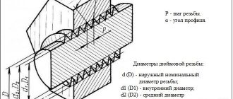
The main parameters of inch threads are diameter and pitch.
There are internal and external diameters. The internal diameter is defined as the distance between the lowest points of the recesses between the threaded ridges, which are on opposite sides of the part. The outer diameter of an inch thread is defined as the distance between the top points of the ridges, which are on opposite sides of the part. The difference between the outer and inner diameter determines the height of the thread profile.
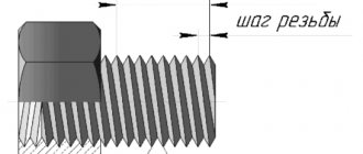
The pitch of an inch thread is the distance between two adjacent valleys or crests. For a thread to work, the pitch must be constant along the entire length of the cut thread.
Standard sizes are given in the table of parameters of inch threads with diameters and pitch:
Tool design
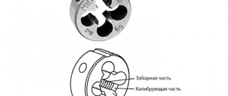
The UNF/UNC tap is a screw with flutes and corresponding sharpening of the front, back and other corners. The main elements of the tool are the cutting (taking) and calibrating parts, grooves for removing chips. The cutting part is made of high-speed steel or hard alloy. A suitable shank is available for manual use or installation in a chuck.
The advantage of the tool is the simplicity and manufacturability of the design, as well as high cutting accuracy and the ability to work due to self-feeding. The difficulty is the need to apply large cutting forces and friction forces, and difficulties in removing chips.
Depending on the design, UNF/UNC taps are divided into:
- manual or metalworking;
- machine-manual;
- machine;
- nuts and others.
Designation principles
To determine the main qualities, you need to understand its designation. The thread designation in the drawings is slightly different from those used by the manufacturer in the production of products. Thread tables allow you to determine the main characteristics only by designation.
The features of the marking include the following points:
- Symbol for the thread in question G.
- The diameter size is indicated after the letter. An example of notation is 1 ½.
- The symbol L indicates that the turns are left-handed.
- The next symbol H indicates the accuracy class.
- The make-up length is represented by numbers at the end of the marking.
The designation of a tapered thread in the drawing provides an indication of the accuracy class. A symbol indicating the accuracy class may be indicated in the technical documentation. The creation of turns is carried out in compliance with one of three classes. In addition, the letters “A” and “B” may be indicated next to the number: the first indicates an external indicator, the second internal. The first class corresponds to the coarsest threads, the third is the highest quality.