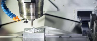
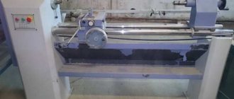
A turret lathe is often used to produce metal parts of various configurations. A special feature of turret machines is the presence of a multi-position rotating head, which is capable of carrying various tools for a number of technological operations (turning, drilling, countersinking and many others). Such devices, depending on the model and purpose, are manufactured with a standard design or supplemented with a CNC system.
Modern CNC turret lathe
Some features of the machines
The units described above are characterized by a fairly high level of performance. If we compare them with the most primitive turning installations, this is explained by a number of factors.
- The use of fast devices for feeding and hardening of workpieces.
- Combinatorial operation of the turret and transverse support.
- Quickly change the device used in the work.
- The use of new holders, as well as various tools that differ in their combined appearance.
To ensure high performance and proper functioning, you need to configure it correctly. Proper setting refers to the selection of tools that are used in the work and their installation in holders, as well as the manufacture and installation of a longitudinal or transverse stop. The stop will be adjusted in the axial or radial direction.
On many turret machines, the frequency, as well as the feed and rotation, will be selected using a command device. Chuck units that were produced in Russia or even in the Soviet Union can work with workpieces with a cross-sectional size from 15 to 60 cm. Rod equipment is characterized by the following parameters: the distance through which the head can move is maximally large, the cross-section of the products is small.
Simple turret machines are used in many domestic enterprises. In recent years, you can notice a tendency to exchange them for the most advanced equipment, which has numerical control. CNC machines have many advantages, they are characterized by a high level of automation and operation, as well as good processing accuracy.
Parameters for selecting turret lathes
The following parameters are distinguished:
- The distance between centers (RMC) determines the maximum length of the workpiece being processed (for example, for TS16K20F3 and TS1640F3 machines it is 1500 mm).
- The height of the spindle axis above the machine bed determines the maximum diameter of the workpiece. At the spindle head, certain models of lathes have a recess that allows processing larger disk-type workpieces. The higher the height of the axis, the greater the number of toolholder positions that can be applied (or the cross-section of the cutter increases)
- The spindle hole diameter characterizes the maximum diametrical size of the bar stock passing through the spindle head. This parameter is important when processing long workpieces, as well as when processing a series of short workpieces.
- The torque on the spindle (measured in N*m) characterizes the power parameters of the processing machine and the maximum drilling diameter of the workpiece, cutting depth and tool feed. Modern powerful processing lathes perform cutting operations on large heat-treated workpieces.
- Stepless speed control over the entire operating range of spindle rotation speeds or within the range (for example TS16A20F3) allows for more precise adjustment of cutting modes and higher spindle rotation speeds due to the absence of gear rotation speed restrictions.
- Maximum spindle speed: a value that determines the range of materials processed and the cleanliness of the resulting surface. Parts from viscous alloys are produced at high speeds.
- Machines with an inclined bed have a more rigid structure, which increases the rigidity of the entire machine-tool-workpiece system (TS1720F3, TS1720F4). They also provide convenience of chip removal (presence of a conveyor). Telescopic protection of the cutting zone increases the service life of the guides.
In any case, our company’s consultants will help you choose the right machine to suit your requirements. You can ask all questions by calling 8 (4822) 620-620.
Notes[ | ]
- What is a Lathe Machine? History, Parts, and Operation (English). Brighthub Engineering
. Retrieved March 26, 2022. - Clifford, Brian
A brief history of woodturning.
The Woodturner's Workshop
. Woodturners' Guild of Ontario. — “the first evidence of the lathe itself comes from the 3rd century BC but it is known that it was in use long before that. A flat wooden dish which stood on wooden legs was found in a pit grave at Mycenae dated at 1100 to 1400 BC… suggests that it could have been turned on a mandrel held between centers in a lathe. Against this view must be set the fact that there is no sign of turned grooves on the piece.” Retrieved July 24, 2022. - Clifford, Brian
A brief history of woodturning.
The Woodturner's Workshop
. Woodturners' Guild of Ontario. — “The earliest piece from that was found at a site known as the “Tomb of the Warrior” at Corneto. This is a fragment of a wooden bowl, dated at around 700 BC, which shows “clear evidence of rounding and polishing on its outer surface and of hollow turning...” (Woodbury) Other Etruscan turned vessels were found on this site. … Excavations of a mound grave in Asia Minor (now Turkey) revealed two flat wooden dishes with decorative turned rims. These have been dated as from the 7th century BC." Retrieved July 24, 2022. - Emperor's Ghost Army
(documentary). PBS. Time from the beginning of the source: 26:00. - Clifford, Brian
A brief history of woodturning.
The Woodturner's Workshop
. Woodturners' Guild of Ontario. — “The earliest information on the late dates from the 3rd century BC. This is a bas-relief carving on the wall of the grave of an Egyptian called Petrosiris.” Retrieved July 24, 2022. - Murthy, S. Trymbaka.
Textbook of Elements of Mechanical Engineering (English). — ISBN 978-9380578576. - Nartov Andrey Konstantinovich 1693 - 1756: brief biography, years of life, activities (Russian). histrf.ru. Retrieved January 26, 2022.
- Inimitable accuracy (Russian) // rusplt.ru.
- Andrey Konstantinovich Nartov - Inventions and inventors of Russia (Russian). www.inventor.perm.ru. Retrieved January 26, 2019.
- Tomiyama, Testuo
Development of Production Technology and Machine Tools (presentation notes).
Pages 18—21 (English) (PDF). OpenCourseWare: TUDelft
.
TUDelft (16 February 2016). — “1770 Jan Verbruggen Escaped to England with his Son Pieter Verbruggen (1734-1786) and Became Master Founder at Woolwich Arsenal.” Retrieved July 24, 2022. Archived July 25, 2022. 02. Ontwikkeling Fabricagetechnologie
. Delft, Netherlands: TUDelft.
Technical features of installations
Lathe units of this group also have some additional equipment - faceplates, three or four-jaw chucks. The latter operate thanks to a built-in drive, which can be manual or hydraulic. This allows processing of large workpieces. Most often, such parts can be obtained using casting, forging or stamping.
Some technical features have turret-type units, which are designed to work with rod elements. They are equipped with a spindle with a small hole. Also, these units have a special mechanism that ensures feeding and subsequent fixation of the workpiece in the desired position. If such machines are equipped with a suitable chuck, they are suitable for processing other parts that are produced by casting, stamping or forging.
The location of the axis about which the working head of the device rotates affects the number of supports. If it is horizontal, then an element is installed that is capable of only circular and longitudinal movements.
When the axis is placed vertically or at an angle, then two supports can be mounted on it - revolving and transverse. Two tool holders can be installed on the last element of the machine. They ensure the simultaneous presence of up to six working tools, which is very convenient during operation of the equipment.
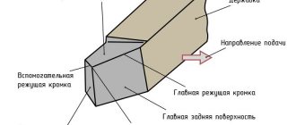
Tool holder
Safety precautions
Before working with equipment, you must undergo a medical examination. Operational and safety training is also required. It includes the following rules:
- Do only the work that is assigned to you, and only in a safe manner.
- Work only on equipment in which you have special skills.
- Work only in a special uniform, which is issued before starting work.
- The employee must be provided with ample space to work.
- Before work, it is necessary to check the serviceability of the device.
- Under no circumstances should you attempt to repair the device yourself. Do not touch the internal mechanism of the machine
- There should be no unnecessary items in the workplace.
- The workpiece must be firmly fixed.
- Do not touch the material being processed.
- Do not touch workpieces during operation.
Main design features
A universal screw-cutting lathe consists of main structural units, which are standard elements. These include:
- caliper;
- bed;
- thrust and spindle headstock;
- electrical equipment;
- drive shaft;
- guitar gears;
- a box that provides selection and change of feeds;
- lead screw - it is this detail that distinguishes a screw-cutting lathe from a standard lathe.
Depending on some features, the accuracy of the machine may vary. Therefore, universal equipment can be of both accuracy class N and increased – P.
Front and rear stock
The headstock or spindle has the main role of fixing the workpiece in processing and transmitting rotation to the workpiece from the electric motor.
The spindle is located inside the body of the headstock. A speed control handle is mounted on the outside of the machine body. The tailstock or thrust is necessary to fix the workpiece.
Caliper
The support is designed to move the tool holder with the cutter in the longitudinal, transverse direction relative to the axis of the machine. The lower part of the support is called the slide or carriage.
After a certain time of operation of the machine, the support will need to be adjusted, since otherwise the processing speed will decrease. Adjustment for gaps consists of tightening the wedge strip.
Compared to other parts, the caliper is large. The choice of tool holder is determined by the class of the machine. For large equipment, be sure to secure the cutters with an additional four screws.
Gearbox
This is the main part of the spindle drive. It transmits engine energy to the rest of the machine. Another function is to change the spindle speed and the operating speed of the entire machine.
The box is built into the spindle head housing or in a separate housing block. The speed can be changed in a stepless or stepwise manner. The standard gearbox includes the following components:
- gear system;
- V-belt transmission;
- reversible electric motor;
- electromagnetic clutch with braking system;
- handle for changing gears.
The gearbox operates using gears.
Spindle
This is the main part of the machine, which is made in the form of a shaft with a conical hole for securing workpieces. To ensure that the part has high strength and durability, it is made of high-strength steel.
In the classic version, the spindle is made on high-precision rolling bearings. A special ring is installed on the support of the part, which ensures the accuracy of the machine.
There is a conical hole at the end of the structure. The spindle needs a cavity to install a rod that helps, if necessary, knock the center out of the seat.
The strength and durability of the spindle directly depends on the bearings available there.
bed
This is the main part of the machine, which is made using cast iron. All the most important parts and elements of this design are attached to it.
The frame itself consists of two steel beams. The beams, in turn, are connected to each other by stiffening ribs. Each beam has a connection to two guides.
The guides on both sides belong to the prismatic group. The flat-shaped guide is located inside on the left side.
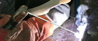
Threading
There are several ways to cut threads using a screw-cutting lathe. For this, a die, tap, cutter and other types of tools are used.
With their help it is possible to cut internal and external threads
When using a cutter, it is important to fully comply with the technology. It includes:
- correct sharpening of the cutter;
- accurate adjustment of machine operating modes;
- using a template, correct installation of the cutter in the center of the part;
- measuring the resulting dimensions using gauges or templates.
In such work, defects in the form of sharp points, torn threads, scuffing and crushing are unacceptable.
Electrical control unit
The standard control unit for a screw-cutting lathe includes several handles and buttons:
- handle for setting the number of revolutions;
- control system for setting cutting surface parameters;
- handles for caliper control.
A CNC machine has a more complex structure, but can work without operator participation at intermediate stages.
Apron
In the apron of a screw-cutting lathe there are mechanisms that convert the rotational movement of the lead screw and the lead shaft into the translational movement of the caliper.
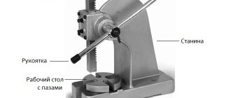
Design and operation of the automatic turret UG 9326
The design of the head is shown in Fig. 2.
The movement from the electric motor (17) built into the sleeve (21) of the housing (23) through a drive coupling made at the end of the rotor shaft (16) and the planetary gear carrier (24) is communicated to the satellite block (12). One of them is mated with a fixed internal gear (26), and the other with a movable gear (9), the hub of which has a trapezoidal thread and a gear coupling at the end. This coupling and screw (3) are used to connect the part (9) to the indexing control cam (4). The radial support of the part (9) is made of bronze half-rings (29), the end ones are the bearings (10) and (11).
Mating with the thread on the part (9) is a flange-nut (8) attached to the spindle (5) of the head, which can perform rotational and translational motion. A tool disk (1) and a locking coupling half (31) with a circular tooth are attached to the spindle. The second coupling half (30) is fixed to the head body.
At the end of the sleeve (21) there is a sensor (13) for the angular position of the tool disk, made on sealed magnetically controlled contacts (reed switches) and connected to the spindle flange via a roller (22) and a coupling (20). The sensor is protected by a casing.
In the niche of the housing there is a set of terminal clamps for the electrical communications of the head, the PC circuit of the engine and a microswitch (14) for controlling the clutch of the coupling halves (30) and (31).
The coolant supply to the tool disk is turned on by pressing the disk on the valve pusher (6), built into the bar (7), attached to the head body.
Head operation
The head operates in a cycle in which the fixed position shown in Fig. 2 is taken as the initial position: removing the force and disengaging the flat-tooth couplings, rotating the tool disk to a given position, preliminary fixing, engaging the couplings and compressing them with the required force.
When the engine starts, the part (9) and the cam (4) begin to rotate counterclockwise. Since the coupling halves (3O) and (31) are engaged and the spindle cannot rotate, due to the interaction of the threads on the part (8) and (9), the coupling half disengages. The end of disengagement marks the contact of the cam shoulder with the finger (35). As the rotation continues, the lock (34), under the influence of the bevels on the part (32), enters the groove on the cam, ensuring the coupling of the drive and the spindle. When the tool disk reaches the required angular position, at the command of the sensor (19), the motor is reversed to, accordingly, the direction of rotation of the head parts is changed. In this case, the clamps (33) and (34) fall into the holes of the flange (32), the cam is released and the drive and spindle are disengaged. With further rotation of the drive, the locking coupling halves are engaged and the necessary tension is created on them, the magnitude of which depends on the installation of the current relay of the motor circuit in the electrical circuit of the machine. The current relay controls the shutdown of the electric motor.
Basic adjustments
The rotation of the spindle should begin after it leaves the clutch of the coupling halves by 0.5 ± 0.2 mm. This value is adjusted by moving the cam along the end teeth of the part (9). A shift of one tooth results in a spindle movement of 0.45 mm.
To properly fix the spindle, it must be overtraveled relative to the given position by 5°…3°. This value is set by turning the sensor (19).
The microswitch (14) must operate 0.5...1.5 mm before the end of the spindle stroke; this is achieved by moving the microswitch bar (13).
Repair cost
| Type of work | Price |
| Spindle Prevention | 9,000 rub. |
| Troubleshooting clamping devices | 19,000 rub. |
| Burnout (damage) of the stator winding | 30,000 rub. |
| Replacing bearings with rotor balancing | 50,000 rub. |
| Replacing spindle sensors | 10,000 rub. |
| Maintenance | 10,000 rub. |
| Non-standard work | 10,000 rub. |
| Major renovation | 50,000 rub. |
| Modernization of machine tools | 30,000 rub. |
Our main specialization is machine repair
If your machine does not work, our specialist will arrive as soon as possible and fix it. Call and consult by phone: 8
- Thanks to the use of modern devices, we can more accurately identify faults. And we save your money on repairs
- If your machine does not break down as usual. We will send it to our technicians and they will solve any problem
Read useful information:
Repair of the electrical part of the machine
The slightest malfunction of the electrical part of the machine can disrupt the plant’s work schedule
It is important to be able to identify the source of the problem and eliminate it
Further
Machine head repair
The headstock is an important element of the machine. If this part fails, it is very difficult to cope with the repair yourself and you have to contact specialized workshops
How to prevent breakdowns, what is important to know when doing your own repairs and how much the services of qualified craftsmen cost - all this can be found in the article
Further
Self-repair of the machine shaft and care for it
In the modern world, the use of complex equipment is associated with wear and tear. In particular, the shafts of various machines are subject to enormous loads due to the large volume of work, and sometimes due to the conditions in which they are operated. The article discusses the main causes of breakdowns, as well as methods of prevention and maintenance of equipment. Questions about repairs for various damage to machine shafts are also covered.
Further
Machine repair cost
Any equipment with insufficient care and untimely diagnosis fails. In this article, the reader can find information about the types of machines, common breakdowns, as well as the actions of a specialist during repairs.
Further
Machine support repair
In the modern world, various machines are widely used, because... they allow you to perform many operations. This unit consists of many parts, where the main role is played by the machine support. And it often happens that the work of the tool freezes due to the breakdown of the caliper or other parts.
Further
When concluding a long-term service agreement, you receive a discount of up to 20%. Don't forget, we have a guarantee on all types of work.
- engineer - mechanic
- CNC programmer
- Service engineer
- Electrician
- Electronics engineer
- Locksmith - repairman
Classification
Thanks to its universal design, the CNC turret lathe can be designed with almost any configuration. On this basis, a distinction is made between general-purpose equipment and specialized models.
The most important parameter to select is the location of the rotating turret. Its location will determine the possibility of performing one or another type of turn.
• With longitudinal feed. This design is typical only for processing parts along a horizontal axis. Used in semi-professional equipment. A small set of functionality. But
the machine has a relatively simple design, which affects the complexity of its maintenance and repair;
• Longitudinal and transverse feeds. Installed on models with vertical and inclined position of the lathe. The ability to move the cutting part along two axes increases the range of operations.
- There are only two types of workpieces that we can process on machines of this group - bar and cartridge. For example, cartridge shafts include shafts of fairly large diameters, and rod shafts include long rods, but with a small diameter.
- Lathes in this group can be horizontal, vertical or inclined. The model on which the workpiece can be placed in horizontal and vertical positions is extremely popular, while inclined machines are very rare. Inclined models make it possible to perform the desired tilt of a part for turning holes, or performing any other operations that can only be performed at an angle.
The passport of a turret lathe contains all the necessary information that may be needed when choosing a specific machine. There are models that can be equipped with faceplates with 3 or 4 cams, which are driven by hydraulic drives. This fact makes it possible to process parts that have large dimensions. For example, this could be a workpiece that was obtained by forging or casting.
Types of work performed
Analyzing the data given above, we know that the performance characteristics of the latest turret lathes allow them to perform a variety of operations. The part can be completely different workpieces, which are, as a rule, a body of rotation.
Let's look at the most popular types of operations that can be performed on turret lathes:
- Turning the outer diameter (roughing and finishing passes are carried out)
- Turning, end trimming, in addition, you can cut the workpiece using a cutting lathe.
- External and internal thread cutting using different cutters.
- Turning external grooves, which can take different shapes and the desired depth (performed using the desired cutter).
When studying the passport of a turret lathe when choosing, you need to pay attention to the fact that threads can only be cut using a tap or die. To achieve this point, it is necessary that the tool fastening device have special holders that can move along the axis.
Settings
The machine is set up by starting a series of identical parts. It provides:
- development: part manufacturing technology;
- setup cards;
- spindle speed;
https://youtube.com/watch?v=_yb2NaWntls
Purpose and design of CNC turret lathes
When manufacturing medium and large batches of parts on screw-cutting lathes, it is customary to carry out step-by-step metal processing, since each operation requires its own processing modes, type of cutting tool and other equipment settings (for example, checking the zones of mutual influence of cutters). In mass production, such machines often operate in pairs (or using a counter-spindle), forming a single production line, where a product processed on one side is transferred to another machine for further processing. This is due to technological complexity and the impossibility of processing the entire workpiece to the finished product on one machine without readjusting the machine (the number of operations exceeds the number of positions in the turret).
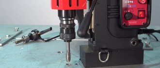
CNC lathe-turret group (two-support, with an inclined bed):
| 1 - engine; 2 — spindle head; 3 — upper longitudinal-transverse caliper, 4 — turret head of the upper caliper; 5 - tailstock; 6 — turret head of the lower caliper; 7 — lower longitudinal-transverse support of the machine. |
Precise processing of products using CNC machines requires competent basing of the workpiece (selection of technological base) and refined settings of the cutting tool (for example, using the HPMA system from Renishaw). This is especially true for parts with complex configurations, with tight tolerances and high requirements for surface accuracy.
By programming the CNC of the machine module and calibrating the cutting tool, the processing accuracy is set. If the head axis can be positioned at different angles to the workpiece, parts with more complex surfaces are obtained.
Links[edit]
- Hartness 1910.
- Editors (1924). American machinist. McGraw-Hill. paragraph 273.
- ^ ab Crosher, William P. (2014). Chronology of broadcasts. Bloomington, IN: Xlibris. paragraph 144. ISBN 978-1499071146.
- ^ a b Rolt 1965, p. 165. harvnb error: no target: CITEREFRolt1965 (help)
- ^ ab Editors (1901). "Part 5: Turning works". Reading working drawings. Arithmetic. Measuring instruments. Turning works
. Coal Mining Engineering Company. pp. 3–11. - ^ a b Bawa, H. S. (2004). Production processes
.
1
. New Delhi: Tata McGraw-Hill. paragraph 57. ISBN 0-07-053525-6. OCLC 57660758. - ^ ab Smid, Peter (2003). The CNC Programming Handbook: A Comprehensive Guide to Practical CNC Programming (2nd ed.). New York: Industrial Press. pp. 11 -14. ISBN 0-8311-3158-6. OCLC 52364066.
- Differences between spire and turret
- HW Ward & Co., Ltd 1938.
- ↑
Rowe, 1937, pp. 34–36. harvnb error: no target: CITEREFRoe1937 (help) - Editors (1921). ASME Mechanical Catalog and Reference. American Society of Mechanical Engineers. item 456.
- Hounshell 1984.
- Parker, Dana T. Victory in Construction: Aircraft Manufacturing in the Los Angeles Area During World War II,
pp. 81, 123, Cypress, CA, 2013. ISBN 978-0-9897906-0-4.
Design Features
The technology for creating turret lathes is quite complicated. The device has a very complex design, which consists of several elements:
- Gearbox.
- Caliper.
- Spindle assembly.
Gearbox
The device’s speed box is responsible for the number of revolutions performed. The speed of the machine changes with the number of revolutions.
The mechanism contains 3-4 electromagnetic clutches, which determine the number of speeds of the device. The coupling consists of metal discs.
As a rule, each machine contains 4 clutches: 2 electromagnetic and 2 overrunning. Between them there is 1 double-crown gear block. It ensures the operation of the gearbox parts, allowing the gears to change.
Caliper
The lathe support is responsible for moving the cutter along the spindle axis.
The part is a cross-shaped structure consisting of 3 elements: a carriage, a cross slide and a cutting slide.
Spindle assembly
The components of a metal-cutting turret machine transmit energy from the engine to the working tools.
The spindle contains 8 nodes:
- The bed connects the units of the device.
- The headstock fixes and rotates the material being processed.
- The tailstock installs the cutting tool.
- The support moves the cutter along the axis.
- Feed box transmission of movement.
- The drive shaft tells the caliper that there is material to process.
- Lead screw thread cutting.
- The apron stops the drive shaft and activates the caliper.
Gearbox
Its kinematics takes into account the transmission of rotation from the electric motor shaft through gears:
- spindle;
- feed box;
- devices of the caliper apron for its movement with a given feed;
- thread cutting device.
The support moves along the guides of the additional frame using a toothed bar.
The support contains:
- turret;
- command apparatus;
- stop drum;
- apron.
The head is fixed to the shaft located on the support. The shaft rotates on ball bearings. The tool is attached to the head holes using holders. Holders provide rigidity of fastening, accuracy of installation and adjustment of the tool.
This shaft is used to fasten the command device and the stop drum. The head rotates after any working stroke, delivering such a tool to the processing zone. The command device ensures automatic activation of the required spindle speed and feed values corresponding to the given type of tool.
Behind the command device there is a stop drum, which ensures automatic stop of the caliper when the required amount of tool movement is reached. The feed is switched off by cams installed in the grooves of the drum when they reach the folding stop.
Turret lathe 1341
With the help of the influence of the cams, the activation of the specified electromagnetic clutches in the gearboxes and feeds is ensured. This makes it possible to obtain the values of spindle rotation speed and feed specified for this procedure.
Turret lathes
Turret lathes differ from screw-cutting lathes in that they do not have a tailstock and a lead screw, and a rotary multi-position turret head is installed on the longitudinal support, in the sockets of which various cutting tools are installed, and when using special combined holders in one Several cutting tools are installed in the turret socket. Each cutting tool, when turning the head, sequentially processes the part. Turret heads are prismatic and cylindrical.
Turret lathes are recommended for use in mass production when the size of parts in a batch is at least 10 - 20 pieces.
| General view of a turret lathe. |
Turret lathes differ from conventional lathes in that work on them can be carried out by a set of cutting tools of several types installed in a certain sequence in the turret and on the transverse support.
Turret lathes differ from conventional lathes in that work on them can be carried out by a set of cutting tools installed in a certain sequence in the turret and on the transverse support. Therefore, turret lathes are more productive than conventional lathes and, as a rule, are used in mass production.
In some cases, turret lathes allow the use of special devices to automate the processing cycle, including loading workpieces and removing them from the machine after processing.
| The layout of the working bodies, installed at an angle when reproducing the screw guide -. line. |
Turret lathes (Fig. 1.48) have a layout characteristic of conventional lathes.
| General view of the turret lathe model Shch365. |
Turret lathes are designed for processing parts of complex shapes in mass production, including... The processing process on these machines consists of several sequential operations, during which various tools are used: cutters, drills, taps, etc., mounted in a so-called turret, which is mounted on a support. In electrical engineering, turret lathes are used to process bearing shields, bushings and pressure cones of electrical machine commutators. The use of these machines increases labor productivity by 2–3 times compared to processing on screw-cutting lathes.
Turret lathes are designed for processing workpieces of complex shape (stepped, etc.), which in some cases have a central hole. To produce such parts, it is necessary to consistently use a variety of cutting tools.
Turret lathes are designed for processing workpieces of complex shapes (stepped, etc.) and especially workpieces that have a stepped central hole. To produce such parts, it is necessary to consistently use a variety of cutting tools.
Turret lathes are used in serial and large-scale production when using a group method of processing parts, when parts of similar shape can be processed using the same technological process on the same machine and fixture with minor readjustments.
| Schemes for processing shaped surfaces. |
Turret lathes are designed for processing parts from rods or piece workpieces. They can perform almost all types of turning work. Parts to be processed on turret lathes have several machined surfaces, which determines the need for multi-tool setup. The turret head allows such adjustment, as it has several slots for attaching tool holders. The holder, in turn, can also accommodate several tools. The combination of a transverse slide with a turret makes it possible to process several surfaces of a part at the same time. Multi-tool setup of machines requires a significant amount of time, so turret lathes are used in mass production.
Frontal machines
The main purpose of frontal lathes (Fig. 3) is to process parts of large diameters and small heights. These machines are used to produce massive flywheels for the engines of mining dump trucks and ships, wagon wheels, slewing rings for lifting cranes, etc. The main distinctive feature due to which frontal machines are separated into a separate group is the presence of a large-diameter faceplate.
Figure 3. Face lathe.
The frontal lathe includes the following main components.
- Massive bed. It is the base of the machine.
- Caliper base. Serves as a caliper guide. Contains feed control handles.
- Caliper. Moves the faceplate to the processing area. Has automatic feed settings.
- Headstock. Includes an electric motor, gearbox and machine control mechanisms.
- Faceplate. Designed to secure the workpiece.
- Tailstock. The cutting tool is fixed in it.
Unlike rotary lathes, which are also designed to work with parts of large diameter and low height, frontal lathes have restrictions on the weight of the workpiece. If the workpiece exceeds the permissible weight, it is processed on a rotary machine.
Purpose
The mechanisms under consideration are designed for working with short cast iron and steel parts of large or uneven diameter. They are also suitable for turning heavy cylindrical workpieces.
A metal lathe is usually used for processing edges or end parts, cutting threads, grinding ends, boring holes, trimming ends, turning channels, etc. Thus, these devices are used for turning shafts, pipes, disks, producing rings, flanges, disks, gears, pulleys.
They are usually found in single releases and repairs. However, due to the labor-intensive installation of the workpiece, as well as low productivity and accuracy, devices of this type were replaced by carousel models of a more advanced design.