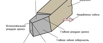
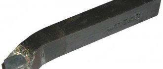
The cutter is the main tool when performing turning work. By cutting off excess metal, the part takes on the desired shape.
They move in the longitudinal and transverse directions, are made of different materials, differ in the type of installation and purpose.
What are the current standards and the explanation of their markings?
The main standard by which turning tools are manufactured is GOST:
- Cutting and groove - GOST 18874-73.
- Boring - GOST 18872-73.
- Walkthroughs - GOST 18871-73.
- Shaped - GOST 18875-73.
- Threaded - GOST 188885-73.
Marking according to the material of the working part:
- Tungsten - VK8, VK2.
- Titanium tungsten - T5K10, T15K6, T30K4.
- Titanium-tantalum-tungsten - TT7K12, TT8K6.
- High carbon steel - U10A, U12A.
- High-speed steel of normal efficiency - P9, P12, P18.
- High-performance high-speed steel - R18F2, R18F4, R6M3.
This is interesting: How to restore chrome: cleaning and restoration of chrome coating
Types of metal cutters
Cutters for a lathe are also divided according to the category of work performed. Each type is as close as possible to certain actions and is rarely suitable for others. This option should be chosen especially carefully.
| Type of cutter | GOST | Modifications | Action to be performed |
| Scoring | 18880-73 18871-73 | bent persistent bent | For processing end cuts on machines with transverse feed. The shape of the active plate is triangular. Processing is carried out perpendicular to the axis of rotation of the blank blank. |
| Boring | 18882-73 | for closed holes for through holes | For boring holes. The diameter is limited by the length of the holder. |
| Cut-off | 18884-73 | For cutting blanks and metal sheets at right angles. Suitable for cutting grooves. | |
| Passage | 18878-73 18877-73 18879-73 | straight bent persistent bent | For processing the external surfaces of cylindrical blanks, including end ones. Suitable for chamfering. Work along the axis of rotation of the workpiece. |
| Threaded | 18885-73 | for external thread for internal thread (only for machines with guitar) | For creating various carvings. Mostly metric, but by changing the sharpening you can achieve a different look. Internal thread - only on large diameters. |
| Chamfered | 18875-73 | For creating complex shaped surfaces with different depth levels. | |
| Prefabricated | Universal type with fastenings for plates for various purposes. | ||
Classification of turning tools
The production and division of these parts into individual types takes place according to a special GOST. This document states that the following tool categories exist:
One-piece devices that are made entirely from alloy steel alloy. There are also parts made of tool steel, but they are quite rare.- Cutters with soldered carbide plate. This tool is considered the most popular.
- Cutters equipped with removable carbide plates secured to the working element using clamps and screws.
Metal cutters also differ in the direction of the feeding movement during operation. So, the following types are distinguished:
- Left-handed tools - when working, such cutters are fed from left to right. If you place your left palm on this device, its cutting plane will be located next to the thumb.
- Right-handed incisors are characterized by a feed from right to left.
Straight and bent through tool
Straight cutters are often used to machine the outer surfaces of cylindrical workpieces.
There are two most common sizes of tool holders for this tool:
- Square - 25x25 mm (designed for special types of work).
- Rectangle - 25x16 mm.
Pass-through bent products are used for processing end surfaces. In addition, this tool allows you to perform high-quality chamfering and many other jobs. The holders of this device can have different sizes. The requirements for this tool are regulated in GOST 18877–73.
Thrust, scoring and parting
Thrust devices can be produced with a bent or absolutely straight working element. This tool can be used to process cylindrical workpieces made of metal alloys. In addition, it is the most popular type among many professionals.
The appearance of scoring cutters is similar to that of a cutting cutter, but the first tool has a triangular cutting blade made of a hard metal alloy.
The cutting type of tool is considered the most common. These cutters are used to cut material at an angle of 90 degrees. They are also used to make all kinds of grooves on the surface of metal parts. It is not difficult to find out that you have a cutting-type tool in your hands. A characteristic feature of this device is a thin leg on which a carbide plate is soldered.
There are other types:
- for cutting internal and external threads;
- for processing blind and through holes.
All types of turning tools have their own characteristics and are designed for different types of processing.
Cutting tools for CNC machines: types, characteristics, requirements
In order to achieve excellent performance and excellent quality of part processing, each cutting tool for CNC machines must meet certain requirements. Careful selection and preparation of the necessary tools, ensuring technical reliability, automation of the working process of a CNC machine, includes matching the high level of strength of such devices with their versatility.
For the production of cutting tools they use:
- hard alloys;
- metal ceramics;
- high-speed steel;
- synthetic materials.
Moreover, hard alloys, in turn, are also divided into several groups that differ in their operational, physical, and chemical properties:
- titanium-tantalum-tungsten;
- without tungsten;
- tungsten;
- tantalum-tungsten.
About the basic requirements for cutting tools
CNC production machines generally must use cutting fixtures that satisfy a number of conditions, such as:
- stability of cutting properties;
- correct formation and removal of chips;
- versatility of use for processing different types of parts on different types of machines;
- their rapid replacement for readjustment, processing of other parts, or changing a dull tool;
- ensuring the necessary precision in processing parts.
Attention. In some cases, the above requirements for cutting tools may not allow the use on CNC devices of those that are successfully used on conventional machines. For such modern machines, special groups of cutting, standardized devices are now allocated.
About tools used on lathes
For processing parts on lathes, the following are usually used:
- incisors;
- different types of drills;
- sweeps;
- various cutters;
- taps.
About the features of using cutters
Most often, in a conventional lathe, special cutters are used as a special cutting tool, having standard designs of an established type. Usually they are prefabricated, equipped with multifaceted special plates made of hard metals and various superhard materials (SMP).
There are certain requirements for such cutters:
- maximum use of plates that are mechanically fixed to their body to ensure constant, geometric, structural properties;
- the use of plates of the most optimal shapes, which will ensure universal operation of the tools;
- the ability to provide for all the actions of these devices in a straight or inverted position;
- allow the left-hand cutter to operate;
- guaranteeing high reliability of cutting inserts;
- correct formation of chips for their removal along special grooves made on the front sides of the plates used.
About the types of incisors
Typically, a set of cutting fixtures used by such a CNC machine contains typical cutters of this type:
- pass-through, bent on the right side by 45° to ensure chamfering, external turning of the end sides;
- contour cutters with plates in the form of a parallelogram, allowing you to turn cylindrical, contour parts, and turn conical parts up to 30°;
- contoured, with special parallelogram-shaped plates for the ability to process hemispherical surfaces and cones up to 57°;
- threaded, having rhombic plates that are fixed on top, making it possible to cut threads with a pitch distance of 2 to 6 mm.
About replaceable polyhedral plates (SMP)
Prefabricated cutters with SMP plates have gained the greatest popularity; their widespread use on CNC machines is due to such factors as:
- economical consumption of cutting scarce cutters;
- reduction of time for setting up tools, in which the change of SMP can be done without removing the cutter body;
- good quality of chip crushing;
- there is no need to constantly sharpen the cutter itself.
Dependence of cutting tool productivity on plate fastening methods
In prefabricated devices, productivity, as well as reliability, endurance, and longevity of their operation, depend on the methods of fastening multifaceted plates. These fasteners must provide:
- reliability (without possible microscopic displacements during movement made by cutting tools);
- density of surface contact between the support plates and grooves;
- precise positioning and the possibility of mutual replacement of working edges;
- support for geometric stability;
- crushing and reliable removal of chips;
- the shortest time allowed for changing blades.
About tools used for milling machines
For milling, cutters are used as cutting devices, which come in various designs and have special teeth for processing the surface of parts.
All milling tools differ from each other in:
- the shape and appearance of the teeth;
- their direction and execution;
- their use and fastening.
In order to properly strengthen the cutter in the chuck of a milling machine, use its shank, which is attached to the teeth by welding or with various fasteners, for example:
- bolts;
- special wedges;
- screws.
Sometimes the cutter can be presented as a single unit with its cutting part. That’s what they usually call it – a solid cutter.
Important. Some modern CNC machines use only one-piece special end mills that have cylindrical and also conical shanks for more durable, quick fixation in the chuck of milling machines.
The following materials are most often used in the production of milling tools:
- metal ceramics;
- high-speed cutting steels;
- hard alloys with special diamond coatings to enhance hardness.
About the principles of milling
When milling, using the teeth of a cutter, chips are removed from the surfaces they grind, and they are removed from the cutting zone by special grooves along the cutter itself. Therefore, the location of the teeth relative to each other is of particular importance. Correct geometric relative position affects:
- cutting speed;
- quality of processed surfaces;
- wear resistance of the cutter;
- saving energy costs;
- price of finished products.
Attention. Each type of intended workpiece, be it wood, stone, metal, plexiglass, for example, requires a certain type of milling device.
About the types of cutters
These instruments come in a variety of types, which are usually classified into certain groups, united by a common feature. Such signs include, for example:
- design features;
- geometric shapes;
- types of processed parts.
Design features include cutters:
- solid, made from one type of material as an indivisible whole with its own cutting side;
- compound cutters, characterized by a toothed part made of durable steel, soldered or welded to the shank;
- prefabricated, in which the toothed part is attached to the shank in a simple mechanical way (using bolts or screws).
According to their geometric type, such cutting devices include cutters:
- end;
- cylindrical type;
- end;
- conical type.
The milling operation is associated with cutting actions performed on the surfaces of various parts, for example:
- grinding surfaces;
- cutting grooves;
- cutting various types of threads;
- simple cutting of metal.
There are also standardized cutting tools, depending on the type of workpiece being processed, for example, milling cutters for processing:
- copper, aluminum and other ductile metals;
- stone;
- wood;
- plexiglass;
- become.
In such cases, the material of the cutting parts themselves on the cutters depends on the rigidity of the workpiece being processed and, accordingly, on the design of special grooves for removing chips, which can be:
- plastic;
- small;
- large;
- fragile.
About the features of selecting cutting tools
Nowadays it is difficult to imagine a modern CNC milling machine without appropriately suitable special milling tools, without which significant productivity cannot be achieved. Precision processing of parts and ease of use are the main criteria for the strict requirements placed on them.
On such machines, the cutting tools are often cylindrical end mills made of carbide or diamond materials. Their advantages include:
- possessing high wear resistance;
- ability to withstand vibration during rotational motion;
- increased rigidity;
- high cutting speed;
- very high processing accuracy.
All modern machines with numerical control can perform the most complex technological operations, automatically performing the necessary processing of parts. Moreover, the parts can be made of cast iron, light metal alloys, and steel. All actions of such devices are programmed before the start of the work process. That’s why it’s so important to choose the right cutting tools that meet all the necessary requirements and parameters.
vseochpu.ru
Making your own cutters: a step-by-step guide
The main thing is to use only tool steel that has sufficiently high performance characteristics.
Experts recommend choosing an alloy or high-speed carbon version.
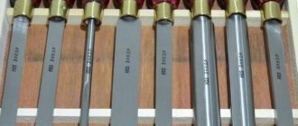
Selecting the required configuration of files or rasps
The selection of these parts will be easier if the owner knows in advance exactly what tasks he faces. After this, choosing the length, shape and size will not be difficult. Here are some tips.
- If you need to file up to 5-10 mm in thickness, it is better to stop at cut number 0 or 1.
- The processing accuracy should be within 0.01-0.02 mm.
- It is much easier to choose devices based on length.
The main guideline is the dimensions of the surface that needs to be sawed. The larger this parameter, the larger the device itself should be.
You can use a specific formula to make the calculation more accurate. We add 15 cm to the length of the surface of the product. We get the value, which will be the length of the working surface of the file or rasp. The main thing is that when working, the tool is passed over the entire workpiece.
Fastening cutting parts
Homemade tools do the same as professional ones. The optimal solution is self-tapping screws. The higher quality the product, the better.
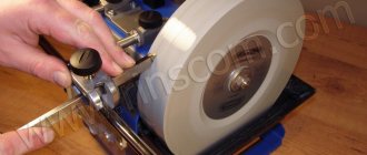
Tool sharpening
Only regular sharpening of the cutters will allow you to obtain the most accurate results. The need for the procedure arises not only for instruments that have disposable carbide inserts. The work is performed by specialized machines when it comes to large-scale manufacturing enterprises.
There are practically no restrictions on the method for home use. Suitable for use with conventional sharpening wheels and chemically active reagents. Machines for universal, specialized purposes are a cheap option that maintains efficiency.
When processing the back of a tool, there are three main stages.
- Maintaining the same angle as the holder itself at the back. The increase in the indicator compared to the rear cutting angle is 5 degrees.
- The second stage involves processing the surface of the cutting insert itself from the back. Here we need to keep the excess equal to 2 degrees.
- Finishing is the third stage. It is needed to form the required rear angle.
The front surface also goes through several processing stages.
Refinement and polishing
This is done with carbide on a special cast iron disk. The device rotates, maintaining a speed of up to 1-2 m/s. The direction of rotation of the disk itself is towards the working edge, away from the supporting part of the tool.
Consistently grind the blades and tool surfaces. The incisors are almost brought to a shine, and any irregularities are removed.
Why is fine-tuning needed? A tool becomes dull and wears out over time if it is used often enough. The reason is that the plate rubs against the workpieces and chips. If the plate is smoother, there will be less friction. In this situation, tool wear slows down.
The finishing process has other features:
- When finishing, abrasive pastes are used, the main component of which is boron carbide.
- Finishing involves wetting the tool with kerosene.
- Then the paste is applied to the surface in a zigzag manner.
- The instrument is brought to the disk.
- GOI paste can be used in conjunction with kerosene.
- Kerosene is not a mandatory step when using modern lubricants.
It is important to install the support table correctly. After its installation, in comparison with the middle part of the disk, the cutter blades with the part are on the same lines, or lower. The rotation of the disk is directed towards the threaded plate.
The paste particles begin to be crushed when the tool is pressed and finishing is started. The cutter has no chips or abrasions when passing through the edges. Irregularities on the incisal surface are eliminated thanks to the very grains of the paste.
Cutting tool
All tools used in metalworking can be divided into cutting tools (cutters, drills, taps, etc.), which directly carry out machining (cutting), and auxiliary tools, which serve to secure the cutting tool in the machine spindle (chucks, holders, mandrels) .
Machine tools can have different basic spindle tapers, and the cutting tool, in turn, is made with different types of shanks.
The basic cone of the machine is the spindle exit, made in accordance with one of the standard options. There are metric cones (7:24 or ISO 7388.1), Morse cones (domestic milling machines or drilling group equipment), HSK (modern machines designed for high-speed processing).
Thus, the auxiliary tool is a kind of adapter between the machine spindle and the cutting tool. The combination of cutting and auxiliary tools is called a tool block. Note that the tool block may contain several auxiliary tools and only one cutting tool (the main one). Large tool blocks reduce the rigidity of the technological system and reduce the accuracy of installation of the cutting tool, resulting in worse processing conditions and product quality.
Rice. 2.4. Milling cutters with mechanical fastening of cutting inserts
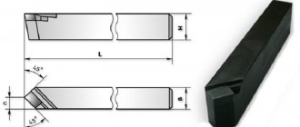
According to technological characteristics, cutters are distinguished for processing planes, grooves and splines, gears, threads, shaped surfaces, for cutting material, etc.
By design they are distinguished:
- according to the design of the cutter (solid, composite, with insert teeth);
- according to the design of the tooth (with sharpened teeth, with backed teeth);
- in the direction of the tooth (straight, inclined, screw teeth);
- according to the method of fastening (mounted, tail-mounted - with a cylindrical or conical shank).
According to the material from which they are made: high-speed steel, carbide, etc. In modern tool practice, the lion's share is made up of solid carbide or high-speed tools, as well as tools with mechanically fastened cutting parts (plates). Hard alloys allow working with cutting speeds that are 5–10 times higher than the processing speeds of high-speed tool steels, and have greater temperature resistance and wear resistance. When choosing a cutter, the technologist is primarily guided by the following parameters:
- diameter and length of the working part;
- profile shape of the working part;
- working part material;
- number of teeth (cutting edges);
- shape and size of the fastening part.
Rice. 2.5. Solid end mills
A conventional end mill has several cutting teeth (2, 3, 4, 6 or a rectangular profile of the cutting part. The cutter teeth are separated by helical grooves, which ensure removal of chips from the cutting zone. In the case when it is necessary to obtain a transition from one surface to another with a certain radius, cutters with a ball end or a small radius at the base of the profile are used. Ball end cutters and ball end cutters are often used for machining complex surfaces, such as dies and molds. Conical cutters are used for milling inclined surfaces and undercuts.
End mills are the most versatile - they allow you to machine planes, grooves and shoulders. There are other types of cutters: face, disk, slot. These cutters, as a rule, are used to perform milling operations with a “narrow” focus. For example, a face mill is the best tool for milling an open plane, while a disk mill is best for cutting a deep, narrow slot in one pass.
Rice. 2.6. Face mill and cutting insert
Milling cutters with mechanical fastening of hard alloy plates and other tool materials have become widespread. The bodies of such cutters have special seats in which the plates are installed. Fastening the plates to the steel body is usually carried out using ordinary screws. The plates have several edges, and if one of them wears out, it is possible to rotate the plate with a “fresh” edge. When all the edges are worn out, the plate can be thrown away and a new one installed. It turns out to be a very economical solution, since solid carbide cutters are quite expensive. Modern cutting inserts are designed to withstand a variety of conditions and vary in rake geometry.
The pitch of the cutter teeth can be coarse, normal or fine. Milling cutters with different tooth pitches are designed for different machining conditions in terms of stability, energy consumption and the presence of vibration. A reduced number of plates is a standard solution for productive processing with insufficient machine power or low rigidity of the AIDS system (machine - fixture - tool - part). Normal pitch cutters are universal for most operations. A small pitch or the maximum number of plates on a cutter body of a given diameter is recommended for processing with high rigidity of the AIDS system, as well as when milling materials that produce elemental chips, titanium and heat-resistant alloys.
The thickness of the cut layer during milling is affected by the leading angle, which is measured between the main cutting edge of the insert and the machined surface. Reducing the entering angle results in thinner chips for a given feed range. The reduction in chip thickness occurs due to the distribution of the same volume of metal removed over a larger length of the cutting edge. At a smaller approach angle, the cutting edge gradually enters and exits the work. This reduces the radial component of the cutting force and protects the cutting edge from possible breakage. On the other hand, an unfavorable factor is an increase in the axial component of the cutting force, which causes a deterioration in the surface roughness of thin-walled parts.
At an entering angle of 90°, the cutting force is directed radially in accordance with the feed direction. The main area of application for such cutters is the processing of rectangular shoulders.
Rice. 2.7. Leading angle 90°
When working with a milling cutter with a 45° entering angle, the axial and radial cutting forces are almost identical and the power consumption is low. These are cutters for universal use. They are especially recommended for processing materials that produce elemental chips and are prone to chipping under significant radial forces at the tool exit. When plunging the tool, there is less load on the cutting edge and less tendency to vibration when secured in fixtures with low clamping forces. The smaller thickness of the cut layer at a cutting angle of 45° allows you to increase the minute feed of the table, that is, increase processing productivity.
Mills with a leading angle of 10° are recommended for longitudinal milling with high feeds and plunge milling, when small chip thicknesses and high speed parameters are characteristic. The advantage of processing with such cutters is low radial cutting forces. And also the predominance of the axial component of the cutting force in both radial and axial feed directions, which reduces the tendency to vibration and provides great opportunities for increasing material removal rates.
Rice. 2.8. Leading angle 45°
For cutters with round inserts, the leading angle varies from 0 to 90° depending on the depth of cut. These cutters have a very strong cutting edge and can operate at high feed rates because they produce fairly thin chips over a long cutting edge length. Round insert cutters are recommended for machining difficult-to-cut materials such as titanium and heat-resistant alloys. The direction of cutting forces varies along the radius of the insert, so the direction of the total load depends on the depth of cut. The modern geometry of round inserts makes them more versatile, providing a stable cutting process, lower power consumption and, accordingly, lower requirements for equipment rigidity. Currently, these cutters are widely used for removing large volumes of metal.
Rice. 2.9. Round insert cutters
planetacam.ru
Tips for choosing quality cutters when purchasing
To choose the right cutters for a particular case, you need to rely on the following important parameters:
- Which metal is processed most often? What operations are performed on the equipment?
- It is important to prioritize in advance between wear resistance, processing efficiency and product quality.
If a turner is just starting to work, then he only needs to purchase three types of tools:
- Boring SDQCR.
- Neutral external type
- Pass-throughs for processing ends. SDACR.
Sets with lathe cutters are relevant if long-term operation is planned. The advantage is kits with replaceable plates. There is no need to purchase new holders; it is enough to change the consumable components.
As for manufacturers, here are a few names worthy of attention:
- Caliber.
- Sieve.
- Proma from the Czech Republic.
- Hoffman Garant from Germany.
The first two manufacturers are Russian. It would be important to purchase a special sharpening machine. Then, if the incisors wear out, returning them to working capacity on your own will not be a hassle. No need to waste time waiting for the masters.
Two wheels with abrasive properties and support for the cooling system are becoming important components for modern sharpening and grinding units. One disk is made of silicon carbide, the other is based on electrocorundum. The front part of the cutter is processed first, followed by the rear surfaces and the addition. The goal is to obtain a smooth edge that can cut through materials.
This is interesting: How to weld stainless steel with ferrous metal: technology features
How to install on the machine
To obtain the proper quality and precision of processing, correct installation of the cutter is necessary. Also, installation errors contribute to rapid wear of the cutting edge.
The tool is installed in the tool holder strictly in the center. To adjust it in height, the turner must have metal plates with a thickness of 1 to 4-5 mm in his arsenal. Setting below center causes the part to be pushed out, which is dangerous for both the tool and the worker. If the cutting edge is too high, it overheats and wears out quickly.
When installing a cutting tool, you need to follow simple rules:
- Wipe the supporting surface of the tool holder.
- Secure the tool with at least two bolts.
- The overhang of the head should not exceed 1.5 times the height of the holder.
- When roughing, it is allowed to overestimate the cutting edge by 0.3-1 mm.
After installing the tool, you need to remove test chips. If the surface is flat and smooth, the chips do not wrap around the cutter, you can start working.
Important!
Do not use more than three gaskets. Also, they should not protrude beyond the tool holder.
Cutting tools for CNC milling machines
Milling cutters are used as cutting tools on CNC milling machines. Despite the design diversity, each cutter has cutting blades (teeth) that interact with the workpiece surface being processed. The cutter shank is used to secure it in the machine chuck. The shank can be attached to the toothed part by welding (or other fasteners - screws, bolts, wedges, etc.), or be a single unit with the cutting part (then the cutter is called solid). In high-speed automatic CNC machines, preference is given to solid end mills with a cylindrical or conical shank for quick and reliable mounting in the spindle chuck. The materials used for the manufacture of cutters are high-speed steel, cermets, and diamond-coated hard alloys.
Processing principle
When the tool interacts with the workpiece, the cutter teeth remove chips from the surface being processed. Special grooves along the cutter body help remove chips from the cutting area. It is not difficult to guess that the relative position of the teeth and their geometry have a decisive influence on the quality of surface treatment, cutting speed and wear resistance of the cutter itself. And also on the amount of losses due to friction and heating, and, consequently, energy costs for processing and the final cost of the finished product. Therefore, special cutters are used for each type of workpiece (wood, metal, plastic, plexiglass or stone).
Types of cutters
Various types of cutters can be classified into groups using one of the following characteristics as a basis.
By design features:
• Solid – when the cutter shank and its cutting part are made as a single unit from the same material;
• Composite cutters feature a durable tooth part (tool steel) welded to a structural steel shank. This group also includes cutters with teeth made of tool steel soldered onto the body;
• Prefabricated - as noted above, the toothed part of such cutters is mechanically attached to the shank.
By geometry:
• Cylindrical;• Face;• End;• Conical;• Engraving;• Diamond;• Worm, etc. Depending on the type of workpiece being processed, there are specialized cutters for wood, steel, ductile metals (copper, aluminum), plexiglass or stone, and etc. In this case, the differences mainly concern the material of the cutting part of the cutter (depending on the hardness of the workpiece), as well as the design of the grooves for removing chips (based on the nature of the chips - plastic, brittle, large or small, etc.).
Tool features for modern CNC machines
The main advantages of automated machine tools are their high productivity, processing accuracy and ease of use. Ensuring this is impossible without the use of an appropriate tool, which also has strict requirements. To work on CNC machines, cylindrical end mills - carbide or diamond - are mainly used. Such cutters have increased rigidity and wear resistance, resist vibration during rotation and provide high accuracy and cutting speed. The designs of cutters are quite varied. Below are the most common types with features and applications.
| Cutting tool type | Design features | Processed material | Note |
| End single-thread | One cutting edge, inclined sharpening | Hard or viscous materials (plastic, acrylic, etc.) | Optimized for high speed processing; provide low roughness of the processed surface |
| End two-start | Two cutting edges, sharp tooth | Brittle materials that form small chips (wood, plexiglass, “composites”, some types of plastic) | Good at removing small chips, but the thickness of material removed in one pass is limited |
| Spiral single-start | One cutting edge, inclined sharpening | Plastics, PVC, acrylic | Designed for high-speed processing; The shape of the groove is specially designed for the formation of long chips - in order to self-clean the cutter and increase its durability. According to the hardness class, types N, A, AA are distinguished. |
| Spiral double-start spherical | Two cutting edges, rounded tooth shape (“spherical”) | They are used for engraving (text, drawing) and finishing complex 3D objects containing many small parts. | Low vibration during processing – provide a smooth processing surface; When finishing wood, the surface is polished. |
| Conical spherical | Needle-shaped, pointed, with a rounded end | MDF, wood, hard steel | Combines high strength with a small diameter working surface |
| Conical engraver | The cutting part is flat, conical | They are used for precision machining of small elements (usually parts of complex three-dimensional objects). | In terms of strength, engravers are distinguished between N and A, although both types are extremely wear-resistant |
| V-shaped engraver | Characteristic triangular end | Surfaces of any materials, including hard metal | Used for applying so-called V-engraving |
It should be noted that there is no single generally accepted classification of cutters - each manufacturer uses its own designations. However, the above list can be used as a general guide. Of course, it is far from complete. For a specific case, it is necessary to select a cutter depending on the material and type of the finished product, the type of machine and processing modes. It should be remembered that proper selection of a cutter will ensure high quality milling, reduce energy costs for processing, and therefore the cost of the final product.
infofrezer.ru
Operating rules
Turning cutters are capable of performing their main function for a long time until the working surface is ground down. But improper use will shorten the life of the tool. To prevent preliminary wear, you need to follow simple operating rules:
- Install centrally.
- The larger the dimensions of the workpiece, the larger the cutter should be.
- Turn on cooling when operating in heavy conditions.
- Sharpen in a timely manner.
- Periodically polish the working surfaces with a fine-grained stone without removing the tool from the tool holder.
- Apply the tool to the workpiece manually, and after touching, turn on the automatic feed.
- When stopping the machine, first manually retract the tool, then turn off the unit.
- Select the correct cutting modes.
- Do not store the tool in a pile - this will lead to chips and cracks on the cutting edge.
- When working with a cutting tool, bring it as close to the chuck as possible.
Many types of work are performed on a lathe. A separate cutter is provided for each process. It is selected based on the material being processed, cutting conditions, cleanliness and roughness parameters. The tool must be sharpened in a timely manner, and the rules of operation and storage must be followed.
Tools for CNC lathes | Lathes
For efficient CNC machining, rational tooling is of great importance. Automatic machining cycles require high reliability of the tooling system, which requires fairly high precision in the manufacture of holders, tool bodies and the tools themselves.
Experience in operating CNC lathes has shown that a standard set of cutting tools can be used to process most engineering parts. Only a small part of the parts requires specific technology and the manufacture of special tools.
Replaceable polyhedral plates (SMP)
A new stage in the tooling of CNC machines has come with the advent of replaceable multifaceted inserts (SMP) with non-grindable working edges. According to GOST 19042-80, multifaceted inserts are divided into cutting, supporting and chipbreakers. Cutting inserts are used to manufacture the working part of the tool; support inserts serve as support for the cutting inserts, ensuring their precise positioning and long service life of the holder. Chipbreakers are used to crush chips.
The features and advantages of using SMP are as follows: quick replacement of a worn plate or edge is possible; the formation of the front edge is carried out at the plate manufacturing stage, and the plates are ready for use without modifications; grinding work is excluded; the plates are low cost. Thus, the use of SMP leads to a reduction in the cost of the tool, an increase in the quality and reliability of the tool, a reduction in the number of sharpening equipment and the number of sharpening workers.
SMPs have been widely used in single and small-scale production and have proven the economic feasibility of equipping CNC machines with them. SMPs are made with sharpened cutting edges, which must be sharp enough to process viscous materials and gray cast iron at low feeds. For processing with high feeds, the cutting edges are rounded or chamfered. If the cutting edge becomes dull, the cutting plate is turned and a new cutting edge is introduced into the work. Rotary cutting inserts (depending on the shape) have from two to eight cutting edges ready for use. Double-sided plates are also produced, in which the number of working edges is doubled according to the number of faces. After use, the cutting insert is returned for recycling. Thus, the use of SMP helps to reduce tool change time.
SMPs are distinguished by design, size, manufacturing accuracy and execution. In accordance with GOST 19042-80, letters and numbers have been introduced to indicate the shape, relief angle, accuracy, distinctive features, size, thickness, angles between the cutting edges, as well as the cutting direction of the SMP.
The following values are accepted for the apex radius, mm: 0.4; 0.8; 1.2; 1.4; 2.4. In the designation of plates, the radius at the apex is designated as a two-digit integer in tenths of mm (with a single-digit designation, a zero is placed in front).
Using the accepted notation system, it is possible to describe the design and dimensions of the SMP with a 13-bit code, 10 digits of which are mandatory. The first four digits are letters denoting in the following sequence:
insert shape, clearance angle, insert manufacturing accuracy and insert type. Next, separated by a dash, there are six numbers indicating the length of the cutting edge, the thickness of the plate and the radius at the apex (two numbers each). The thirteenth digit is used for additional manufacturer designations.
Chip crushing and removal from the cutting zone is a particular problem for CNC lathes. The SMP design includes chip flutes. To determine the optimal chip flute shape, many factors must be taken into account: type of material being processed, cutting speed, depth of cut, feed, etc.
Cutters with a chip guide plate are also used, which creates a ledge on the front edge (the width of the ledge is adjustable). For stepless regulation of the width of the chip guide stage, an eccentric is used, and stepwise regulation is carried out using corrugations. To fasten the cutting and chip guide plates, clamping clamps and claws are used. They are also used for fastening with a screw, a wedge, or a wedge-clamp. The plates are fastened to the hole using a rotary lever and a screw.
Cutting tool coding
When processing on CNC lathes, a cutting tool coding system is adopted, according to which each type of tool that performs certain technological transitions (one or more) is assigned a digital code. In this case, the geometric parameters and material of the cutting part are taken into account.
Below are the main types of cutting tools included in a typical turning kit.
The range of tools used also includes standard cutting tools (twist drills, countersinks, taps, etc.). Prefabricated cutters with mechanical fastening of SMP made of hard alloy are coded as follows: cutters with a triangular plate - as scoring, with a tetrahedral - as through-cuts with a main lead angle of 45°, with a pentagonal - as through-cuts with a leading lead angle of 60°.
When one cutting edge becomes dull, a carbide SMP must be turned around, introducing the other edge into work. When the insert is rotated, the top of the cutting edge may take a position that differs from the previous one by up to 0.2 mm. To prevent defects when turning the plate, you should use the appropriate correction switches. In this case, it is not necessary to remove the cutting block from the machine for adjustments in the fixture.
The durability of one holder allows you to work with several dozen inserts. The use of carbide support plates under the cutting insert also increases the durability of the cutters. Carbide backing plates are resistant to chip abrasion. When worn out, they are replaced, which increases the service life of the holder.
The main types of cutters with SMP used for CNC machines are: through-cuts with support plates and mechanical fastening of three-, four- and five-sided SMPs of hard alloy; copying machines with mechanical fastening of regular triangular carbide inserts with support plates; copying machines with mechanical fastening of parallelogram hard alloy SMPs with support plates; boring machines with mechanical fastening of three- and tetrahedral SMPs with support plates; grooving for turning external, internal and end grooves with mechanical fastening of specially shaped carbide plates.
The first three types of cutters are used for processing external surfaces. With the listed set of cutters, surfaces of almost any shape can be processed on CNC machines.
The service life of the plate can be extended if the edges are periodically fine-tuned with a diamond file. Finishing of the edges and the ability to maintain the processed size within the tolerance range with the help of position correctors increases the service life of each face of the carbide insert, which makes the use of prefabricated cutters on CNC machines extremely effective.
Work on each face is carried out until complete wear, which can be judged both by the impossibility of obtaining dimensions, geometric shape (conicity, ovality), roughness within the required limits, and by the appearance of high-frequency vibration, which manifests itself in the form of a sound accompanying cutting, reminiscent of a whistle.
Of great importance for achieving accuracy when working on a CNC machine is the correct geometric shape of the working part of the cutter. For example, cutters with a triangular carbide insert are used in the same installation in a block for grooving external cylindrical surfaces and trimming ends. The radius of curvature at the tip of the cutter is of great importance for obtaining a high-quality surface when processing parts with complex profiles. If the radius of curvature at the apex has deviations from a given value, then when processing parts, deviations from the required shape in the longitudinal section will be obtained, and the magnitude of the shape errors is commensurate with the magnitude of the errors in the dimensions of the radius at the apex of the cutter.
stankitokarnie.ru
Pass-through bent
A bent through cutter has a working part bent to the right or left side. Area of application: processing of the end part of the workpiece. The bent cutter is also used for chamfering.
Holders can have a variety of sizes.
- For machines installed on the territory of training workshops, models with 16x10 mm holders are made.
- The most common design option is cutters with a 25×16 mm holder.
- Cutting tools with a 40×25 mm holder are manufactured exclusively to order.
All production-related standards are specified in GOST 18877–73.
You may find this information useful on how to choose a wood blade for a circular saw.
Parting and Grooving Tool Models in SolidWorks
As mentioned in earlier articles, 3D models of a cutting tool can, of course, be built from scratch in SolidWorks. But I think there is no point in this since the tool manufacturers have already done this for us.
We go to the website, and for example, download two models of cutters under the designations: “RAG123H10-32B” , “RF123H13-2525BM” .
Sandvik coromant website
And in the search line, enter these designations one by one and download the cutters by clicking on “Download” in the “download detailed 3D model” line.
Downloading a 3D model of the tool from the Sandvik coromant website
Next, open the downloaded files and get 3D models of these cutters in SolidWorks.
Internal grooving cutter RAG123H10-32B
Parting and grooving cutter RF123H13-2525BM
As you can see, this is much easier and faster than creating a cutter in SolidWorks from scratch.
If anyone needs this model, you can download it at the end of the article!