Welding work includes a large number of stages. Each of them must be thought through to the smallest detail. It is difficult to keep a large number of parameters and presets in your head, so the technological map was invented. All steps and actions of the specialist are displayed here, which helps to improve the quality of the result. From it, the welder obtains all the necessary information about the requirements for welding work, which allows him to choose the optimal type of consumables and welding equipment. Thanks to this approach, the number of defects in production has significantly decreased and control over the quality of the weld has improved.
Routing
The set of all the specifications necessary for the welder is drawn up as a welding procedure specification (WPS).
It details the technologies for welding each type of joint that will be used in the overall scope of work. All basic technological aspects and parameters of welds are described.
This type of instruction for the work of welders has been officially approved and accepted for mandatory execution since 1984.
For the preparation of welding work, a specification is prepared, which is an integral guide for welders and welding operators. Such a specification is called a technological map and is an officially approved document.
A specification is a route map that describes the technological process of the required assembly and welding production step by step.
It is an integral and unified part of the entire set of documents for the technological process as a whole. Route maps are used regardless of the type and nature of production and the detail of the technology.
The purpose of the document is to purposefully guide welders through accepted procedures using repeatable and reliable welding methods in order to create quality welds in accordance with the requirements of current GOSTs. KTPS is designed for each alloy, material and type of welding. All technologies have been developed and tested many times. According to the specification, welders who have passed certification are allowed to work.
The Committee for Standardization in Europe (CEN) has approved new qualification standards for welding procedures (ISO15607 - ISO15614), replacing the previous ones (EN288). ENISO15607 states that WPS provides a set of necessary variables for a welding procedure to ensure repeatable results.
The approved process uses a test weld included in the qualifying action. Typically, for GOST standards, procedures of this type are performed by specialized industrial organizations.
Ultimately, a welding flow chart is the result of extensive manufacturing experience and industrial safety measures. It is necessary to determine the necessary welding procedures to create strong and high-quality welds. The card acts as a guarantee of safety and uniformity of welding procedures.
To be allowed to work, a welder must be subject to a certification procedure for the necessary qualifications for this type of work, which is then documented and entered into a special register.
The map includes information on the types of metals used. The basic form of the welding process flow chart must contain:
- cipher assigned to each procedure;
- process description for test weld;
- a set of procedures leading to repeatability of the test result;
- parameters of the metal used;
- what type of welding and what processes are used for test welds;
- type of energy used in welding;
- temperature conditions;
- what types of welding can be used.
It is also very important to specify the specifications of the welds, which play a major role in the design as a whole. Need to know:
- in what order the parts are assembled;
- heat treatment modes for parts;
- energy limit parameters for arc discharge.
Additional information is:
- sketches and templates for seams;
- preparation for welding of necessary connections;
- sequence of operations.
The result of a detailed study of the route is the undoubted opportunity to obtain a test welding sample in accordance with the standards by any competent welder.
Industry standards are developed for each type of welding work. For example, the OST36-79-83 standard approves a standard technological map intended for welding pipelines. The steel used is low alloy or carbon. Welding is semi-automatic, using consumable electrodes. The atmosphere is made of carbon dioxide.
The OST36-79-83 standard for welding work has the form of a technological map for welding pipelines; it came into force on January 1, 1984, and is still in effect.
The standard consists of 4 sections:
- Technical requirements related to pipe materials, welding materials, equipment, welder qualifications.
- Welding process technology - for all pipeline elements, pipe edges and joints, tacks, welding modes, diagrams for electrodes, flux paste, execution order, temperature parameters.
- Requirements for quality control of welded joints - at the initial stage, during work and finished products.
- safety requirements – physical, chemical and psychophysiological.
As well as a number of applications:
- materials;
- power supplies;
- technical characteristics of welding machines;
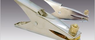
- hose holders for welding machines;
- grinding machines.
The functional diagram of the welding process looks like this:
As a result, standards are documents that collect all the necessary data to ensure repeatability of welding during its production. They also define the welding technology certification procedure necessary for preparing a welding process flow sheet for a specific welded product.
Peculiarities
At large production associations, engineers are involved in drawing up technological maps. In small enterprises, welders do this work themselves. Regardless of the identity of the compiler, the work begins with a careful analysis of the material that needs to be welded.
It is the material that determines the choice of the type of welding equipment, consumables and operating parameters. If the metal was initially analyzed correctly, then there will be no surprises in the work, and the final result will be of high quality.
Each technological map is assigned an original code. It is needed to identify the map among other archival materials. This number is recorded in the technical documentation for the finished structure. The map is signed by the specialist who compiled it.
Purpose of documents when preparing a welding process map
The unified system of technical documentation contains requirements and instructions for the preparation of technological documents, which include special-purpose documents - route maps, operational and technological processes. Guiding documents are prepared for each industry area. For example, such a document for RAO Gazprom describes welding, repair and restoration procedures on gas pipelines. It includes requirements for the selection of pipes, their assembly, materials, welding of joints, processing of welded joints, etc. Methods of certification, rejection and control, welding technologies, safety precautions, etc. are provided.
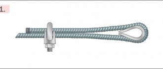
Let us consider, as an example, a typical technical process for welding flanges to pipes.
Typical process for welding flanges to pipe ends
A commonly used connection method is flanges. They look like flat parts of different shapes, in which special holes are made for attaching pipes. With their help, pipelines for various purposes and long building structures are assembled. They connect pipes tightly and tightly, providing flexibility in servicing a variety of joints. In addition, they connect the pipe to various equipment and valves.
Relief flanges are often added to a piping system to allow for regular maintenance of the system while it is running. For this purpose, flanges are welded onto the ends of the pipes, which are then bolted together using sealing gaskets. Such additional inserts into the pipeline system allow you to connect various equipment and devices and create additional connection systems.
Flanges can be classified in different ways, for example:
- by connection type;
- by the type of flanges themselves;
- based on temperature values and pressure;
- according to the materials used.
For the manufacture of flanges, carbon, low-alloy, stainless steels and combinations of exotic materials are used.
The use of flanges is quite common. Therefore, a number of standard technical processes have been developed that are used in the procedures for welding flanges to pipes.
Typically, the welding technique is determined by the required amount of play (gap) in the joints created.
- If there is no play, the technique of deep welding the edge of the pipe is used (technique - into a boat).
- Backlash over 1.5 mm is a technical technique of transverse oscillatory movements of the electrode itself, performed at a certain angle to the axial plane of the pipe.
- The backlash is 4-5 mm - fillet weld method.
The flanges are welded on both sides to obtain a reliable connection. This takes into account the type of structure and requirements for fastenings.
Note that underground pipelines do not use flanged connections, as flanges are the most common source of leaks and fires.
Structural elements
It is very important to approach the structure of the assembly and welding shop correctly. This is a manufacturing facility in which various operations are carried out using a wide range of different materials.
In addition to the main workshop, the production structure should include storage facilities: for metal, for consumables.
In the procurement department, the metal is prepared for work: cutting to specified dimensions, cleaning, grinding, etc. Next, the products are delivered to an intermediate warehouse, where blanks are assembled by item.
Then comes the main workshop, where parts and components are assembled and welded into a single structure. The last department in the structure is the finished products warehouse.
For obvious reasons, this cannot be organized in small welding shops, but this is not necessary. For example, an intermediate warehouse is of no use here, the same applies to the procurement workshop.
As practice shows, all operations are usually carried out in one room. And the finished products are either stored outside under a canopy, or delivered right there to the customer’s hands.
Description of the structure with warehouses - a fairly large complex that can be located under one roof or in different buildings. In such conditions, it is impossible to do without a well-thought-out organization of logistics that allows you to save on vehicles.
In new industries, they try to arrange welding shops on a block or modular basis. The entire structural chain is located in line with the necessary sequence of movement, from raw materials to finished products.
The attitude of consumers towards welding shops is almost unambiguous - it is a dusty room in which people work in soiled overalls. But you shouldn’t think this way about all workshops.
The new requirements and rules represent a new approach to the competent organization of work, where, first of all, the emphasis is on the person, on his professionalism, on the conditions in which he works. The result largely depends on this.
Welding of metal structures and process maps
Metal structures – metal structures is a generally accepted designation for products made of metals and alloys. For example, parts made of profiled metal in mechanical engineering, load-bearing steel frames of buildings in construction.
If at the beginning of the last century parts cast from cast iron were usually used, modern ones are created from steel or light alloys, such as aluminum. Their advantage:
- ease;
- corrosion resistance (galvanized or aluminum alloys);
- ease of production;
- volumetric strength, rigidity;
- decorativeness;
- installation speed.
Welding is one of the most important and widely used methods of joining metal structures. This process is significantly less expensive than screws and rivets and is more reliable than soldering or gluing.
Welded parts acquire durability properties, are reliable, easy to repair and convenient to manufacture.
It is impossible to simultaneously combine welding and riveting procedures in one structure due to different attitudes to loads. Welded structures are preferable to riveted or glued ones due to lower production costs, material savings, greater reliability when creating tight seams, etc.
The disadvantages are caused by the formation of defects in the seams due to the occurrence of internal stresses due to temperature changes and poor-quality welding.
There are many types of joining individual parts by welding. In each specific case, its own type and method are selected, for which a technological map for welding metal structures is drawn up.
Based on the nature of the requirements for the welded product, materials, component geometry, type of weld, and technique are selected.
Welding of metals is regulated according to a number of physical, technical and technological parameters. The physical criterion includes three main classes - mechanical, thermomechanical, arc welding.
For example, manual electric arc welding is a type of electric welding often used in practice, optimal for welding mild and alloy steels, stainless steel, cast iron, and a number of non-ferrous metals. Obviously, any type of arc welding requires its own process map.
Ventilation system
Ventilation of the welding shop is the most important component and one of the main requirements for organizing welding shops. With its help, heavy gases from the melting of metals and combustion of electrode rod coatings are removed from the welder’s workplace.
Many people make the mistake of installing a probe above a large workbench, which is connected to the general ventilation system by pipes or corrugations. The optimal and effective option is to install a side gas outlet so that they do not rise above the level of the workpieces being welded.
It is very important to make an accurate calculation of the ventilation system to ensure maximum air extraction from each workplace. It is better to install the fan outside the workshop. This will be especially true if the welding shop is organized in a garage.
A small room without ventilation will become a place where it will be impossible to stay without a respirator or gas mask. And the SES will not give permission to operate such a poorly equipped workshop. Therefore, it is very important not only to install a ventilation system, but also to correctly calculate the characteristics of the fan, especially the power of the device .
Plus, distribute the air ducts correctly so that they do not interfere when moving large parts. This means that you will have to make a drawing with the condition of the correct arrangement of all elements of the system.
Functional diagram of the welding process
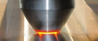
The rod electrode (diameter 1.5-10 mm) is fixed in electrode holders. The contact of the electrode with the metal surface causes an electrical closure and heating of the end of the electrode. When the electrode is moved 3-5 mm from the metal, an arc discharge occurs, which maintains an electric current. Intense local heating occurs, causing the part to melt. Metal is added to this melt from the end of the electrode. A joint “welding pool” is formed. The welding method, the shape of the electrodes and the weld, as well as all the subtleties of the process are recorded in a pre-compiled welding process map.
A certified welder, strictly following the technological map, monitors the constancy of the arc gap when connecting the welded edges, as well as the bead-seam created during crystallization of the molten metal.
Here 1.Orientation of welding process; 2. Shielding shell of the electrode; 3.Wire added as a melting material; 4. Gas protecting from air atmosphere; 5. Welding pool; 6. Seam that occurs during work; 7. Part to be welded.
Working with a non-consumable tungsten electrode often requires the addition of a wire additive. An inert gas is introduced into the working area to protect against impurities from the air. This method is characterized by the possibility of precise control for both manual welding and mechanized processes.
Welding of metal structures allows various types of joints of parts: butt, corner, lap and tee.
Groups of different types of welds are distinguished:
- By position in space - below, horizontally, vertically and on the ceiling.
- Regarding the applied voltage - from the flanks, from the ends, in combination, oblique.
- By length - continuous or not.
- According to the degree of roundness - smooth, convex or concave.
- By type of joint - at the joint or at an angle (roller).
All this diversity is taken into account when writing a technological map for welding metal structures.
The map begins with a description of the possible scope of application. It details the types of metal structures to which this technology is applicable, describes the location of parts and angles of fastenings. The temperature regime is determined.
The core of the technical map is the welding route and its technical characteristics. It is divided into sections:
- Initial preparation of work and rules for its implementation.
- Types of work.
- Sequence of stages.
- Schemes, design drawings, their descriptions for each process.
- Safety precautions and working conditions.
- Number and qualifications of certified workers, duration of work.
- Consumables, their quantity.
A clearly developed route of the technological process makes it possible to estimate in advance technical and material costs, work time and economic efficiency.
The final section of the technical map is the economic calculation of the necessary material and human resources.
The technological map for welding steel pipes is identical to the above map in form, but differs slightly in information.
This document includes the following information:
- The scope of applicability of the technical map, for which objects it works.
- General provisions and recommendations for carrying out work.
- Description of technology and requirements for organizing the work process.
- Work quality control.
- Working conditions and safety precautions.
- List of used regulatory documentation and GOSTs.
- Technical maps for each type of welding.
Instructions are prepared for each operation separately, in their entirety and sequence, for preliminary inspection of welded objects for malfunctions, cleanliness and defects. It is mandatory to follow work safety and fire safety requirements when preparing the work site.
All actions must be performed in accordance with the operational flow charts included in the flow chart of the process as a whole. The quality of the work is determined by the seam inspection methods listed there.
As an example, we give a technical map for pipeline welding.
Practical recommendations
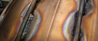
Seams can be made in one pass, and then such a solder is called single-layer. If the weld was formed by several passes of electrodes, then it is a multi-layer weld. The joint formed during single-layer welding is not ductile and looks quite rough. This is due to the fact that the metal in the area where the connection was made was very overheated. But at the same time, it is the seam obtained in one pass that is economical and productive.
Multilayer welding forms a neat seam as a result of the fact that each pass heats only a certain area of the metal. In this case, a thin seam is made, which increases slightly during the second pass. In multilayer welding, the layers can be arranged in a sequential or cascading manner, in a slide. With the sequential method, each of the following layers is applied to the previous one only after a complete pass along the entire seam has been completed.
The cascade method and the “slide” are used when welding thick layers of metal. With any of the multilayer welding methods, one pass must be performed especially carefully; the strength of the resulting joint depends on this.