Structure of carbon steels
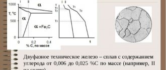
⇐ PreviousPage 7 of 8Next ⇒Steels are alloys of iron and carbon containing from 0.02% to 2.14% carbon. With a carbon content of up to 0.006%, the alloys are single-phase and have a ferrite structure, for example, electrolytic iron.
Alloys containing from 0.006% to 0.02% carbon are called technical iron (Figure 4.7).
An increase in carbon content due to its low solubility in ferrite causes the appearance of a second phase - tertiary cementite. With a carbon content of up to 0.025%, structurally free cementite precipitates mainly along the boundaries of ferrite grains. This significantly reduces the ductility and toughness of steel, especially if cementite is located
dies in chains or forms a network around ferrite grains.
When the carbon content increases above 0.025%, pearlite is formed in the steel structure; at the same time, even before 0.10 - 0.15% C, inclusions of structurally free (tertiary) cementite appear in the steel. With a further increase in carbon content, tertiary cementite becomes part of perlite.
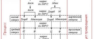
The transformations that occur in steels during the process of heating and cooling can be monitored using the left side of the phase diagram (Figure 4.6).
Based on their microstructure, steels are divided into hypoeutectoid, eutectoid and hypereutectoid (Figures 4.8, 4.9, 4.10). Steels with a carbon content of 0.02 to 0.8% are called hypoeutectoid; with a content of 0.8% carbon - eutectoid; with a content from 0.8% to 2.14% - hypereutectoid.
As follows from the Fe-Fe3C diagram, at room temperature in equilibrium, the microstructure of hypoeutectoid steel consists of ferrite and pearlite (Figure 4.8). The quantitative relationship between the structural components (F and P) in hypoeutectoid steels is determined by the carbon content. The closer the carbon content is to the eutectoid concentration, the more pearlite there is in the structure.
The microstructure of eutectoid steel (0.8% C) consists only of pearlite (Figure 4.9). Formed from austenite during cooling of U8 steel (PSK line). The structure of perlite due to its significant dispersion (fine grain) can be distinguished in detail only at relatively high magnifications (×600).
The microstructure of hypereutectoid steel (Figure 4.10) consists of pearlite and secondary cementite. It is formed in steel U9-U13 from austenite during cooling. A cementite network begins to form on the ES line, pearlite - on the PSK line. The maximum amount of structurally free cementite (~ 20%) will be in an alloy with a carbon content of 2.14%.
also light color, a thin section etched with a 4% solution is required
rum of nitric acid, re-grind, re-polish and re-
etch with a solution of sodium picrate, which colors cementite dark
color.
Based on the microstructure of hypoeutectoid steel, one can approximately determine the carbon content in it, for which it is necessary to approximately determine the area (in percent) occupied by pearlite, due to the fact that a very small amount of carbon is dissolved in ferrite, it can practically be assumed that all carbon is contained in hypoeutectoid steel is in perlite.
C =100⋅ 0.8 P S,
where C is the concentration of carbon in the alloy, in percent;
П S is the visible part of the microstructure area occupied by pearlite
in percentages.
According to the quantitative ratio of pearlite and ferrite, according to GOST 8233-56 Steel. Microstructure standards, ferrite-pearlite structures are classified on a ten-point scale (Table 4.1). The assessment is made visually at 100-fold magnification based on the average area occupied by perlite on a microsection.
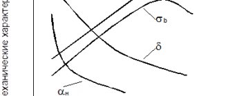
Dependence of the mechanical properties of carbon steels on
Carbon content
Changes in carbon content cause changes in the structure of steel, which, in turn, has a decisive effect on the properties of steel.
According to the phase diagram, the structure of steel in the equilibrium state is a mixture of ferrite and cementite, and the amount of cementite increases in proportion to the carbon content. Ferrite is low-strength and ductile, cementite is hard and brittle. Therefore, an increase in cementite leads to an increase in hardness, strength and a decrease in ductility.
renders secondary cementite forming a brittle framework around the grains
perlite. Under load, this frame breaks prematurely, causing
decrease in strength and ductility. Because of this, hypereutectoid steels are used
changed after special annealing with a structure of granular pearlite, distinguished
resulting from lamellar pearlite with lower hardness and greater ductility
sticism.
Carbon changes the technological properties of steel: machinability, pressure, weldability. An increase in carbon content leads to a decrease in machinability. Steels containing 0.3 - 0.4% C have the best machinability.
With an increase in carbon content, technological plasticity decreases - the ability to deform in a hot and, especially, in a cold state. For complex cold forming, the carbon content is limited to 0.1%.
Carbon makes steel difficult to weld. Low-carbon steels have good weldability. For illustration, Figure 4.11 shows a graph of the mechanical properties of steel versus carbon content.
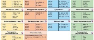
Classification and marking of carbon steels
Carbon steels are divided into low-carbon steels up to 0.25% C, medium-carbon (0.3 - 0.6% C), high-carbon (more than 0.6% C). Based on their application, carbon steels are divided into structural and tool steels. Structural steels are classified into conventional steel
new quality and high quality.
Structural carbon steel of ordinary quality is designated by the letters St, followed by a number from 0 to 6, indicating the
measures of steel grade (carbon content increases with increasing number),
for example: St1, St2, …, St6. The higher the number, the higher the strength and hardness.
strength, but lower ductility (Table 4.2). The most flexible and the least
hard ones - St0, St1, St2 - are used for the production of roofing sheets, fasteners
nal products; the hardest and most durable steel of this group - St6 - is used
found, for example, in the production of rails and springs. Steel of ordinary quality
products are produced in the form of rolled products (rods, beams, sheets, angles, channels and
etc.).
High-quality carbon steels are characterized by a lower content of harmful impurities and non-ferrous impurities than ordinary steels.
thallus inclusions.
High-quality steel is marked with a two-digit number indicating the average carbon content in hundredths of a percent. Low-carbon steel grades 08, 10, 15, 20, 25 are used for the manufacture of hardware and parts that do not require high strength. Medium-carbon steels 30, 35, ..., 55 are distinguished by greater strength and lower ductility than low-carbon steels. High-carbon steels of grades 60, 65, ..., 85 have great hardness and strength and are used for the manufacture of responsible
specific machine parts.
High-quality tool steels are marked with the letter U and a number indicating the carbon content in tenths of a percent: U7, U8, etc. High-quality tool steels are marked in the same way as
high-quality, but at the end of the stamp they put the letter A: U7A, U8A - U12A.
Work order
4.8.1 Study the state diagram of Fe – Fe3C transformations that occur
walking in iron-carbon alloys when cooled.
4.8.2 Familiarize yourself with the structural components of iron-carbon
hard alloys. Find on the state diagram the regions of existence of these
structures.
4.8.3 Obtain microsections of samples of various steels from the laboratory assistant. Use a metallographic microscope to study the structural
components of iron-carbon alloys. Determine the type of alloy: steel
(hypoeutectoid, eutectoid, hypereutectoid).
4.8.4 Sketch all viewed structures indicating phase and
structural components. Sketch the microstructures in squares of size
rum 50 × 50 mm. The main thing when sketching a microstructure is to capture the characteristics
tern features of the microstructure and convey them in the drawing. No need-
ability to convey a photographically accurate image in a drawing. Phases and
indicate structural components with arrows, write their names in the margins
new
Contents of the report
4.9.1 Purpose of the work.
4.9.2 Brief description of the structural components of iron-carbon
hard alloys.
4.9.3 Drawing of the phase diagram of Fe – Fe3C.
4.9.4 Diagrams and description of the microstructure of steels and cast irons.
4.9.5 Conclusions on the work. The findings indicate the influence of content
carbon on structure and mechanical properties; influence of graphite shape
inclusions and structure of the metal base on the properties of cast iron.
4.10 Test questions
4.10.1 Which iron-carbon alloys are classified as technical
iron, steel and cast iron?
4.10.2 What are the phase and structural components of the Fe-C system?
Characteristics of structural components.
4.10.3 Which of the structures of iron-carbon alloys is mechanical?
a mixture of ferrite and cementite?
4.10.4 What is ledeburite?
4.10.5 How are steel and cast iron classified according to their structure?
Appendix A
(informative)
Acquiring skills in working with the iron-carbon phase diagram
Initial data:
The alloy contains 0.7% carbon. Set temperature 600 °C.
| Numbers of temperature intervals | Temperature limits of intervals, °C | Carbon concentration in phase states, % | Structural composition | System Variability |
| upper limits | lower limits | phase name | at the upper limit of the temperature range | at the lower limit of the temperature range |
| J A | 0,7 0,2 | 2,25 0,7 | F+A | |
| A | 0,7 | 0,7 | A | |
| A F | 0,7 0,016 | 0,8 0,02 | A+F | |
| F A Fe3С | 0,8 0,02 6,67 | 0,8 0,02 6,67 | A+F+ P | |
| Ф Fe3С | 0,02 6,67 | 0,01 6,67 | F+P | |
| F - liquid, A - austenite, F - ferrite, P - pearlite, Fe3C - cementite |
Laboratory work No. 5
Iron-carbon diagram exercises *)
Goal of the work
Acquiring skills in working with state diagrams using an example
iron-carbon diagrams.
General information
Phase diagrams are graphical representations of the state of alloys. The properties of alloys are determined, first of all, by the composition of the phases and their quantitative ratio. Information about the composition and relationship of phase components can be obtained by analyzing the phase diagram. Knowing the phase diagram, it is possible to present a complete picture of the curve
Stallization of any alloy, formation of its structure. Diagram of co-
standing allows you to evaluate the properties of alloys and find optimal parameters
technological processes such as casting, thermal and chemical
heat treatment, draw a conclusion about the possibility of pressure treatment
niem, etc.
Work order
5.3.1 Receive an assignment from the teacher to complete the work (in the first
at the second stage - the concentration of carbon in the alloy, at the second - the temperature of the alloy
va).
5.3.2 Describe the process of crystallization of an alloy of a given composition (stage
first). As you work, fill out Table 5.1.
Table 5.1 – Phase and structural composition of the alloy at temperatures
intervals
| Numbers of temperature intervals | Temperature limits of intervals, °C | Carbon concentration in phase states, % | Structural composition | System Variability |
| upper limits | lower limits | phase name | at the upper limit of the temperature range | at the lower limit of the temperature range |
⇐ Previous7Next ⇒
Conflicts in family life. How can I change this? It is rare that a marriage and relationship exists without conflict and tension. Everyone goes through this...
WHAT HAPPENS WHEN WE FIGHT Without understanding the differences that exist between men and women, it is very easy to lead to a quarrel...
What does the IS operation and maintenance department do? Responsible for the safety of data (copying schedules, copying, etc.)…
WHAT AND HOW THEY WRITTEN ABOUT FASHION IN MAGAZINES AT THE BEGINNING OF THE XX CENTURY The first issue of the Apollo magazine for 1909 began, in fact, with a policy statement from the magazine’s editors...
Didn't find what you were looking for? Use Google search on the site:
Features of obtaining the structure of hypoeutectoid steel
Content
- 1. Structure of hypoeutectoid steel
- 1.1 phase transformations of steel
- 2. Obtaining the structure of hypoeutectoid steel
- 2.1 Full annealing
- 2.2 Partial annealing
- 2.3 Normalization
- 2.4 Heating
- List of used literature
1. Structure of hypoeutectoid steel
The structure of hypoeutectoid steels at all temperatures below 723 consists of ferrite grains and pearlite grains, and hypereutectoid steels - of pearlite grains and cementite grains. The structure of steel, containing 0–8% carbon and called eutectoid, consists only of pearlite grains at temperatures below 723. At room temperature, the structure of hypoeutectoid steel consists of excess ferrite, released from austenite between the GS and PS lines, and pearlite, which was formed during the eutectoid transformation. With increasing carbon content, the amount of pearlite increases and the amount of ferrite component decreases. In eutectoid steels (about 0-8% C), all austenite is converted to pearlite. C) due to a decrease in the solubility of carbon in gamma iron (line ES), secondary cementite is released from austenite. At a temperature of 723 C, a eutectoid transformation occurs. As a result of this transformation, the steel acquires a structure consisting of pearlite grains and a network of secondary cementite. The thickness of the mesh increases with increasing carbon content. In alloys containing 2 06 - 4 3% C (hypoeutectic cast irons), after separation of austenite from a liquid solution at a temperature of 1147 C (ECF line), a eutectic transformation occurs (see Eutectics) Zhs - AE C, a mechanical mixture of austenite and cementite - ledeburite. In accordance with the ES diagram line, excess carbon is released from austenite in the form of secondary cementite, and at a temperature of 723 C, austenite turns into pearlite.
When eutectic cast iron crystallizes (about 4-3% C), the entire liquid solution turns into ledeburite. In hypereutectic cast irons (4 3 - 6 67% C), primary cementite crystallizes from the melt in the CDF region; their structure consists of ledeburite and primary cementite. Above temperature 723 C, ledeburite is a eutectic mixture of austenite and cementite, and the composition of austenite, depending on temperature, is described by the SE line. Below the temperature of 723 C, ledeburite is a eutectic mixture of eutectoid pearlite and cementite. When underheated, residual ferrite or martensite of uneven structure is observed in the structure of hypoeutectoid steels. When overheated, needle-shaped martensite appears, the size of the needles of which is larger, the more significant the overheating was during the austenitization process. The most objective method for assessing the optimal heating regime is etching the martensitic structure to identify former austenite grains. Full annealing is used to recrystallize the entire structure of hypoeutectoid steel in order to refine the grains of the ferrite and pearlite components and relieve residual stresses. Thus, as a result of secondary crystallization, the structure of hypoeutectoid steels consists of ferrite grains and pearlite grains
1.1 phase transformations of steel
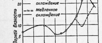
Transformation of pearlite (ferrite-cementite mixture) into austenite. It occurs when any steel is heated above the Ac1 point by at least one degree. In addition, with further heating in hypoeutectoid steels in the temperature range Ac1 - Ac3, excess ferrite dissolves in austenite. Above the Ac3 point, the steels are in a single-phase austenitic state. Moreover, the higher the temperature, the larger the austenite grain. To obtain fine austenitic grains, steel must be heated only 30 - 50 °C above the Ac3 point. Transformation of austenite into pearlite. This process occurs in the upper temperature range (Ac1 - 550 °C) of the isothermal transformation diagram of supercooled austenite. For example, at cooling rates V1 and V2, austenite decomposes with the formation of pearlite structures in the temperature range ac and a'c', respectively. It should be borne in mind that the higher the cooling rate, the lower the temperature range of austenite decomposition, the more dispersed and harder the mixture of ferrite and cementite is obtained . The decomposition products of austenite (pearlite, sorbite, trostite) have a lamellar structure and differ from each other in the degree of dispersion of ferrite and cementite plates.
2. Obtaining the structure of hypoeutectoid steel
The structure of hypoeutectoid steel is formed as a result of the decomposition of austenite during cooling, consists of ferrite and ferrite-cementite mixture (pearlite), the dispersion of which depends on the degree of supercooling, and as the temperature decreases, the transformation has increasing dispersion (granular pearlite, plastic pearlite, sorbitol, -osteitis). The amount of pearlite and ferrite depends on the carbon content in the steel; with a content of <0.02% C, the structure consists of ferrite; with a content of 0.8% C, the structure consists of pearlite alone.
The main factor on which the microstructure of steel depends on type 2 annealing is the degree of overcooling of austenite. Types of annealing of the 2nd type differ mainly in the methods of cooling and the degree of overcooling of the austenite, as well as the position of the heating temperatures relative to the critical points.
The required degree of supercooling of austenite is achieved either by continuous cooling or by isothermal treatment.
The figure, using hypoeutectoid steel as an example, schematically shows the cooling modes corresponding to the main types of annealing of the 2nd type: full (1), isothermal (2), normalization (3), annealing (normalization) and patenting (4).
When annealing or normalizing to obtain fine grains, it is necessary to carefully monitor the thermocouple readings and avoid overheating, i.e. a strong increase in temperature compared to the normal annealing or normalization temperature. When overheated, initially small grains of austenite will begin to grow and become large (see Fig. 93), and from large grains of austenite, upon subsequent cooling, large grains of ferrite and pearlite will be obtained. Steel overheated during annealing will be the same coarse-grained as it was before annealing.
Scheme of changes in the structure of hypoeutectoid steel during annealing and normalization.
2.1 Full annealing
During annealing, the steel, after being heated above the critical point, is slowly cooled along with the furnace. Carrying out annealing of the 2nd kind is based on the use of phase transformation, in contrast to annealing of the 1st kind, based on recrystallization, removal of macrostresses and other structural changes not necessarily associated with phase transformations.
To carry out complete annealing, hypoeutectoid steel is heated to temperatures 20 - 40 ° C above the Ac3 point.
Figure 2. Heating temperature of steels for type 2 annealing:
1 - complete annealing;
2 - incomplete annealing;
3 - spheroidizing annealing;
4 - normalization.
Cooling during annealing is carried out at such a low rate that the austenite decomposes at a low degree of supercooling. Since austenite in alloy steels is more prone to overcooling (see figure Schematic diagrams of isothermal decomposition of austenite), they should be cooled during annealing at a lower rate than carbon steels.
If carbon steels can be cooled during annealing at a rate of 200 degrees/hour, then alloy steels can be cooled at a rate of 100-30 degrees/hour. The cooling rate during annealing can be adjusted by cooling the furnace with the door closed or open, with the heating completely or partially turned off, and transferring the charge into a special slow cooling chamber.
Figure 3. Microstructure of hypoeutectoid steel. X 100:
a - Widmanchett structure of cast steel;
b - the same steel after complete annealing.
If the temperature at the end of hot forming (forging, rolling) is too high, then large austenite grains have time to grow, and if the temperature is too low, then a stitch structure appears.
Figure 4. Stitch structure of hypoeutectoid steel:
a - X 70;
b - X 300.
The weld has the same structural flaws as cast steel, and adjacent to the zone of the cast structure there is a zone of steel that is overheated in the solid state. During heat treatment operations, overheating of the steel is possible. For example, during homogenization annealing, steel must be heated to temperatures of 1100 - 1200°C, at which large austenite grains grow.
To eliminate these structural defects that arose during casting, hot deformation, welding and heat treatment, it is necessary to carry out complete phase recrystallization. When heated to the temperature Ac3+ (20 - 40°C), small austenite grains are formed, from which, upon cooling, a uniform and fine structure consisting of ferrite and pearlite is formed.
Sometimes a single annealing is not enough to correct the steel structure. This is explained, firstly, by the fact that the austenite grains formed during heating are in orientational connection with the original Widmanstätten structure or the structure of bainite and martensite formed during the heating of castings, welds and hot rolled alloy steels in air. With such an initial structure, conventional annealing does not correct the coarse-grained fracture (see Formation of austenite during heating). Secondly, during hot deformation, slag and sulfide inclusions are pulled along the ferrite strips. During normal heating to Ac3 + (20 - 40°C), these inclusions do not dissolve in austenite and, upon subsequent cooling, orient the precipitated ferrite, i.e. stitching cannot be eliminated by conventional annealing.
In the cases considered, double annealing can be used: first at elevated and then at normal temperature.
The first high-temperature annealing (above the Chernov b point) is necessary for the development of primary recrystallization of austenite, eliminating its orientational bonds with the original crystallographically ordered structure (see Formation of austenite during heating), as well as for the dissolution of elongated slag and sulfide inclusions. The second annealing at normal temperature eliminates the overheating structure from the first annealing. The purpose of conventional full annealing, which refines the grain, is the opposite of the purpose of annealing, which enlarges the grain. Annealing for coarse grains with heating up to 950 - 1100°C is used for soft low-carbon steels to improve cutting machinability. Such steels produce viscous, difficult-to-separate chips and are capable of welding to the cutting tool, which makes the surface rough.
The improvement of the surface quality and greater fragility of low-carbon steel chips is facilitated by a structure with large colonies of lamellar pearlite, which is obtained by high-temperature annealing, which increases the grain.
2.2 Partial annealing
Incomplete annealing of hypoeutectoid steel is carried out by heating to temperatures above Ac1, but below Ac3. This annealing is used to a limited extent for hypoeutectoid steels. At the incomplete annealing temperature, excess ferrite does not disappear. Consequently, incomplete annealing cannot eliminate the above-mentioned steel defects, which are associated with the undesirable size and shape of excess ferrite. Incomplete annealing of hypoeutectoid steel is used to soften it before cutting, since soft pearlite is formed as a result of the eutectoid transformation during incomplete annealing. Incomplete softening annealing saves time and reduces processing costs.
2.3 Normalization
Normalization is a heat treatment process that involves heating steel above the upper critical point Ac3, holding until austenite (fine-grained) is completely formed, and cooling in still air. Normalization differs from complete annealing by accelerated cooling (curve 2 in Figure 1). In this case, the decomposition of austenite occurs at lower temperatures (section a'c') than during annealing (section ac). The grain of normalized steel is finer and its hardness is higher than that of annealed steel.
2.4 Heating
Having heated the hypoeutectoid steel to a temperature slightly higher than the A3 temperature and kept it at this temperature for some time, the steel is cooled:
1) either slowly - with the oven, i.e. annealing is carried out;
2) or more quickly - in air, i.e. perform normalization.
Since normalization produces faster cooling than annealing, ferrite and pearlite grains in normalized steel turn out to be smaller, even finer than the original austenite grains: from one austenite grain two, three or even several ferrite grains and several pearlite grains are obtained . During annealing, the grains are slightly larger than during normalization. But in both cases, i.e. both during annealing and normalization (if, of course, they are carried out correctly), the structure of the steel turns out to be fine-grained
Something else is more significant. With faster cooling (normalization), the structure of the ferrite-cementite mixture (perlite) becomes more dispersed (crushed), and essentially, instead of perlite, the structure of normalized steel has sorbitol. And since sorbitol, precisely because of its higher dispersion, has higher strength, the values of the tensile strength, yield strength, hardness and even impact strength of normalized steel are slightly higher than the values of the same properties of annealed steel, as can be seen from Table. 7.
The structure of sorbitol becomes more dispersed, and the mechanical properties are higher, the higher the temperature it is cooled from. This is why normalization temperatures are often chosen higher than annealing temperatures. Maybe in this case it makes sense to increase the normalization temperatures even more? Indeed, in this case, it must be assumed that the structure of sorbitol will be even more dispersed, and the mechanical properties will become even higher. But this is half wrong: indeed, the higher the normalization temperature, the more dispersed the structure of sorbitol will be, but the properties will nevertheless not increase, but decrease: overheating will begin to affect it, and large grains will negate the advantages of the dispersed structure of sorbitol.
structure hypoeutectoid steel annealed
List of used literature
1. Tushinsky, L.I. Methods of materials research / L.I. Tushinsky, A.V. Plokhov, A.O. Tokarev, V.N. Sindeev. - M.: Mir, 2004. - 380 p.
2. Lakhtin, Yu.M. Materials Science / Yu.M. Lakhtin. - M.: Metallurgy, 1993. - 448 p.
3. Fetisov, G.P. Materials science and metal technology / G.P. Fetisov, M.G. Karpman et al. - M.: Higher School, 2001. - 622 p.
4. Evstratova, I.I. Materials Science / I.I. Evstratova and others - Rostov-on-Don: Phoenix, 200 - 268 p.
5. Markova, N.N. Iron-carbon alloys/ N.N. Markova. — Orel: Orel State Technical University, 200 — 96 p.
6. Ilyina, L.V. Materials used in mechanical engineering: reference manual / L.V. Ilyina, L.N. Kurdyumova. — Orel: Orel State Technical University, 2007.15-20 pages
7. https://turboreferat.ru/metallography/dojevtektoidnaya-stal/137611-701138-page1.html
8. https://www.inmetal.ru/50-zakalka-doyevtektoidnyx-i-zayevtektoidkyx-stalej.html
mtomd.info
All alloys of the iron-cementite system are divided into two large groups according to their structural characteristics: steel and cast iron .
Marking of steels. Marking of carbon steels. Marking of alloy steels. Marking of tool steels.
A special group consists of alloys with a carbon content of less than 0.02% (point P), they are called technical iron . The microstructures of the alloys are presented in Figure 1. The structure of such alloys after the end of crystallization consists either of ferrite grains (Figure 1, position a), with a carbon content of less than 0.006%, or of ferrite grains and tertiary cementite crystals located along the boundaries of the ferrite grains (Figure 1 , position b), if the carbon content is from 0.006 to 0.02%.
Components of iron-carbon alloys. Phases of iron-carbon alloys. Processes during structure formation of iron-carbon alloys. Eutectoid transformation. Eutectic transformation. Iron-carbon diagram. Iron-carbon phase diagram. Iron-cementite diagram. Iron-cementite phase diagram.
Figure 1 - Microstructures of technical iron
a – carbon content less than 0.006%; b – carbon content 0.006…0.02%
Carbon steels are alloys of iron and carbon containing 0.02...2.14% carbon, which complete crystallization with the formation of austenite. They have high ductility, especially in the austenitic state. The structure of steels is formed as a result of recrystallization of austenite.
Carbon steels. Low carbon steel grades. High carbon steel grades. Medium carbon steels.
Figure 2 - Microstructures of steels
a – hypoeutectoid steel (F + P); b – eutectoid steel (lamellar pearlite); c – eutectoid steel (granular pearlite); g – hypereutectoid steel (P + Tsp)
Based on carbon content and structure, steels are divided into:
- hypoeutectoid (0.02% < C < 0.8%), ferrite + pearlite (F + P) structure (Figure 2, position a);
- eutectoid (C = 0.8%), pearlite structure (P), pearlite can be lamellar or granular (Figure 2, positions b, c);
- hypereutectoid (0.8% < C < 2.14%), structure pearlite + secondary cementite (P + CII), cementite network is located around pearlite grains (Figure 2, position u).
Based on the microstructure of the alloys, it is possible to approximately determine the amount of carbon in the alloy composition, taking into account the following: the amount of carbon in pearlite is 0.8%, in cementite - 6.67%. Due to the low solubility of carbon in ferrite, it is assumed that there is no carbon in it.
Diagram of the state of alloys of mechanical mixtures. Eutectic. Eutectic alloy.
Alloys of iron and carbon containing more than 2.14% carbon (up to 6.67%), which complete crystallization with the formation of eutectic (ledeburite), are called cast iron .
The presence of low-melting ledeburite in the structure of cast iron increases their casting properties.
Cast irons, which crystallize according to the iron-cementite phase diagram, are highly brittle. The color of their fracture is silvery-white. Such cast irons are called white cast irons .
Figure 3 - Microstructures of white cast irons
a – hypoeutectic white cast iron (P + L + CII); b – eutectic white cast iron (L); c – hypereutectic white cast iron (L + CI)
Based on the amount of carbon and structure, white cast irons are divided into:
- hypoeutectic (2.14% < C < 4.3%), structure pearlite + ledeburite + secondary cementite (P + L + CII) (Figure 3, position a);
- eutectic (C = 4.3%), ledeburite structure (L) (Figure 3, position b);
- hypereutectic (4.3% < C < 6.67%), structure ledeburite + primary cementite (L + CI) (Figure 3, position c).
The structure of hypoeutectic white cast iron contains secondary cementite, which is formed as a result of a change in the composition of austenite during cooling (along the ES line). In the structure, secondary cementite merges with cementite, which is part of ledeburite.
Crystallization of alloys. Crystallization of metals and alloys. Crystallization process. Crystallization of metals. Crystallization of steel. Crystallization of substances. Crystallization of pure metal. Crystallization temperature.
The phase composition of steels and cast irons at normal temperatures is the same; they consist of ferrite and cementite. However, the properties of steels and white cast irons differ significantly. Thus, the main factor determining the properties of alloys of the iron-cementite system is their structure.
Structure and properties of iron-carbon alloys
Technical hardware
. The structure of technical iron with a carbon concentration of 0.012% (Fig. 4.4) consists of light polyhedral grains of ferrite and tertiary cementite, which is located in the form of light inclusions along the boundaries of ferrite grains.
Ferrite is a plastic and soft component (800 HB, δ
= 40%).
Cementite is hard and brittle (8000 HB, δ
= 0%). The presence of tertiary cementite veins at the grain boundaries reduces the plasticity and toughness of the alloy.
Rice. 4.4. Technical (two-phase) iron
Become
. During the cooling process, ferrite is released from the austenite of hypoeutectoid steels (Fig. 4.5a). The temperature at which ferrite begins to precipitate is determined by the GS line (see Fig. 4.1).
The precipitation of ferrite leads to the enrichment of austenite with carbon. At 727 °C, the carbon concentration in austenite reaches 0.8%, and under these conditions a eutectoid reaction takes place
A0.8% → P0.8%(F+C).
Thus, the structure of hypoeutectoid steels at room temperature consists of ferrite, precipitated in the temperature range Ar3–Ar1 (GS and PS lines), and pearlite, formed at 727 °C.
In the structure of hypoeutectoid steel there is much more cementite than in technical iron, and this increases the hardness of the steel (Fig. 4.2).
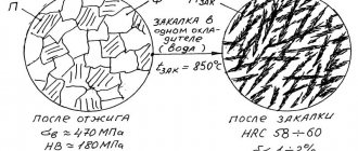
Steel with a carbon content of 0.8% has a pearlite structure and is called eutectoid steel. Pearlite most often has a plastic structure, in which cementite crystals alternate with ferrite crystals (Fig. 4.5b). An increase in carbon content increases the hardness and strength, but reduces the ductility of the alloy.
Rice. 4.5. Steel structures: a – hypoeutectoid steel, b – eutectoid steel, c – hypereutectoid steel
The structure of hypereutectoid steel is also formed from austenite. In the temperature range Arst – Ar1
(lines SE and SK) secondary cementite is released from austenite, which, as a rule, is located along the grain boundaries. At 727 °C, the carbon concentration in austenite will correspond to 0.8%, it decomposes with the formation of pearlite.
Thus, the structure of hypereutectoid steel at room temperature is pearlite and secondary cementite (Fig. 4.5c). The proportion of the cementite component has increased in comparison with previous alloys. Now cementite not only enters into pearlite (eutectoid), but also the hardness of steel increases to 3000 HB.
Cast iron.
White eutectic cast iron crystallizes at 1147 °C (see Fig. 4.1, ECF line) with the formation of ledeburite:
F4.3% C → L(A2.14% C + C6.67% C).
Cooling to 727 °C leads to a decrease in the carbon concentration in austenite to 0.8%. At 727 °C, austenite transforms into pearlite.
Thus, eutectic cast iron (Fig. 4.6b) at room temperature has the structure of ledeburite, consisting of pearlite and cementite. The main phase in white cast iron is cementite, therefore white cast iron is hard (6500 HB).
The structure of hypoeutectic cast irons (Fig. 4.6a) consists of pearlite, secondary cementite and ledeburite, and hypereutectic cast irons (Fig. 4.6c) - of ledeburite and cementite released from the liquid phase.
Rice. 4.6. Structures of white cast iron: a – hypoeutectic cast iron, b – eutectic cast iron, c – hypereutectic cast iron
The dependence of the properties of gray cast iron on the structure is much more complex than that of steel, since gray cast iron consists of a metal base and graphite inclusions. Therefore, to characterize the structure of gray cast iron, it is necessary to determine the size, shape, distribution of graphite, as well as the structure of the metal base (Fig. 4.7).
Rice. 4.7. Gray pearlite-ferritic cast iron
The fewer graphite inclusions, the smaller and more strongly isolated they are from each other, the higher the strength of cast iron with the same metal base.
Rice. 4.8. High-strength pearlite-ferritic cast iron
The metal base of gray cast iron SCh 15 with a carbon content of 3.1–3.6% (Fig. 4.7) consists of ferrite (white component) and perlite (dark component). Coarse or medium-plate graphite inclusions in the form of dark stripes cut the metal base. Therefore, such gray cast iron has low tensile strength and practically zero ductility: σB
= 150 MPa,
δ
= 0.5%. Hardness is determined by the structure of the metal base and corresponds to 1630–2290 HB.
Rice. 4.9. Malleable ferritic cast iron
High-strength cast iron, unlike gray cast iron, has graphite inclusions that are spherical rather than lamellar. This cast iron has higher mechanical properties. The structure of HF 45 (Fig. 4.8) with a carbon content of 3.3–3.5% consists of ferrite (light component), pearlite (dark component) and spherical graphite (dark rounded inclusions) (Fig. 4.8). Tensile strength σВ
= 450 MPa, relative elongation
δ
= 5%. Hardness is determined by the metal base and corresponds to 1700–2070 HB.
Malleable cast iron has flake-shaped graphite. This provides good mechanical properties. The structure of CN 35–10 with a content of 2.4–2.8% C consists of light grains of ferrite and flake graphite (Fig. 4.9).
The ferritic metal base provides low hardness (1490–1630 HB). Strength of cast iron σB
= 350 MPa, relative elongation
δ
= 10%.
Work order
1. Draw a diagram “ Fe - Fe3C
» indicating transformation temperatures and carbon concentrations for characteristic points.
2. Indicate the phases and structural components in different areas of the diagram.
3. Prepare the metallographic microscope for use. The study of the microstructure of iron-carbon alloys is carried out at the necessary magnifications of a metallographic microscope.
4. View the proposed thin sections, select the most characteristic areas and sketch them in the report. Determine the type of alloy, approximate or exact carbon content, basic mechanical properties.
3. Test questions
1. Determination of ferrite, austenite, cementite, graphite.
2. Determination of perlite, ledeburite.
3.What is technical iron, steel, cast iron?
4. What is the difference in the structure of white cast iron from gray, high-strength, malleable cast iron?
5. How is gray, malleable, high-strength cast iron produced?
6. How and why does the hardness of alloys change as the carbon concentration increases?
7. Based on the microphotograph proposed by the teacher, determine the type of alloy (commercial iron, steel, cast iron), structural and phase composition, and limits of carbon content.
8. Using the “Iron - cementite” diagram, describe the processes occurring in steels and white cast irons during crystallization.
Theoretical part. 1.1 Microstructure of technical iron
1.1 Microstructure of technical iron
The microstructure of commercial iron and carbon steels is characterized by the lower left part of the Fe-Fe3C phase diagram (Figure 1).
Alloys with a carbon content of up to 0.02% are called technical iron (Figure 2); the solubility of carbon in a-iron is variable (see PQ line). With decreasing temperature, the solubility of carbon in a-iron decreases. At a temperature of 727 °C, 0.02% carbon dissolves in a-iron, and at room temperature 0.006%. In this regard, iron alloys with a carbon content of up to 0.006% have only a ferrite
, i.e. solid solution of carbon in a-iron.
In alloys with a carbon content from 0.006 to 0.02%, due to a decrease in the solubility of carbon in a-iron with decreasing temperature, cementite
called
tertiary
. At room temperature, the structure of such alloys consists of ferrite and tertiary cementite, which is located along the boundaries of ferrite grains (Figure 2).
The maximum amount of tertiary cementite in the alloy is approximately 0.3%. However, even such a small amount of tertiary cementite imparts low plastic properties to low-carbon steel, i.e. leads it to embrittlement (due to the location of brittle shells around ferrite grains). To eliminate this phenomenon, a special heat treatment is carried out, as a result of which tertiary cementite is released in the form of dispersed particles evenly distributed throughout the grain.
1.2 Microstructure of steel
Iron-carbon alloys with a carbon content from 0.02 to 2.14% are called steels . Alloys with a carbon content from 0.02 to 0.8% are called hypoeutectoid
steels;
from 0.8 to 2.14% - hypereutectoid
.
Figure 1 – Fe-Fe3C phase diagram
A
b
a - ferrite; b - ferrite + tertiary cementite
Figure 2 – Microstructure of technical iron and its schematic representation
An alloy with a carbon content of 0.8% is called eutectoid
steel.
The microstructure of eutectoid steel is a mechanical mixture of ferrite (FeaC) and cementite (Fe3C), which is obtained as a result of the decomposition of a solid solution of carbon in g - iron - austenite
(FegC) with a carbon content of 0.8% at T = 727 °C (see Fig. point “S” on the Fe-Fe3C diagram).
This mechanical mixture is called perlite
, because... When etching a thin section of eutectoid steel, the surface has a pearlescent tint.
The pearlite structure has a lamellar nature; with sufficient magnification in a microscope, a mixture of evenly distributed, parallel two phases is visible: narrow strips of cementite and wide ferrite. On the microstructure of pearlite, the overall light background is ferrite; dark areas are cementite. Depending on the cooling rate, the cementite plates in perlite can be longer or shorter.
Microstructure of hypoeutectoid
steel (from 0.02 to 0.8%) consists of ferrite and pearlite. Ferrite is almost pure iron, because. A very small amount of carbon dissolves in ferrite. Pearlite is a eutectoid, a mechanical mixture of ferrite and cementite.
In hypoeutectoid steel, after etching, ferrite is released in the form of bright fields, and pearlite in the form of fields with a banded structure (Figure 3).
The amount of ferrite and pearlite in hypoeutectoid steel depends on the carbon content. As carbon content increases, the amount of ferrite decreases and the amount of pearlite increases.
Based on the microstructure of hypoeutectoid steel, it is possible to approximately determine the carbon content in it, for which it is necessary to approximately determine the area (in percent) occupied by ferrite and pearlite. Due to the fact that a very small amount of carbon is dissolved in ferrite, it can practically be assumed that in hypoeutectoid steel all the carbon is in pearlite. Then the carbon content in steel, %, can be determined by the formula
, (1)
where Fп is the area occupied by perlite, %.
Suppose, for example, that half the area (50%) is occupied by pearlite, half by ferrite. The carbon content in such steel will be equal to
The microstructure of hypereutectoid steel (C = 0.8 - 2.14%) has a structure consisting of pearlite and secondary cementite. Secondary cementite is released from austenite upon cooling from the Ar3 temperature (SE line) to the Ar1 temperature (727 °C) (see Fe-Fe3C diagram) due to a decrease in the solubility of carbon in g-iron (Feg). During slow cooling, secondary cementite is released in the form of a network along the boundaries of austenite grains. When the temperature Ar1 (727 °C) is reached, austenite transforms into pearlite.
As a result of slow cooling, hypereutectoid steel has the structure of pearlite and a cementite network, the white mesh is secondary cementite, and inside the network, grains of a lamellar structure are pearlite (Figure 3). The more carbon there is in hypereutectoid steel, the more massive (thick) the cementite network becomes.
A -
hypoeutectoid steel, ferrite and pearlite;
b –
eutectoid steel, pearlite;
c –
hypereutectoid steel, pearlite and secondary cementite
Figure 3 – Microstructure of steel and its schematic representation
1.3 Classification of steels
Industrially produced carbon steel contains various impurities, which, according to the conditions of their appearance in the steel, are divided into permanent (always present in steel) and random. Permanent elements are associated with the existing production technology (manganese and silicon) and the impossibility of complete removal (sulfur, phosphorus, hydrogen, nitrogen, oxygen).
The influence of carbon and impurities on the properties of steel . Carbon significantly affects the properties of steel even with a slight change in its content. There are two phases in steel - ferrite and cementite (partially in the form of pearlite). The amount of cementite increases in direct proportion to the carbon content. As already mentioned, ferrite is characterized by high ductility and low hardness, while cementite, on the contrary, has very low ductility and high hardness. Therefore, with an increase in carbon content to 1.2%, the ductility and toughness of steel decrease and the hardness and strength increase.
An increase in carbon content also affects the technological properties of steel. Malleability, weldability and machinability are reduced, but castability is improved.
In addition to iron and carbon, steel always contains permanent impurities. The presence of impurities is explained by the technological features of steel production (manganese, silicon) and the impossibility of completely removing impurities that entered the steel from iron ore (sulfur, phosphorus, oxygen, hydrogen, nitrogen). Random impurities (chrome, nickel, copper, etc.) are also possible.
Manganese and silicon are introduced into any steel for deoxidation, i.e. to remove harmful impurities of iron oxide FeO. Manganese also eliminates harmful iron sulfur compounds. In this case, the manganese content usually does not exceed 0.8%, and silicon - 0.4%. Manganese increases the strength, and silicon increases the elasticity of steel.
Phosphorus dissolves in ferrite, greatly distorts the crystal lattice, reducing ductility and viscosity, but increasing strength. The harmful effect of phosphorus is that it greatly increases the temperature at which steel transitions to a brittle state, i.e. causes her coldness. The harmfulness of phosphorus is aggravated by the fact that it can be distributed unevenly in steel. Therefore, the phosphorus content in steel is limited to 0.045%.
Sulfur is also a harmful impurity. It is insoluble in iron and forms with it iron sulfide FeS, which forms a low-melting eutectic with iron. The eutectic is located at the grain boundaries and makes the steel brittle at high temperatures. This phenomenon is called red brittleness. The amount of sulfur in steel is limited to 0.05%.
Hydrogen, nitrogen and oxygen are contained in steel in small quantities. They are harmful impurities that worsen the properties of steel.
Classification of steels. According to the chemical composition, steels can be carbon, containing iron, carbon and impurities, and alloyed, containing additional alloying elements introduced into the steel in order to change its properties.
Based on carbon content, steels are divided into low-carbon (up to 0.25% C), medium-carbon (0.25 - 0.7% C) and high-carbon (more than 0.7% C).
According to their purpose , they distinguish between structural steels, used for the manufacture of machine parts, structures and structures, instrumental steels, used for the manufacture of various tools, as well as special-purpose steels with special properties: stainless, heat-resistant, heat-resistant, wear-resistant, with special electrical and magnetic properties, etc.
According to quality indicators, steels are classified into ordinary quality, high-quality, high-quality and especially high-quality. The quality of steel is characterized by a set of properties determined by the production process, chemical composition, content of gases and harmful impurities (sulfur and phosphorus). In accordance with GOST, ordinary quality steel should contain no more than 0.045% P and 0.05% S, high-quality steel - no more than 0.035% P and 0.04% S, high-quality steel - no more than 0.025% P and 0.025% S, and especially high-quality steel - no more than 0.025% P and 0.015% S. Carbon structural steels can only be of ordinary quality and high quality.
Carbon steels of ordinary quality, depending on the purpose and guaranteed properties, are divided into three groups: A, B, C.
Steel group
And they have guaranteed mechanical properties. They are used as delivered without hot working or welding. These steels are marked with the letters St and numbers indicating the serial number of the brand. Seven grades of group A steel are produced: St0, St1, St2, St3, St4, St5, St6. The higher the grade number, the higher the carbon content and, accordingly, the higher the strength and the lower the ductility.
Steel group
B have a guaranteed chemical composition. These steels are hot worked. At the same time, their mechanical properties are not preserved, and the chemical composition is important for determining the processing mode. They are marked in the same way as Group A steels, but the letters St are preceded by the letter B. The higher the grade number, the greater the content of carbon, manganese and silicon in the steel.
Steel group
They have guaranteed mechanical properties and chemical composition. These steels are used for welding, since to select the welding mode, you need to know the chemical composition, and the mechanical properties of parts of the products that have not been exposed to heat remain unchanged. In steel grades of this group, the letter B is placed first. In this case, the mechanical properties of the steel correspond to the properties of a similar grade from group A, and the chemical composition corresponds to the composition of a similar grade from group B.
High-quality structural carbon steels are marked with numbers 08, 10, 15, 20, 25, 85, which indicate the average carbon content in hundredths of a percent. These steels differ from ordinary quality steels in greater strength, ductility and impact toughness. If for ordinary quality steel the maximum strength is 700 MPa, then for high-quality steel it reaches 1100 MPa.
1.4 Microstructure of cast irons
Iron-carbon alloys with a carbon content of more than 2.14% are called cast iron . Cast iron differs from steel in composition - it has a higher carbon content, in technological properties - better casting qualities, and in its low ability to undergo plastic deformation (under normal conditions it cannot be forged).
Depending on the state of carbon in cast iron, there are:
— white cast iron
, in which all carbon is in a bound state in the form of Fe3C carbide;
— gray cast iron
, in which the carbon is largely or entirely free in the form of
flake graphite
;
— ductile iron
, in which the carbon is largely or completely free in the form of
nodular graphite;
- malleable cast iron
, in which all or a significant portion of the carbon is in a free state in the form of
flake graphite
(annealed carbon). Malleable iron is produced by annealing white iron castings.
Thus, cast iron (except white) differs from steel in the presence of graphite inclusions in the structure, and cast iron differs from each other in the shape of these inclusions.