The installation of electronic circuit components is carried out in different ways. One of the most common options is soldering, which ensures reliable contact and strong attachment of parts to the printed circuit board.
It is not very difficult and is accessible even to novice radio amateurs. Soldering SMD LEDs has different features and rules. They are designed to preserve the elements and protect them from overheating. Failure to comply with the requirements leads to the loss of lamps, so it would be useful to consider the issue in more detail.
Factory soldering
In the factory, other soldering technologies are used that allow several boards to be soldered simultaneously. A special robot installs the necessary elements on the base, on the working side of which solder paste is applied using silk-screen printing. It contains solder and flux; when heated, they change phase and perform their tasks. The flux degreases the contacts and provides wetting, and the solder, under the action of capillary effect, flows into the gaps of the connections and ensures a strong connection of the SMD elements.
The process takes place in a special oven, where the board is kept for a certain time. The contact duration and heating mode are selected in such a way as not to harm SMD LEDs. The procedure occurs quite quickly and ensures soldering of elements in industrial quantities.
Important! It will not be possible to repeat this technology at home, since you need to have a full set of equipment and materials. Therefore, it is important for hobbyists to master the process of manual soldering of SMD LEDs using conventional tools and materials.
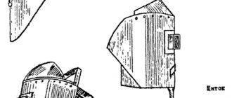
Heating from below
This technique is not only useful when working with a soldering gun, but also increases the convenience of soldering.
The board is secured with a clamp, the temperature is set to 200 degrees and warmed up for five minutes, after which they begin to work as usual.
Using thermal tape, you can shield nearby elements.
After removing the chip, the contacts are cleaned with the above braid. Do the same with the board.
All procedures must be carried out carefully to prevent damage to the circuit. If you don't have copper braid on hand, you can remove the solder using a soldering iron with a thin tip.
Required materials and tools
To solder SMD LEDs you will need:
- soldering iron with the necessary parameters;
- side cutters, tweezers, scissors;
- mounting needle or thin awl;
- solder and flux. Regular rosin or a special liquid composition, which is an alcohol solution, will do. An aspirin tablet is often used;
- thin brush for applying liquid flux;
- a magnifying glass on an adjustable stand (bracket), which is used by jewelers;
- soldering gun (component of a soldering station).
It will not be possible to do without flux, since molten solder without it does not wet the contacts and does not settle on the metal. Experts do not recommend an alcohol solution of rosin, as it is ineffective and leaves an indelible white residue.
Choosing a soldering iron is an important preparation step. The best option is a soldering station with a temperature control function. However, a regular low-voltage unit with a supply voltage of 12 to 36 V and a power of 20-30 W is also suitable. It is not recommended to work with a standard 220 V device, as their tip gets too hot. As a result, the flux evaporates faster than necessary, not fulfilling its task within the required limits. The maximum heating temperature is 260°.
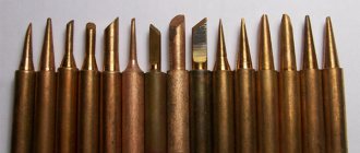
The type of sting tip is of great importance. A regular cone is not the best option; the optimal choice would be the so-called. microwave. This is a rod cut at approximately 45° with a small recess made in the axial direction. It is filled with liquid solder and allows you to more efficiently apply the material to the SMD LED pads and boards. If necessary, the microwave acts as a suction for excess solder, which avoids drips and drips.
The optimal type of solder is a thin wire with rosin inside. This type allows you to successfully solder LEDs with almost any soldering iron.
Features of working with BGA chips
When soldering BGA type microcircuits, the same temperature range is selected from 345 to 350 degrees, ensuring moderate air pressure to prevent blowing off the “neighbors”. During operation, the soldering gun should be held at an angle of 90 degrees with respect to the board. To avoid failure of the chip, you should not heat it only in the center; it is better to go around the mounting element around the perimeter.
After 1-3 minutes have elapsed, you can try to slightly lift the chip above the board using tweezers. If the chip does not budge, the solder is still hard. To avoid damage to the conductive paths of the board, you need to use the regulator on the hair dryer to “throw on top” 5 degrees of temperature and continue heating.
How to solder SMD components
Installation of LED elements is technologically significantly different from connecting a lamp. Soldering SMD LEDs requires some experience and skill. If there are none, it is recommended to first practice on some unnecessary pieces of wire. This will help you master the art of soldering and keep your LEDs in working order. Before starting work, you should inspect the surface of the board. If it is coated with varnish or a layer of silicone, the current-carrying paths to which the LEDs will be soldered should be freed from them.
The specificity of installing SMD LEDs is the absence of conventional long leads. The elements are installed on the board and soldered to the tracks, for which there are small areas on the sides of the LED device housings. The work requires accuracy and attention. It is important to remember the danger of heating, reducing the time the soldering iron touches SMD parts as much as possible. If there is no appropriate tool, a copper wire about 1 mm thick is wound around the tip of a regular soldering iron. One end of this winding serves as a sting, the heating temperature of which is significantly lower than that of the main element. Let's look at the procedure in more detail:
Work order
The soldering process consists of the following operations:
- removing a burnt-out LED (if necessary);
- cleaning conductive paths, applying flux to the soldering area;
- installing a new LED element in place;
- soldering of contacts;
- cleaning the soldering area from flux residues.
What you need for good soldering
- 1. Soldering iron EPSN 25 watt, with a tip sharpened into a needle, for mounting a new microcircuit.
- 2. Soldering iron EPSN 40-65 watts with a tip sharpened to a sharp cone, for dismantling a microcircuit, using Rose or Wood alloy. A soldering iron with a power of 40-65 watts must be turned on via a Dimmer, a device for regulating the power of the soldering iron. You can have one like the one in the photo below, very convenient.
- 3. Rose or Wood alloy. We bite off a piece of solder from the droplet with side cutters, and place it directly on the contacts of the microcircuit on both sides, if we have it, for example, in a Soic-8 package.
- 4. Dismantling braid. It is required to remove solder residues from the contacts on the board, as well as on the chip itself, after dismantling.
- 5. SKF flux (alcohol rosin flux, crushed into powder, dissolved in 97% alcohol, rosin), or RMA-223, or similar fluxes, preferably based on rosin.
- 6. Flux Off flux residue remover, or 646 solvent, and a small brush with medium-hard bristles, which is usually used in school, for painting in art lessons.
- 7. Tubular solder with flux, 0.5 mm in diameter (preferably, but not necessarily this diameter).
- 8. Tweezers, preferably curved, L-shaped.
Basic soldering principles and common mistakes
The process of soldering SMD LEDs consists of applying a thin layer of solder (a low-melting tin-lead alloy with various additives) simultaneously to the contacts of the attached part and the current-carrying tracks of the printed circuit board. Physical processes used:
- wetting of metals with melt;
- capillary impregnation of small gaps between contacts, ensuring connection both mechanically and electrically.
In order to solder SMD diodes, it is necessary to use a special soldering iron with low power and limit the time of contact of the LED device with the hot working part. Experts recommend not to exceed 3-5 seconds. A common mistake is to use soldering irons with a thin tip. This reduces the efficiency of heat transfer and does not allow high-quality heating of the contacts and traces of the printed circuit board.
Experienced people recommend using a normal tip, ground at an angle. The large mass will ensure rapid heating of the pads and melting of the solder, eliminating overheating of the LED. Liquid solder, under the influence of wetting and capillary absorption effects, flows into the smallest gaps between the element legs and the printed circuit board track, after which the hot soldering iron is removed to the side. The solder hardens and creates a monolithic area of strong connection of parts.
The second error leading to LED failure is overheating. Excessively long contact of the soldering iron with the legs of the LED element leads to an increase in the temperature of the emitting crystal. If you do not constantly control the duration of contact of the tip with the part, it will not be possible to avoid excessive heating.
Check in board
One of the most common ways to check a capacitor without removing it from the circuit is to connect in parallel another, previously working capacitor with a known rating.
This method allows you to judge the serviceability of the element by the device indicator, which shows the total capacity of two parallel-connected “condensers”. When capacitors are connected in parallel, their capacitances add up.
With this approach, it is possible to do without soldering the capacitor in order to remove it from the circuit in which it is shunted by elements (resistors) connected in parallel.
However, the possibilities of using this method are limited by the permissible voltages operating in a given electronic circuit and on the board of the device under test.
The method is effective only at small potentials comparable to the maximum voltage values for which the electrolytic capacitor is designed.
Soldering safety
- The tip of a hot soldering iron has a very high temperature, making it easy to set fire to something, melt plastic objects, or burn yourself.
- It is natural to hold a heated soldering iron only by the handle intended for this purpose.
- Do not disassemble the soldering iron - this may lead to electric shock, since during assembly, reliable insulation of the heating wires (220 V) from the metal of the case is not guaranteed.
- Solder fumes are toxic regardless of the filler metal used. Be careful not to inhale them. Make sure the room you are soldering in is well ventilated.
In addition, when soldering, it is recommended to protect your eyes, for example by wearing safety glasses - if you accidentally get on the liquid, hot solder can splash out to the sides. Remember what happens when you pour lead into water?
Capacity check
There are several ways to check electrolytic capacitors (as well as non-electrolytic ones) to ensure they maintain their nominal capacity (capacity).
But first you need to familiarize yourself with measuring instruments that allow you to correctly estimate the capacitance value of a particular element before soldering anything.
To measure capacitors with nominal capacities up to 20 microfarads, a conventional multimeter with the appropriate function may be sufficient. An inexpensive device like DT9802A can be used as such a meter.
To assess the condition of elements with high ratings, you will need a special device such as an “RLC meter”. Using such a device, you can test not only capacitors, but also such common elements as a resistor and inductor.
Checking the capacitor with a digital multimeter:
Often a faulty capacitor swells and is noticeable without the use of any instruments.
A simple, but not very effective method of identifying a malfunction is checking with a conventional ohmmeter, the reading of which can be used to judge the integrity of the dielectric gasket.
This method is usually used when the device does not have a capacitance measurement function. For these purposes, a simple pointer device can be used, switched to resistance measurement mode.
When the ends of the probe touch the legs of a working element, the arrow should deviate slightly and then return to a similar state.
If the readings on the device have changed, and the needle, after the deviation, has stopped at some final resistance value, this means that the capacitor is broken and must be replaced.
How to resolder a capacitor on the motherboard
Before soldering a new capacitor, you need to unsolder the old one. You should unsolder a damaged or faulty element from the motherboard as quickly as possible, so as not to overheat the contact pads, which otherwise may simply fall off.
To free the legs of the soldered element from solder, you should warm up the seat well. Only if it is sufficiently warmed up when soldering the capacitor is it possible to avoid damaging the board tracks.
When holding a small capacitor on one side, you need to try not to get burned, since its contact becomes hot when heated by a soldering iron.
In addition, you need to be as careful as possible and not use too much force, as the soldering iron tip can break off and damage adjacent parts.
The sequence of actions is as follows:
- First, turn off the power to the computer, disconnect not only the network cable, but also other power wires.
- Remove the cover and unscrew the motherboard.
- They inspect the board and find a damaged element, study its parameters (on the markings), and buy a replacement.
- Note what polarity the capacitor was connected to (you can take a photo).
- Using a soldering station or a soldering iron, the damaged capacitor is soldered out.
- Install and solder a new one.
After removing the capacitor, there remains a free space, which should first be carefully cleaned of solder residues using a suction.
Some radio amateurs use a sharpened match (toothpick) for this purpose, through which the mounting hole is pierced while simultaneously heating with the tip of the soldering iron tip.
Another way to free holes from solder residue involves drilling it out with a drill of a suitable size.
Upon completion of the preparation of the site for the new element, its legs should first be molded accordingly so that they easily fit into the mounting sockets. All that remains to be done after this is to solder it in place of the burnt one.