Odessa Radial Drilling Machine Plant (OZRSS) is a widely known machine-tool enterprise in the CIS countries and beyond, which produces a diverse range of metal-cutting equipment of the following types: radial drilling machines; vertical drilling machines; vertical grinding and lapping machines; horizontal deep drilling machines; tabletop horizontal milling machines; finishing and boring machines; drilling, milling and boring machines; box tables. The most popular models in the entire history of the plant are radial drilling machines 2A554, 2A554-1, 2A576, 2A587, 2A55, 2M55, 2M57, 2N55.
Information about the manufacturer of the screw-cutting lathe 16B05A
The manufacturer of the 16B05A screw-cutting lathe was the Odessa Machine Tool Plant .
Machine tools produced by the Odessa Machine Tool Plant (OSZ) and the Experimental Mechanical Plant (OMZ)
- 1P611
- high-precision screw-cutting lathe, Ø 250 - 16B05A
- especially high precision screw-cutting lathe, Ø 250 - 16B05P
- high-precision screw-cutting lathe, Ø 250, Kirovakan - 16M05A
- screw-cutting lathe of especially high precision, Ø 250 - 1601
— table lathe Ø 125 - 1604
— high-precision screw-cutting lathe, Ø 200 - 1613D
- precision screw-cutting lathe, Ø 240 x 270 - OT-4
- lightweight high-precision screw-cutting lathe, Ø 250 - OT-5
- high-precision, lightweight lathe-screw-cutting machine, Ø 250
Screw-cutting lathe
Lightweight screw-cutting lathe. Accuracy class – P (increased accuracy). Climatic modification U.4.1. Not built into an automatic line.
Purpose, scope
This type of equipment has shown good performance in small workshops, PARM. It is possible to cut all types of threads except pitch threads. Machining of parts in centers, collet, chuck or faceplate. Mainly used for repair work.
Technical indicators
Workpiece parameters:
- diameter above the bed – up to 250 mm;
- diameter above the caliper – up to 145 mm;
- rod diameter – 25 mm.
Spindle parameters:
- spindle speed varies from 30 to 3000 rpm;
- hole diameter – 26 mm.
16B05A screw-cutting lathe of particularly high precision. Purpose, scope
A particularly high-precision screw-cutting lathe 16B05A with a maximum processing diameter of 250 mm over the bed is designed to perform various high-precision turning operations performed in centers, collets, chucks and faceplates, as well as for cutting metric, inch and modular threads.
16B05A lathe provides high quality surface quality and work accuracy (accuracy of dimensions and geometric shapes).
16B05A machine is used at enterprises of the instrument-making, radio engineering, tool industries and precision engineering.
Operating principle and design features of the machine
16B05A lathe is hydrostatic spindle supports , which are activated by the machine’s hydrostatic unit.
The second feature is the fine feed drive in the machine feed box. During finishing, the feed box is driven by a belt drive from the variator to the feed box pulley. A lock in the control mechanism ensures that it is impossible to simultaneously turn on the feed from the belt drive and from the guitar.
Otherwise, the design of the 16B05A is identical to the design of the 16B05P
increased accuracy.
Installation of the variator on a special plate that does not have contact with the stand, as well as the independent suspension of the machine apron, reduces the level of vibration during processing and improves the quality of the machined surface.
The feed box provides the ability to cut a large number of metric, modular threads and obtain a wide range of longitudinal and transverse feeds without changing guitar gears. The spindle is mounted in original radial and thrust hydrostatic bearings, which, combined with the rigid design of the machine, allows for unique turning precision.
The machine is intended for use in climatic conditions UHL4.1 according to GOST 15150-69.
It is not built into an automatic line.
The accuracy class of the machine is A according to GOST 8-82E (especially high accuracy).
Developer: Odessa Design Bureau of Special Machine Tools.
Manufacturer: Odessa Machine Tool Plant.
Lathe designation
- 1
— lathe (group number according to ENIMS classification) - 6
– subgroup number (1, 2, 3, 4, 5, 6, 7, 8, 9) according to the ENIMS classification (6 - screw-cutting lathe) - B
– generation of the machine (A, B, C, D, K, L, M) - 0
– height of centers above the bed 135 mm - 5
- G
– machine with a recess in the bed - K
– machine with copying device - A
- machine accuracy - (n, p, v, a, s) according to GOST 8-82 (A - especially high accuracy) - F1
– machine with digital display device DRO and preset of coordinates - F2
– machine with CNC positional numerical control system - F3
– machine with contour (continuous) CNC system
Letters at the end of the model designation:
History of the OZRSS enterprise
The company was founded in 1884 as the Novorossiysk Mechanical and Iron Foundry. After the revolution of 1917 and the subsequent civil war, during which the plant was seriously destroyed, it was restored in 1924 under the name State Machine-Building Plant named after. V.I. Lenin.
Since July 1941, the enterprise was evacuated (Sterlitamak).
The restoration of the plant began in May 1944, on the site of the destroyed Remmashtrest workshops. In 1946, the enterprise was put into operation (under the name Odessa Machine Tool Plant) and produced its first products - radial machines.
In the 1960s, 1970s and 1980s, the plant was one of the leading industrial enterprises in Odessa.
In 1976, the plant became the parent enterprise of the Odessa Machine Tool Production Association.
As of the beginning of 1982, the plant was the only enterprise in the USSR that had the ability to produce radial drilling machines using the conveyor-line method. At this time, the plant produced radial drilling, diamond boring, honing, special and aggregate machines, as well as deep drilling machines (including high and high precision machines); a number of models of manufactured machines could operate in semi-automatic and automatic modes; some of the produced machines were equipped with numerical program control.
In Soviet times, the plant's balance sheet included social infrastructure facilities in Odessa (the Luzanovka recreation center, the Radialka stadium and departmental housing stock); by the end of the 1980s, the number of employees of the enterprise was 5.5 thousand people.
After the declaration of independence of Ukraine in June 1994, the plant was transformed into an open joint-stock company.
In the 1990s, the situation of the enterprise became more complicated (in the conditions of non-payments and inflation in the early 1990s, the plant for some time had to work with clients using barter schemes for the exchange of goods).
In May 1995, the Cabinet of Ministers of Ukraine included the Odessa Radial Drilling Machines Plant in the list of enterprises subject to privatization during 1995.
In August 1997, OZRSS was included in the list of enterprises of strategic importance for the economy and security of Ukraine.
In April 1999, the Cabinet of Ministers of Ukraine decided to sell 15% of the company's shares (until that time state-owned); in December 2005, a decision was made to sell the remaining 15.02% of the company's shares in state ownership.
In the spring of 2000, a plan was proposed for the rehabilitation of Odessa machine tool manufacturing facilities (by this time 40% of Ukraine’s machine tool manufacturing capacity was concentrated in the city - 9 factories, one research institute and four design bureaus), according to which it was proposed to first restore the three largest enterprises: Odessa plant of precision machine tools "Mikron", Odessa plant of radial drilling machines and "Pressmash".
In the first half of the 2000s, the plant (which retained the foundry) carried out metal casting work.
In 2007, the factory boiler room failed and was decommissioned.
The economic crisis that began in 2008 complicated the situation of the plant; from the beginning of 2009, workers were no longer paid wages, and subsequently the plant practically ceased production activities.
As of the beginning of 2013, the plant was one of the operating industrial enterprises in Odessa.
In April 2013, following a claim by the commercial bank Prominvestbank, the accounts of the OZRSS enterprise were seized; in May 2013, by decision of the economic court of Odessa, two factory workshops were sold to repay the debt to the bank on a previously received loan (mechanical shop No. 3 with an area of 1. 6 thousand m² and a building with an area of 2.2 thousand m²).
On March 30, 2014, the premises of the factory warehouse were damaged as a result of a fire.
By the beginning of June 2015, the situation of the enterprise was unfavorable, the number of plant employees was about 100 people, part of the production space was leased.
Official website of the Odessa Radial Drilling Machines Plant (OZRSS) - www.ozrsv.com (https://www.ozrsv.com)
The Stanochny Mir company offers to buy machines from the Odessa Radial Drilling Machines Plant or analogues at an affordable price.
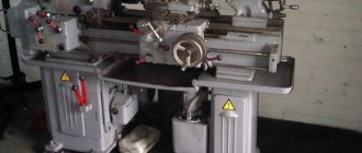
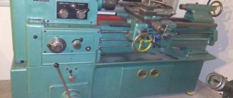
16B05A General view of a screw-cutting lathe
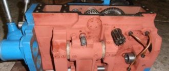
Photo of screw-cutting lathe 16B05a
Photo of screw-cutting lathe 16B05a
Photo of screw-cutting lathe 16B05a
Photo of screw-cutting lathe 16B05a
Information about the manufacturer of the screw-cutting lathe 16М05А
The manufacturer of the 16M05A screw-cutting lathe was the Odessa Machine Tool Plant .
Machine tools produced by the Odessa Machine Tool Plant (OSZ) and the Experimental Mechanical Plant (OMZ)
- 1P611
- high-precision screw-cutting lathe, Ø 250 - 16B05A
- especially high precision screw-cutting lathe, Ø 250 - 16B05P
- high-precision screw-cutting lathe, Ø 250, Kirovakan - 16M05A
- screw-cutting lathe of especially high precision, Ø 250 - 1601
— table lathe Ø 125 - 1604
— high-precision screw-cutting lathe, Ø 200 - 1613D
- precision screw-cutting lathe, Ø 240 x 270 - OT-4
- lightweight high-precision screw-cutting lathe, Ø 250 - OT-5
- high-precision, lightweight lathe-screw-cutting machine, Ø 250
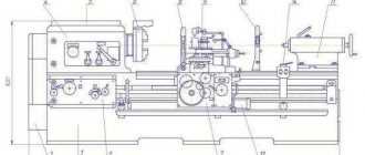
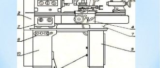
16B05A Arrangement of components of a screw-cutting lathe
Location of the main components of the screw-cutting lathe 16B05a
List of components of screw-cutting lathe 16B05A
- Bed - 16B05A.111.000
- Cabinet - 16B05A.121.000
- CVT - 16B05A.212.000
- Front headstock - 16B05A.221.000
- Guitar - 16B05A.311.000
- Feed box - 16B05A.321.000
- Apron - 16B05A.331.000
- Caliper - 16B05A.343.000
- Cooling - 16B04A.511.000
- Fencing - 16B04A.611.000
- Shield - 16B05A.621.000
- Hydrostatic unit - 16B04A.071.000
- Coolant pump unit - 16B04A.714.000
- Hydrocommunications - 16B04A.721.000
- Rear headstock - 16B05A.231.000
- Electrical equipment - 16B04A.811.000
- Switch - 16B05A.822.000
- Control and monitoring unit - 16B04A.715.000
16B05A Location of controls for a screw-cutting lathe
Location of controls for screw-cutting lathe 16B05a
List of controls for screw-cutting lathe 16B05A
- 1. “Stop” button and spindle braking
- 2. Speed selector knob
- 3. “Start” button for direct spindle rotation
- 4. “Start” button for spindle reverse rotation
- 6. Thread pitch increasing link handle
- 7. Feed drive reverse handle
- 9. Handle for switching feeds and threads
- 10. Feed and thread switching handle
- 11. Handle for turning on the lead screw or lead shaft
- 12. Handle for switching feeds and threads
- 13. Handle for switching feeds and threads
- 14. CVT gear shift knob
- 16. Handwheel for changing spindle speeds
- 18. Handle for turning on the apron safety device
- 19. Handwheel for adjusting the amount of traction force
- 21. Handle for turning on the uterine nut
- 22. Button for switching longitudinal and transverse feed of the caliper
- 24. Handwheel for moving the tailstock quill
- 25. Tailstock clamp handle
- 26. Handle for moving the upper carriage
- 27. Tailstock quill clamp handle
- 29. Light switch
- 30. Tool holder clamp handle
- 31. Manual lateral movement handle
- 32. Handwheel for manual longitudinal movement
- 33. Button for turning on the handwheel and longitudinal feed dial
- 35. Cooling switch
- 38. Introductory machine
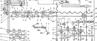
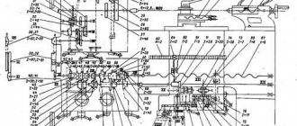
16B05A Kinematic diagram of a screw-cutting lathe and bearing arrangement
Kinematic diagram of a screw-cutting lathe 16B05a
The kinematic diagram of the machine allows the following operations:
- the main movement is spindle rotation
- feed movement - cutter movement
- rotation of the lubrication pump
Operating instructions, passport
Before starting work, it is necessary to check the oil level in the oil indicators. Apply the required amount of oil to all indicated lubrication points. Check the strainers for chips and dirt. If necessary, rinse in kerosene.
Pour coolant into a special container in the cabinet.
Conduct an external inspection of electrical equipment.
- Why get started:
- Set the spindle rotation speed.
- Set the feed amount.
- Start work.
After finishing, clean the machine from chips and dirt, clean the filters.
The lathe's passport can be downloaded for free from the link - Passport for the OT-5 screw-cutting lathe.
16B05A Variator for screw-cutting lathe
Variator of screw-cutting lathe 16B05a
CVT (continuously variable gearbox)
The variator consists of the variator itself and a two-stage gearbox (range shift box).
The first (drive) shaft 2 of the variator is driven into rotation by a flanged electric motor through a gear coupling half. The second half of the coupling is made integral with shaft 2, on which a stationary (in the axial direction) disk 4 and a spring-loaded sliding disk 3 are installed, forming the variator drive pulley. From this pulley, rotation is transmitted through a wide V-belt to shaft 7 through the driven variator pulley, consisting of a fixed disk 5 and a controlled sliding disk 6.
In addition to the driven pulley, gears 8 and 9 are located on shaft 7. Gear 9 is equipped with an outer and inner ring gear and a half-coupling. Gear 8, moving along the splines along shaft 7, switches the speed ranges of the variator output shaft. The drive pulley of the V-belt drive, connecting the variator to the headstock, is mounted on this shaft. To tension the transmission, the housing 11 of the variator gearbox can be rotated on the glass 10, mounted on the housing 1 of the variator. The housing 11 is rotated using the coupling nut 21, after which the housing is secured with screws to the glass 10.
The control mechanism for the variator and gearbox is located on top of the variator body. Handwheel 12 controls the movement of sliding disk 6, handle 16 serves to switch gears in the gearbox. A planetary gear 20—19—18—17 connects the handwheel 12 with a disk 13, on which a ring 14 with a dial 15 is installed. There are two spindle speed scales on the dial, one for directly turning on the spindle, the second for turning on the spindle through overdrive.
To read the scales, two pairs of indicator strokes are used, printed on a transparent shield located above the dial. When switching variator speeds, the shield moves together with handle 16. For counting, use the pair of index strokes that is currently in the upper position.
16B05A Spindle head of screw-cutting lathe
Spindle head of screw-cutting lathe 16B05a
The headstock housing contains:
- spindle
- overkill
- drive of threads and feeds with bit
- control mechanism
The gear ratio of the headstock is 1/8. The control of the headstock 6, 7 and the direct clutch 10 is carried out with one handle. Next to the selection gear 11 on the spindle 4 there is a gear 3 for driving threads and feeds. The gear wheel 1, located on the first shaft 12 of the drive of threads and feeds, can be connected either to the gear wheel 11, or to the gear wheel 3 sitting on the spindle. This makes it possible to increase the thread pitch when enumeration is turned on.
Changing the direction of feed or cut thread is carried out by a snaffle consisting of a double gear wheel 13, a sliding gear wheel 15 and a parasitic wheel 16. The wheel 15 is seated on the splines of the output shaft 14, onto the end of which one of the replacement wheels of the guitar is put on.
The control handles for the headstock mechanisms are located on the front wall of the headstock. A cast casing is attached to the headstock body 5 in front, in which control buttons for the main electric motor are installed.
Lubrication of the headstock mechanisms is centralized, from a lubrication unit.
16B05A Feed box for screw-cutting lathe
Feed box for screw-cutting lathe 16B05a
The feed box of the machine (Fig. 6.6) in combination with the guitar allows you to set the required gear ratios for cutting threads with different pitches and obtaining different longitudinal and transverse feeds.
The feed box contains the following mechanisms:
- Main row mechanism (gears 1, 2, 3, 4, 18, 21, 22, 23)
- Multiplying mechanism (gears 5, 6, 14, 15, 16, 17, 26)
- Row shift mechanism (gears 19, 20, 22, 23)
- Mechanism for switching the transmission of motion to the lead shaft or to the lead screw (half-coupling 13, gears 11, 10, 9, 7)
- Mechanism for direct engagement of the lead screw (coupling halves 13, 17)
- Belt drive mechanism for fine feeds from a variator (pulley 24)
- Switching mechanism (not shown in figure)
The main series mechanism makes it possible to obtain four gear ratios proportional to the four pitches of metric or modular threads.
By multiplying these ratios by the multiplying gear ratios (1/4, 1/2, 1, 2) and by the row shifting gear ratios (1.1 1/4), metric and modular threads can be cut while constantly tuning the guitar.
The switching mechanisms are located on the plate under the feed box cover. The shift handles are located on the front cover.
Oil pressure from the unit is supplied to the front and rear support bearings and is regulated by two hydraulic pressure valves.
The hydrostatic unit also provides centralized lubrication of gears and bearings of the spindle head, feed box and variator.
16М05А Kinematic diagram of a screw-cutting lathe
Kinematic diagram of a screw-cutting lathe 16m05a
The kinematic diagram of the machine allows the following operations:
- spindle rotation - main movement drive
- movement of the cutter - drive of threads and normal feeds, drive of fine feeds
- rotation of the lubrication pump
Main drive
Electric motor 1, using clutch 2, rotates shaft 1 with the drive pulley of the variator 3. Rotation from the drive pulley to the driven pulley 4 is transmitted by a wide V-belt. The change in the rotation speed of driven shaft II is ensured by changing the working diameters of the variator pulleys when moving the controlled part of the driven pulley and the corresponding movement of the spring-loaded part of the drive pulley.
Rotation is transmitted to shaft III and pulley 9 using a toothed block 5, 7 and gears 6, 8. Pulley 9 is connected to pulley 17 by V-belts. Rotation from sleeve V is transmitted to spindle VII either directly when clutch 22 is engaged, or through a gear consisting of a gear 18 connected to sleeve V, gears 19, 20 mounted on shaft VI, and a gear 21 mounted on the spindle.
Drive of threads and normal feeds
When cutting threads, rotation from spindle VII is transmitted to shaft VIII using gears 23, 24 or, when the search is turned on (gears 18, 19, 20, 21), using gears 18,24.
Shaft IX receives rotation in the forward direction using gears 25, 27, in the opposite direction using gears 25, 26, 27. Replaceable guitar gears a, b, c, d transmit rotation to shaft XI of the feed box. The feed box contains the following mechanisms:
- mechanism for shifting a number of gears 30, 31, 32, 33
- main row mechanism - gears 33, 34, 31, 35, 36, 37, 38, 39
- multiplying mechanism - gears 40, 42, 43,45, 51, 44, 46
After these mechanisms, rotation is transmitted either to the lead screw 81 for cutting threads when the jaw clutch on the gear wheel 47 and on the XVI shaft is disconnected, or to the lead shaft XIX using gears 47, 48, 49, 51.
From the running roller, rotation is transmitted via clutch 54 to the worm 55 of the machine apron. Next, rotation is transmitted to shaft XXI using a worm wheel 56, a planetary gearbox consisting of gears 57, 58, 59, 60 and gears 61, 62. From shaft XXI, rotation is transmitted either to the rack and pinion gear 65 using gears 63,64 (longitudinal movement of the cutter), or to the screw 83 using gears 62, 70 (transverse movement of the cutter)
Fine feed drive
The rotation of the feedbox mechanism is transmitted from shaft III of the variator using gears 10, 11, V-belt transmission, pulleys 12, 28, to the XXV feedbox shaft and then gear 28 transmits rotation to gear 33 of the mechanism for changing the pitch of the feedbox.
Changing the direction of longitudinal or transverse feed is ensured by transmitting rotation to the running shaft XIX from the feed box shaft XV through a snaffle consisting of gears 49, 50, 51 when gear 49 is switched.
Planetary mechanism
Gears 13, 14, 15, 16 form a planetary mechanism, which provides rotation of the spindle speed reading scale when reconfiguring the variator rotation speed.
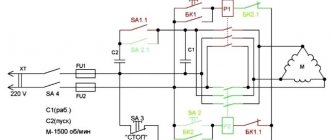
Hydraulic system of machine 16B05a
The hydraulic system in the machine carries out:
- power supply for hydrostatic spindle supports;
- lubrication of gears of the headstock and gearbox;
- lubrication of variator gears;
- lubrication of gearbox gears.
16B05A machine consists of the following components and groups:
- hydrostatic unit;
- hydrocommunications;
- spindle load control unit.
The “Hydrostatic unit” group includes the following units:
- control and monitoring unit;
- pumping installation.
The “Hydrostatic unit” group is a complete installation, including a pumping unit, filtration, regulation and pressure control equipment.
Capabilities of screw-cutting lathes
Steel ball, completely manufactured on a 16B05a lathe
The photograph shows a steel ball that has been completely machined on a lathe.
From a solid workpiece, using a set of tools, it is possible to turn a ball in a ball , a cube in a cube in a cube and in a cube , a cube in a dodecahedron , which in turn is in a ball, a ring in a ring .
Main technical characteristics of the machine 16B05A
| Parameter name | 16M05A | 16B05A |
| Basic machine parameters | ||
| Accuracy class | A | A |
| The largest diameter of the workpiece processed above the bed, mm | 250 | 250 |
| The largest diameter of the workpiece installed above the bed, mm | 270 | |
| The largest diameter of the workpiece installed above the caliper, mm | 139 | 145 |
| Maximum length of the workpiece at centers (RMC), mm | 500 | 500 |
| Height of centers above flat bed guides, mm | 135 | 135 |
| The greatest distance from the axis of the centers to the edge of the tool holder, mm | 135 | 135 |
| Diameter of the workpiece installed in the chuck, mm | 5..160 | |
| Diameter of the workpiece installed in the collet, mm | 4..28 | |
| Diameter of the workpiece installed in the steady rest, mm | 5..50 | |
| Sample processing accuracy indicators: roundness, microns | 1,2 | |
| Roughness indicators for processing non-ferrous metal samples, microns | 0,04 | |
| Roughness indicators for processing steel samples, microns | 0,63 | |
| Productivity increase factor compared to the machine model 16B05A | 1,2 | |
| Spindle | ||
| Spindle hole diameter, mm | 32 | 26,5 |
| The largest diameter of the rod passing through the hole in the spindle, mm | 26 | |
| Spindle center according to GOST 13214-67 | Morse 4 | Morse 4 |
| Spindle end according to GOST 12593-72 | 4K | 4K |
| Number of speed steps for direct spindle rotation | b/s regulation | b/s regulation |
| Spindle direct rotation frequency, rpm | 25..2500 | 25..2500 |
| Spindle braking | There is | There is |
| Handle lock | ||
| Caliper. Submissions | ||
| Maximum longitudinal movement of the caliper, mm | 520 | 520 |
| Maximum lateral movement of the caliper, mm | 160 | 160 |
| Transverse movement of the caliper by one division of the dial, mm | 0,02 | 0,02 |
| Number of longitudinal feeds of the caliper | 28 | 28 |
| Number of cross feeds | 28 | 28 |
| Limits of longitudinal caliper feeds (in brackets - when using a pitch increasing link), mm/rev | 0,01..0,35 (0,01..2,8) | 0,01..0,35 (0,01..2,8) |
| Transverse caliper feed limits (in parentheses - when using a pitch increasing link), mm/rev | 0,005..0,175 (0,005..1,4) | 0,005..0,175 (0,005..1,4) |
| Steps of cut metric threads, mm | 0,2..28 | 0,2..28 |
| Steps of cut modular threads, mod | 0,1..14 | 0,1..14 |
| Steps of cut inch threads, threads per inch | 5..96 | 5..96 |
| Speed of rapid movements, mm/min | No | No |
| Cutting slide | ||
| Maximum length of movement of the cutting slide, mm | 150 | 150 |
| Movement of the cutting slide by one division of the dial, mm | 0,02 | 0,02 |
| Maximum angle of rotation of the cutting slide, degrees | ±45° | ±45° |
| Scale division of the tool slide rotation scale, deg | 1° | 1° |
| The largest cross-section of the cutter holder, mm | 16 x 16 | 16 x 16 |
| Height from the supporting surface of the cutter to the axis of the centers (cutter height), mm | 16 | 16 |
| Number of cutters in the cutting head | 4 | 4 |
| Tailstock | ||
| Quill diameter, mm | ||
| Tailstock quill hole cone according to GOST 2847-67 | Morse 3 | Morse 3 |
| Maximum movement of the quill, mm | 85 | 85 |
| Movement of the quill by one division of the dial, mm | 0,02 | 0,02 |
| Moving the quill by one ruler, mm | 1 | 1 |
| The amount of lateral displacement of the headstock body, mm | ±10 | ±10 |
| Electrical equipment | ||
| Number of electric motors installed on the machine | 3 | 3 |
| Main drive electric motor, kW | 1,5 | 1,5 |
| Hydraulic pump electric motor, kW | 2,2 | 0,75 |
| Coolant pump electric motor, kW | 0,12 | 0,12 |
| Total power of electric motors installed on the machine, kW | 3,82 | 2,37 |
| Dimensions and weight of the machine | ||
| Machine dimensions (length width height), mm | 1550 x 1350 x 1400 | 1530 x 910 x 1385 |
| Machine weight, kg | 1400 | 1365 |
- Extra high precision screw-cutting lathe 16B05A. Operating manual, Odessa, 1984
- High-precision screw-cutting lathes 16B04P, 16B05A. Operating manual, Odessa, 1976
- Acherkan N.S. Metal-cutting machines, Volume 1, 1965
- Denezhny P.M., Stiskin G.M., Thor I.E. Turning, 1972. (1k62)
- Denezhny P.M., Stiskin G.M., Thor I.E. Turning, 1979. (16k20)
- Batov V.P. Lathes., 1978
- Modzelevsky A. A., Muschinkin A. A., Kedrov S. S., Sobol A. M., Zavgorodniy Yu. P., Lathes, 1973
- Tepinkichiev V.K. Metal cutting machines, 1973
- Skhirtladze A.G., Novikov V.Yu. Technological equipment for machine-building industries, 1980
- Chernov N.N. Metal cutting machines, 1988
Bibliography:
Related Links. Additional Information
- Classification and main characteristics of turning
- Selecting the right metalworking machine
- Multi-start thread. Methods for cutting multi-start threads on a lathe
- Graphic signs for lathes
- Friction clutch of a screw-cutting lathe
- Methodology for checking and testing screw-cutting lathes for accuracy
- Directory of lathe manufacturing plants
- Directory of lathes
Home About the company News Articles Price list Contacts Reference information Interesting video KPO woodworking machines Manufacturers
Main technical characteristics of the machine 16М05А
| Parameter name | 16M05A | 16B05A |
| Basic machine parameters | ||
| Accuracy class | A | A |
| The largest diameter of the workpiece processed above the bed, mm | 250 | 250 |
| The largest diameter of the workpiece installed above the bed, mm | 270 | |
| The largest diameter of the workpiece installed above the caliper, mm | 139 | 145 |
| Maximum length of the workpiece at centers (RMC), mm | 500 | 500 |
| Height of centers above flat bed guides, mm | 135 | 135 |
| The greatest distance from the axis of the centers to the edge of the tool holder, mm | 135 | 135 |
| Diameter of the workpiece installed in the chuck, mm | 5..160 | |
| Diameter of the workpiece installed in the collet, mm | 4..28 | |
| Diameter of the workpiece installed in the steady rest, mm | 5..50 | |
| Sample processing accuracy indicators: roundness, microns | 1,2 | |
| Roughness indicators for processing non-ferrous metal samples, microns | 0,04 | |
| Roughness indicators for processing steel samples, microns | 0,63 | |
| Productivity increase factor compared to the machine model 16B05A | 1,2 | |
| Spindle | ||
| Spindle hole diameter, mm | 32 | 26,5 |
| The largest diameter of the rod passing through the hole in the spindle, mm | 26 | |
| Spindle center according to GOST 13214-67 | Morse 5 | Morse 4 |
| Spindle end according to GOST 12593-72 | 4K | 4K |
| Number of speed steps for direct spindle rotation | b/s regulation | b/s regulation |
| Spindle direct rotation frequency, rpm | 25..2500 | 25..2500 |
| Spindle braking | There is | There is |
| Handle lock | ||
| Caliper. Submissions | ||
| Maximum longitudinal movement of the caliper, mm | 520 | 520 |
| Maximum lateral movement of the caliper, mm | 160 | 160 |
| Transverse movement of the caliper by one division of the dial, mm | 0,02 | 0,02 |
| Number of longitudinal feeds of the caliper | 28 | 28 |
| Number of cross feeds | 28 | 28 |
| Limits of longitudinal caliper feeds (in brackets - when using a pitch increasing link), mm/rev | 0,01..0,35 (0,01..2,8) | 0,01..0,35 (0,01..2,8) |
| Transverse caliper feed limits (in parentheses - when using a pitch increasing link), mm/rev | 0,005..0,175 (0,005..1,4) | 0,005..0,175 (0,005..1,4) |
| Steps of cut metric threads, mm | 0,2..28 | 0,2..28 |
| Steps of cut modular threads, mod | 0,1..14 | 0,1..14 |
| Steps of cut inch threads, threads per inch | 5..96 | 5..96 |
| Speed of rapid movements, mm/min | No | No |
| Cutting slide | ||
| Maximum length of movement of the cutting slide, mm | 150 | 150 |
| Movement of the cutting slide by one division of the dial, mm | 0,02 | 0,02 |
| Maximum angle of rotation of the cutting slide, degrees | ±45° | ±45° |
| Scale division of the tool slide rotation scale, deg | 1° | 1° |
| The largest cross-section of the cutter holder, mm | 16 x 16 | 16 x 16 |
| Height from the supporting surface of the cutter to the axis of the centers (cutter height), mm | 16 | 16 |
| Number of cutters in the cutting head | 4 | 4 |
| Tailstock | ||
| Quill diameter, mm | ||
| Tailstock quill hole cone according to GOST 2847-67 | Morse 3 | Morse 3 |
| Maximum movement of the quill, mm | 85 | 85 |
| Movement of the quill by one division of the dial, mm | 0,02 | 0,02 |
| Moving the quill by one ruler, mm | 1 | 1 |
| The amount of lateral displacement of the headstock body, mm | ±10 | ±10 |
| Electrical equipment | ||
| Number of electric motors installed on the machine | 3 | 3 |
| Main drive electric motor, kW | 1,5 | 1,5 |
| Hydraulic pump electric motor, kW | 2,2 | 0,75 |
| Coolant pump electric motor, kW | 0,12 | 0,12 |
| Total power of electric motors installed on the machine, kW | 3,82 | 2,37 |
| Dimensions and weight of the machine | ||
| Machine dimensions (length width height), mm | 1550 x 1350 x 1400 | 1530 x 910 x 1385 |
| Machine weight, kg | 1400 | 1365 |
- Extra high precision screw-cutting lathe 16M05A. Operating manual 16М05А.000.000 RE, 1989
- Acherkan N.S. Metal-cutting machines, Volume 1, 1965
- Batov V.P. Lathes, 1978
- Beletsky D.G. Handbook of a universal turner, 1987
- Denezhny P.M., Stiskin G.M., Thor I.E. Turning, 1972. (1k62)
- Denezhny P.M., Stiskin G.M., Thor I.E. Turning, 1979. (16k20)
- Modzelevsky A. A., Muschinkin A. A., Kedrov S. S., Sobol A. M., Zavgorodniy Yu. P., Lathes, 1973
- Pikus M.Yu. A mechanic's guide to machine repair, 1987
- Skhirtladze A.G., Novikov V.Yu. Technological equipment for machine-building industries, 1980
- Tepinkichiev V.K. Metal cutting machines, 1973
- Chernov N.N. Metal cutting machines, 1988
Bibliography:
Related Links. Additional Information
- Classification and main characteristics of turning
- Selecting the right metalworking machine
- Multi-start thread. Methods for cutting multi-start threads on a lathe
- Graphic signs for lathes
- Friction clutch of a screw-cutting lathe
- Methodology for checking and testing screw-cutting lathes for accuracy
- Directory of lathe manufacturing plants
- Directory of lathes
Home About the company News Articles Price list Contacts Reference information Interesting video KPO woodworking machines Manufacturers