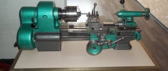
The profession of “turner” was popularized in the late 70s and until the 90s. And the TV-6 lathe and its predecessor TV-4 helped make it popular. Now the new generation unit has completely taken over the function of a training lathe. This device is used to train students who will subsequently become specialists in their field. This device has a rather modest limit of work performed, however, this is enough to perform simple tasks.
The 6 6 lathe can be considered one of the lightest, which allows it to be installed in large quantities in one room prepared for turning work (in educational institutions, workshops, etc.).
Dimensions of equipment and workspace
The TV-6 lathe is characterized by the following value:
- 5 m long;
- 5 m wide;
- 4 m high;
- its weight is up to 300 kg.
Such dimensions turn out to be extremely small for this kind of units, because in order for turning to be carried out, a set of mechanisms is required (including the engine), which take up a lot of space. The workspace is located in the center of the machine tabletop and has dimensions in mm:
- 1100 in length;
- 470 width;
- 110 height.
This is the space that is required to perform any operation on the equipment. Above this working area there is a transparent protective casing that prevents chips from accidentally getting into the eyes, as well as foreign objects from entering the working area, while you can observe the progress of the work process.
Differences between TV-4 and TV-4
There are no fundamental differences in the design of the two machines. Some changes are listed below:
- The drive power has been slightly increased (from 1 to 1.1 kW).
- Due to the fact that the gear module in the KS has been increased (1.5 instead of 1.25 for the TV-4), the speeds have changed slightly, although, in fact, they remained in the same range.
- The machine became 34 cm shorter, but 8 cm taller. Apparently, the designers took into account teenage acceleration in the 70s of the last century.
- The diameter of the through hole in the spindle was reduced by 3 mm in order to increase its rigidity.
- The conical hole in the spindle has been enlarged to accommodate a fixed center (Morse No. 3).
- The machine has acquired a standard protective fence for the working area.
- The stroke of the upper slide has been increased: 85 mm instead of 50.
- The weight of the machine increased by 20 kg: 300 versus 280 for the TV-4.
What is possible for TV-6
This turning tool is capable of performing the following types of tasks:
- trimming blanks;
- drilling washers and rods;
- cutting parts;
- spline selection;
- thread cutting;
- chamfering.
All work is done with cylindrical and conical workpieces. In the Improved version, work can be carried out on milling parts.
Such operations are performed with limitations in the capabilities of the equipment. Here are the technical characteristics that make it possible to operate the TV-6 lathe:
- the longest workpiece length is 350 mm, while the processed part is 300 mm, and 50 are in fastening;
- diameter of the workpiece maximum 200 mm;
- The maximum turning speed is 170 rpm.
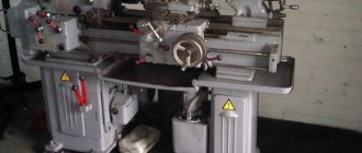
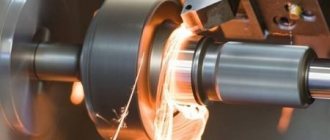
Metal lathe TV-6
Using the device
Although this turning equipment, according to the description, is considered educational, with its help it is possible to achieve excellent accuracy and carry out rather complex turning procedures. Because of this, these machines are often purchased by home workshop owners.
The device is driven by V-belt drives. It is necessary to ensure that the belts are constantly tensioned. This will make it possible to make maximum use of the drive power and significantly increase the operational period of the transmission. If the belts are loose, they can be adjusted. To do this, you need to slightly unscrew the nuts that connect the slide to the motor, set the desired tension (ten kilograms per 1 branch of the wedge belt).
Quite often a problem occurs in TV-6, which consists in vibration of the spindle element. It may appear because the connecting screws have become loose. If you tighten the spindle nuts and the vibration continues, the bearings are broken.
If there are gaps in the bearings, you can get rid of them by grinding the end parts of the compensation rings or adjusting the nuts. These methods can only eliminate small gaps of the radial/axial type.
TV-6, like any other machine, needs to be regularly maintained and repaired. Only in this case will it work for a long time and make it possible to process workpieces with high precision.
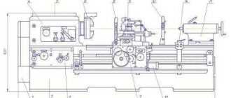
What does the unit consist of?
Turning a part or turning out a new one is a rather complex job that requires high precision. Therefore, to carry out this kind of function it is necessary to use complex mechanisms that are driven mechanically and electrically. The entire unit consists of several complex mechanical and electrical structures. Just like for the 4-TV unit, there is a set of elements for the TV-6 turning mechanism.
Here is a description of all the elements present in the TV-6 lathe:
- headstock;
- tailstock;
- bed;
- gearbox;
- caliper;
- bed guides;
- engine;
- caliper apron;
- pallet.
TS-TV6 details
Headstock functions
The headstock of the TV 6 screw-cutting lathe serves to hold the part, as well as to transmit rotational movements to the workpiece. The part is held by securing it in the headstock head. Also, the headstock, which is located on the left side of the frame, contains gears that transmit rotational movements. These gears are necessary for changing speed modes of rotation. Speed change is made by one of 3 switches located on the front of the headstock.
Purpose of the tailstock
It works in tandem with the front one, and it is located on the opposite side, that is, on the right side of the frame. The functional purpose of the tailstock is the same as the front one - holding and rotating the workpiece being processed. However, the tailstock tends to move on runners and does not contain a complex mechanism of gears.
The main task of the tailstock is to hold the part in the desired position, namely vertically. In the absence of this element, precession of the part during rotation is inevitable. But to perform work such as drilling holes, the tailstock is needed to feed the product onto the drill.
How the bed works
As with other units, the bed for the 6 6 lathe serves as a supporting structure. The necessary elements of the mechanism are concentrated on the frame. At the same time, the characteristics of this design must meet the necessary requirements. In this case, the frame has compact dimensions and can withstand up to 600 kg of weight, with the weight of the device itself being 300 kg.
Purpose of the feed box
The function of the feed box is to switch the speeds of the shaft and screw. To do this, there are two levers on the feed box panel that drive one of the elements - the shaft or the screw. Also, all gears are lubricated through the feed box.
Cabinet
The design of the lathe divides the cabinet into two parts: front and back. They have a similar, but different structure.
The front cabinet is assembled in the shape of the letter “P”. To make the structure more durable, stiffening ribs are mounted at the bottom and top. The engine is located at the back of the cabinet. It turns on (off) by pressing a button located on the front of the cabinet.
The difference between the rear cabinet is that its design includes an electrical panel instead of a motor.
Why is a caliper apron needed?
One of the main elements of the machine is the support apron. Its task is to feed the cutter. The apron itself consists of an element lying on skids, the movement of which is carried out along a perpendicular line with the workpiece. Also, on the apron there is a caliper and control levers for the movement of the caliper and apron. In operation it looks like this:
- the cutter is fed onto the part by levers located on the apron;
- the caliper apron itself moves left or right, removing a layer of metal from the rotating part.
Caliper functions
For the TV 6 screw-cutting lathe, the support serves as a holder for cutters, as well as their feed towards the center of the diameter of the workpiece or part. The support located on the apron feeds the cutter throughout the entire working process.
It is worth noting that a malfunction of this element can lead to inaccurate turning, which is extremely undesirable in turning. In order for the caliper to serve for a long time, all the bolts on it must be tightened as much as possible, this reduces vibration and increases service life.
How to buy a used machine
- Warning: when buying from an ad in another region, you may end up with unscrupulous sellers. Or the product may not meet the declared condition, or they will offer a higher price. As a result, money for the trip will be thrown away. So it's better to look for an offer closer.
What to pay attention to when purchasing:
- Availability of chuck, jaws, tailstock, electric motor. Moreover, if the electric motor can still be purchased, then the tailstock is quite difficult to get (they are often sold for scrap metal, since they can be removed from the machine quite easily).
- It is necessary to make sure that the machine spindle rotates and the slide movement is activated. If the electric motor does not work, you can rotate the spindle manually using the drive pulley. If something doesn't rotate or move, there is obviously something wrong.
- Check how worn the rubbing surfaces are, as well as the radial chatter of the spindle and tailstock quill. Any fault found is a reason to reduce the price. If there are many faults, it is better to refuse the purchase even for a small amount. Because repairs can cost a pretty penny.
That's all that can be said in one article. Additional information can be found on thematic forums. It turns out that there are many people who enjoy learning the craft of turning and share their practical experience. Unfortunately, statements are sometimes controversial. In doubtful cases, it is better to seek advice from an experienced professional turner.
What are the bed guides, pallet and motor needed for?
The caliper apron and tailstock move along these guides or runners. The skids have the character of powerful and smooth rails, the evenness of which plays a role in the quality of the work performed. It is worth noting that on this version of the turning unit, the bed guides had no cases of malfunction. Their quality is designed to last for many years of service.
The pallet has the shape of a tabletop located on the bed, under all elements of the machine. It serves to collect lubricant (oil) flowing from lubricated mechanisms during operation.
The electric motor is located under the pallet, at the bottom of the frame. It drives the entire mechanism thanks to a belt drive.
For accurate operation of the machine, it is necessary to monitor the serviceability of each element, promptly lubricate the component parts with oil, and keep the unit clean. For safe operation, you must adhere to the rules for using electrical equipment.
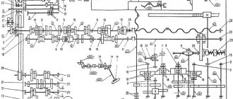
Control diagram
The control diagram has:
- A handle that sets the rotation speed of the spindle assembly.
- Another handle that sets the rotation speed of the spindle assembly.
- A handle that sets thread cutting (right and left) and changes the direction of feed.
- A handle that sets the feed rate and thread pitch.
- A handle that switches the roller.
- Reversing button that turns the machine on and off.
- Lever protecting the cartridge.
- Availability of a protective screen.
- Handle securing the cutting head.
- Light source for illuminating the workplace.
- A handle that manually moves the cross slide.
- A handle that moves the upper (incisor) slide.
- The handle that secures the quill.
- A handle that secures the tailstock towards the bed.
- Flywheels that move the quill.
- A button that turns the rack and pinion gear on and off.
- Flywheels that manually move the longitudinal carriage.
- A handle that adjusts the nuts in the lead screw.
- A handle that includes the maximum mechanical gear.
- Protective shield in front of the lead screw and shaft.
- Availability of transformer OSZR-0.063–83UHL3.
The machine assumes a basic configuration, discussed in detail below.
Cabinet
There is a front and rear cabinet.
The first has a U-shape and stiffening ribs in the lower and upper parts of the device.
The front cabinet has a reversing button on the body, which is responsible for turning the electric motors on and off.
There is a drive electric motor in the rear cabinet. It also has a U-shape, inside there is electrical equipment with a shield.
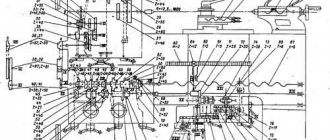
Feedbox and guitar replacement gears
An equally important element of the unit, the feed box and the guitar, their key features are discussed below:
- A set of interchangeable gears is used to change thread parameters.
- The feed box is driven by the gearbox using gears in the transmission mechanism, which includes:
- two shafts;
- five gears with different parameters;
- running roller;
- coupling;
- round nuts;
- shift handle;
- drain plug.
`
The handles on the feed box body determine the cutting parameters for workpieces. Another lever turns on the drive shaft of the unit.
Headstock and tailstock
The main element of any machine is the headstock and tailstock. Their main features and purposes are listed below:
- The purpose of the headstock is to locate the spindle assembly with the gearbox.
- I use the tailstock to secure centers; they are used to support the end surfaces of large products. Thanks to the use of the center, it is possible to significantly increase the accuracy of work.
Also, through the headstock, access to the gearbox and guitar is provided, which allows you to adjust the cutting parameter.
Apron device
The apron is part of the device that houses the slide, which is responsible for the smooth movement of the caliper. It is made of steel.
The apron structure consists of:
- handwheel;
- rack and pinion gear;
- shaft;
- worm gear;
- uterine nut;
- running roller.
Caliper design
The support secures cutting tools for ease of processing and moves it while working with metal. Four carriages form the basis of the caliper design.
In the fourth carriage, the tool holder fixes the working tools. It moves towards the third carriage, but only longitudinally.
Rotary carriage No. 3 is attached to the second carriage, the latter, in turn, is attached to the first, moving transversely.
The caliper has its own characteristics:
- It securely holds the cutting tool.
- It is located in a certain position in relation to the workpiece.
- Can move in longitudinal and transverse directions.
The support significantly expands the functionality of the machine.
Machine feed
There is a special box on the machine for mechanical feeding. Control is carried out by two handles located below the gearbox control panel. The first handle (located to the left) has three positions, which make it possible to cut three different thread pitches and obtain three caliper feed options.
The second handle allows you to activate the rotation of the lead screw or shaft. The design of the feed box has a clutch that prevents the possibility of simultaneous engagement of the screw and the shaft. To change the direction of rotation, use a handle mounted on the gearbox control panel.
The TV-6 feed box is lubricated with wicks from a container located in the upper part of the box. While the machine is operating, it is necessary to visually check the presence of oil in this container. Excess lubricant is drained through a screw plug located at the very bottom of the box.
Maintenance of the TV-6 gearbox consists of changing the oil and eliminating axial movements of the lead screw. For this purpose, there are two round nuts on the output shaft. The oil change is carried out by analogy with the gearbox - once every three months. The lead screw and shaft must be lubricated daily. They must first be cleaned of chips.
Guitar and tailstock
The torque from the gearbox is transferred to the feedbox through a gear drive called a gearbox. The latter of the TV-6 machine includes three gears. And there are no sets of replacement gears. Guitar gears are lubricated by hand and performed monthly.
The tailstock is used as a rear support for long workpieces. A quill equipped with a Morse taper is installed inside it. Thanks to it, various equipment and tools can be installed in the quill. To move it there is a flywheel connected to a screw. The alignment of the quill axis with the spindle axis is carried out using adjusting screws and a nut. To fix the headstock there is a brake controlled by a special handle.
Modifications
The main difference between the TV-7 lathe and TV-6 is the design of the gearbox. Its design includes the ability to transfer the drive belt to different pulley grooves. Due to this, the rotation range of the TV-7 machine has significantly expanded. Three additional feed selection speeds appeared in his scheme.
Another variation is the TV-4 lathe. It differs from TV-6 in its simplified frame made of steel sheet. To enhance rigidity, it is equipped with additional box-shaped amplifiers. The general diagram of the machine is shown in the image in the article.
Thanks to this frame, the weight of the machine was reduced to 280 kg. Optionally, the machine can be equipped with an adapter for connecting to a 220 Volt network. Both options are produced in the city of Rostov.