Purpose of the machines
Devices can be used when:
- There is a need for thread cutting (both internal and external);
- Drill blind and through holes;
- Countersinking is carried out;
- The ends of the workpieces are trimmed;
- It is necessary to do face and cylindrical milling.
In most cases, such equipment is used for finishing or semi-finishing. Part bodies are processed extremely rarely, but sometimes such manipulation is carried out. Boring machines are repaired in approximately the same way as lathes. This also applies to operating conditions and rules, because the machines have a similar design.
Like other numerous special types of equipment, the boring machine was designed on the basis of a lathe.
Jig boring machines
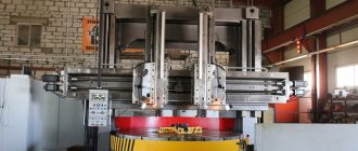
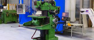
The main feature of jig boring machines (Fig. 3) is the high precision of processing parts.
Figure 3. Jig boring machine.
Figure 3. Jig boring machine.
Increased processing accuracy is achieved through the use of various high-precision mechanisms for calculating the coordinates along which the cutter moves. There are several main methods for calculating coordinates implemented on jig boring machines:
- inductive;
- mechanical;
- optical-mechanical;
- electronic.
The spindle on the machines of this subgroup is located vertically. But sometimes there are models with a horizontal spindle. The spindle head, in addition to changing the speed and direction of rotation, also carries out a working feed, increasing or decreasing the depth of penetration of the cutter into the part.
The table has two degrees of freedom. A part fixed on a table can move in the longitudinal and transverse directions. Moreover, the magnitude of these movements is controlled with high accuracy by the coordinate system.
Also, on jig boring machines, in addition to performing the entire range of operations characteristic of boring group machines, marking operations are performed.
Equipment types
As a rule, there are three main types used in production:
- Horizontal boring machines;
- Coordinate boring;
- Diamond boring.
The first two types are the most common.
Horizontal boring machines
The main feature of such equipment is the horizontal position of the spindle, which allows it to extend. Thus, it is possible to make a hole even in inaccessible places of large parts (booms, frames, metal structures).
The main movement of the unit is rotational-translational, performed through a spindle. Not only the tools move, but also the workpieces themselves. If the need arises, you can change the feed and speed during operation. Sometimes a special substrate is used when feeding.
Depending on the configuration, there may be additional auxiliary movements:
- The spindle head moves along a vertical axis;
- The table moves along previously specified coordinates.
In some models, the design provides that the rest and rear pillar can move. They can be used for processing products made of cast iron or cast steel.
Boring machines are used to work with complex parts that contain numerous holes, grooves, and ledges. According to their layout they are divided into:
- Models with a spindle no more than 125 mm. Designed for processing small workpieces. The table is movable along two axes, the boring heads move in the vertical direction.
- Models with spindle 100−200 mm. Allows you to work with medium and large parts. The table moves only along one axis.
- Models with spindle 125−320 mm. With their help you can process very large parts. The table is motionless.
Jig boring machines
Such machines are designed for drilling holes according to certain parameters. Perform operations on various workpieces. High-precision processing is obtained due to the presence of special devices: electronic, mechanical and optical. In addition, rotary tables also help to achieve the desired results: the hole can be made without moving the part. The models are not too large and take up little usable space.
Diamond boring type models
They allow fine boring of cylindrical surfaces. If there are additional components, then conical surfaces and ends with rotation grooves can be processed. It is permissible to drill a pair of holes that have parallel axes. Machines of this type can be:
- Vertical;
- Sloping;
- Combined;
- Horizontal, the table is movable.
Horizontal boring machines
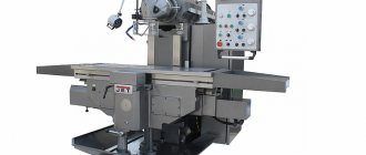
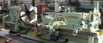
The main distinctive feature of a horizontal boring machine (Fig. 1) is the horizontal arrangement of the spindle. This type of machine is somewhat reminiscent of a conventional screw-cutting lathe. But there are several key differences in a horizontal boring machine. Firstly, the tailstock is missing. Instead of the tailstock, a movable rest is installed. Secondly, the faceplate with which the spindle is equipped has the ability to shift the cutter relative to the axis of rotation, which is not typical for a lathe. Thirdly, there is a table on which the part can be fixed.
Figure 1. Horizontal boring machine
Figure 1. Horizontal boring machine
Let's look at the main components and elements that make up a standard horizontal boring machine.
- Rear pillar. It is designed to attach a movable rest to it. Can be moved on the bed guides. Has a lever to lock the position.
- Lunette. This device is designed to hold the tail part of the workpiece if its length does not allow for reliable fastening to the table. Serves as an additional attachment point. The lunette can move in a vertical plane. Movement in the horizontal plane is carried out through the movement of the rear pillar.
- Front pillar. The main support on which the working part of the machine is mounted is the spindle head. On the front pillar there are vertical guides along which the headstock moves.
- Caliper. This element of a horizontal boring machine serves to feed the cutter to the surface of the workpiece. The support has the ability to move longitudinally in a horizontal plane along the axis of rotation.
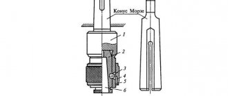
- Faceplate (Fig. 2). Unlike the standard faceplate of lathe group machines, it is used to secure the boring cutter in it. It has the ability to shift the cutter relative to the axis of rotation. This allows one tool to perform various boring operations.
- Spindle. Transmits rotational motion from the gearbox to the faceplate.
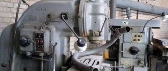
- Grandma. The working moving part of a horizontal boring machine. Inside the headstock there is an electric motor, gearbox and guides for axial movement of the caliper.
- Remote Control. Includes buttons for changing operating speed, reverse, automatic feed settings and emergency stop.
- Table. Serves for arranging and securing massive parts of small dimensions on it.
- Sled. Used to move the table.
- Bed. It is the base of the machine. On the bed there are two racks and a table. Sometimes the bed has the ability to adjust the installation level of the machine.
Figure 2. Boring machine faceplate.
Figure 2. Boring machine faceplate.
Today, horizontal boring machines that are equipped with a numerical control module are becoming increasingly common.
What to pay attention to
Before making a purchase, pay attention to a number of parameters, in particular:
- Spindle dimensions;
- Maximum permissible weight and dimensions of workpieces;
- Desktop diameter;
- The maximum possible level of movement along the axes;
- Speed range;
- Feed interval;
- Engine power.
Engine power is one of the important indicators on which the processing speed of parts will depend.
Boring machines belong to special and sought-after equipment; they are indispensable in many cases, especially when it is necessary to achieve jewelry precision and maximum productivity. If an enterprise is in dire need of mechanisms of this type, it will be able to find suitable options on the domestic market without much effort.
Machining on boring machines
Boring
- a type of processing of holes previously obtained by some other method, using boring cutters. Boring is used to machine internal (cylindrical, end and threaded), external (end and cylindrical) surfaces of rotation, as well as flat surfaces in various workpieces. This type of processing is most widely used when machining holes in body parts.
The main movement when boring is the rotation of the tool. The feed movement can be performed by the workpiece or the tool. The shaping of surfaces occurs using the trace method.
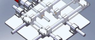
The main types of boring machines: jig boring, horizontal boring and diamond boring. Jig boring machines allow you to process holes in various workpieces with high accuracy of shape, size and relative position. By design, such machines are single-column (Fig. 3.5) and double-column.
The table 1 of the jig boring machine can move along the guides of the slide 2, and the slide, in turn, along the horizontal guides of the frame makes longitudinal and transverse adjustment movements, respectively. The required processing quality is achieved through the coordinate placement of workpieces relative to the tool, carried out using special optical devices with an accuracy of several micrometers.
Fig.3.5. General view of the jig boring machine
Horizontal boring machines are most widespread at machine-building enterprises (Fig. 3.6). They are used mainly for processing blanks of body parts.
On the frame 1 of the horizontal boring machine, the front post 2 is fixedly fixed, along the vertical guides of which the spindle headstock 3 with the faceplate 4, the radial support 5 and the spindle 6 moves. On the horizontal guides of the frame, the rear post 7 with the support rest is installed in the desired position and secured. A table 11 moves along the longitudinal guides of the frame, in the transverse guides of which a slide 10 with a rotary table 9 and a workpiece mounted on it moves. The tool is fixed in the spindle or on the faceplate and together with them makes the main rotational movement. The feed motion can be performed by either the workpiece or the tool. In the first case, the workpiece moves transversely along with the slide or longitudinally along with the table. When the caliper moves axially, the radial caliper moves radially, or the spindle head moves vertically, the cutting tool performs the feed movement along with them.
Fig.3.6. General view of a horizontal boring machine.
Jig boring and horizontal boring machines are produced with both manual and program control. On CNC boring machines, either part of the processing cycle is programmed and automatically executed, for example, installing a tool at given coordinates, fixing moving parts of the machine before processing; or the entire cycle occurs automatically.
On diamond boring machines (Fig. 3.7), cylindrical holes are processed with high precision, as well as end surfaces in body workpieces of small overall dimensions. Processing is carried out according to an automatic cycle. These machines are used in large-scale and mass production.
Fig.3.7. General view of the diamond boring machine.
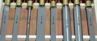
Depending on the type of surfaces processed on boring machines, various types of cutting tools are used: boring cutters, cutters, drills, countersinks, reamers, taps. The most widely used are various types of boring cutters: through, scoring, groove, threaded. Structurally, they can be made in the form of rod or plate cutters, cutting heads or cutting blocks. An auxiliary tool for securing them is special single- or double-support mandrels. The mandrels are fixed in the spindle of the boring machine.
Rod cutters are installed on a cantilever or two-support mandrel; the specified diameter of the hole being machined is ensured by regulating the extension of the cutter. Sometimes, to bore multi-stage holes, several rod cutters are attached to one mandrel. In each specific case, the location and method of fastening the cutter depends on the shape of the hole being machined.
Double-edged lamellar cutters are installed in mandrels, cantilever or two support ones; In this case, different design methods for fastening the cutters are used, for example, hinged or wedge. In boring blocks, which are a prefabricated structure, the cutting element is cutters or carbide inserts installed in the body. The blocks provide the ability to adjust the cutters depending on the size of the hole being machined. Boring blocks are fixed on mandrels.
Boring heads are a prefabricated structure with two rod boring tools. The boring head, depending on the shape and size of the surfaces being processed, can be installed on the mandrel in any position along the length. In addition to holes, end surfaces are also machined using boring heads.
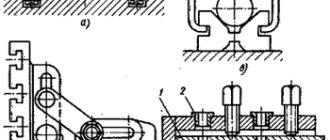
Figure 3.8 shows some schemes for processing cylindrical and flat surfaces on boring machines.
Boring of short cylindrical surfaces located close to the spindle is carried out using boring cutters mounted on a cantilever mandrel (Fig. 3.8a).
Simultaneous machining of two coaxial large-diameter holes with boring heads on a two-support mandrel occurs according to the scheme shown in Fig. 3.8b. It is also possible, when working according to the indicated schemes, instead of longitudinal feed, to sometimes use axial feed of the tool.
| a b |
| in d d |
| e f z |
Fig.3.8. Schemes of surface treatment on boring machines
It is advisable to process internal cylindrical surfaces of very large diameter with a boring cutter mounted on the faceplate of the machine in a mandrel (Fig. 3.8c). The main movement is performed by the tool, rotating together with the faceplate. Short outer cylindrical surfaces are processed in a similar way (Fig. 3.8e).
External end surfaces, internal grooves and other similar elements of workpieces are processed with cutters of appropriate designs. The cutter, fixed in a radial support, rotates and moves with radial feed (Fig. 3.8g). On boring machines, you can also mill vertical planes with an end milling cutter (Fig. 3.8, h); mill the grooves with end mills, and when the groove is positioned vertically, the tool feeds, and when the groove is positioned horizontally, the feed is made by the workpiece. On a horizontal boring machine equipped with special fixtures and devices, it is also possible to process conical and shaped surfaces; cut threads with thread cutters and taps.
Boring
- a type of processing of holes previously obtained by some other method, using boring cutters. Boring is used to machine internal (cylindrical, end and threaded), external (end and cylindrical) surfaces of rotation, as well as flat surfaces in various workpieces. This type of processing is most widely used when machining holes in body parts.
The main movement when boring is the rotation of the tool. The feed movement can be performed by the workpiece or the tool. The shaping of surfaces occurs using the trace method.
The main types of boring machines: jig boring, horizontal boring and diamond boring. Jig boring machines allow you to process holes in various workpieces with high accuracy of shape, size and relative position. By design, such machines are single-column (Fig. 3.5) and double-column.
The table 1 of the jig boring machine can move along the guides of the slide 2, and the slide, in turn, along the horizontal guides of the frame makes longitudinal and transverse adjustment movements, respectively. The required processing quality is achieved through the coordinate placement of workpieces relative to the tool, carried out using special optical devices with an accuracy of several micrometers.
Fig.3.5. General view of the jig boring machine
Horizontal boring machines are most widespread at machine-building enterprises (Fig. 3.6). They are used mainly for processing blanks of body parts.
On the frame 1 of the horizontal boring machine, the front post 2 is fixedly fixed, along the vertical guides of which the spindle headstock 3 with the faceplate 4, the radial support 5 and the spindle 6 moves. On the horizontal guides of the frame, the rear post 7 with the support rest is installed in the desired position and secured. A table 11 moves along the longitudinal guides of the frame, in the transverse guides of which a slide 10 with a rotary table 9 and a workpiece mounted on it moves. The tool is fixed in the spindle or on the faceplate and together with them makes the main rotational movement. The feed motion can be performed by either the workpiece or the tool. In the first case, the workpiece moves transversely along with the slide or longitudinally along with the table. When the caliper moves axially, the radial caliper moves radially, or the spindle head moves vertically, the cutting tool performs the feed movement along with them.
Fig.3.6. General view of a horizontal boring machine.
Jig boring and horizontal boring machines are produced with both manual and program control. On CNC boring machines, either part of the processing cycle is programmed and automatically executed, for example, installing a tool at given coordinates, fixing moving parts of the machine before processing; or the entire cycle occurs automatically.
On diamond boring machines (Fig. 3.7), cylindrical holes are processed with high precision, as well as end surfaces in body workpieces of small overall dimensions. Processing is carried out according to an automatic cycle. These machines are used in large-scale and mass production.
Fig.3.7. General view of the diamond boring machine.
Depending on the type of surfaces processed on boring machines, various types of cutting tools are used: boring cutters, cutters, drills, countersinks, reamers, taps. The most widely used are various types of boring cutters: through, scoring, groove, threaded. Structurally, they can be made in the form of rod or plate cutters, cutting heads or cutting blocks. An auxiliary tool for securing them is special single- or double-support mandrels. The mandrels are fixed in the spindle of the boring machine.
Rod cutters are installed on a cantilever or two-support mandrel; the specified diameter of the hole being machined is ensured by regulating the extension of the cutter. Sometimes, to bore multi-stage holes, several rod cutters are attached to one mandrel. In each specific case, the location and method of fastening the cutter depends on the shape of the hole being machined.
Double-edged lamellar cutters are installed in mandrels, cantilever or two support ones; In this case, different design methods for fastening the cutters are used, for example, hinged or wedge. In boring blocks, which are a prefabricated structure, the cutting element is cutters or carbide inserts installed in the body. The blocks provide the ability to adjust the cutters depending on the size of the hole being machined. Boring blocks are fixed on mandrels.
Boring heads are a prefabricated structure with two rod boring tools. The boring head, depending on the shape and size of the surfaces being processed, can be installed on the mandrel in any position along the length. In addition to holes, end surfaces are also machined using boring heads.
Figure 3.8 shows some schemes for processing cylindrical and flat surfaces on boring machines.
Boring of short cylindrical surfaces located close to the spindle is carried out using boring cutters mounted on a cantilever mandrel (Fig. 3.8a).
Simultaneous machining of two coaxial large-diameter holes with boring heads on a two-support mandrel occurs according to the scheme shown in Fig. 3.8b. It is also possible, when working according to the indicated schemes, instead of longitudinal feed, to sometimes use axial feed of the tool.
| a b |
| in d d |
| e f z |
Fig.3.8. Schemes of surface treatment on boring machines
It is advisable to process internal cylindrical surfaces of very large diameter with a boring cutter mounted on the faceplate of the machine in a mandrel (Fig. 3.8c). The main movement is performed by the tool, rotating together with the faceplate. Short outer cylindrical surfaces are processed in a similar way (Fig. 3.8e).
External end surfaces, internal grooves and other similar elements of workpieces are processed with cutters of appropriate designs. The cutter, fixed in a radial support, rotates and moves with radial feed (Fig. 3.8g). On boring machines, you can also mill vertical planes with an end milling cutter (Fig. 3.8, h); mill the grooves with end mills, and when the groove is positioned vertically, the tool feeds, and when the groove is positioned horizontally, the feed is made by the workpiece. On a horizontal boring machine equipped with special fixtures and devices, it is also possible to process conical and shaped surfaces; cut threads with thread cutters and taps.
Technical characteristics of the machine 2431
The technical characteristics of the machine 2431 are the main indicator of the machine’s suitability for performing certain jobs. For jig boring machines, the main characteristics are:
- table working surface size
- largest drilling diameter
- largest boring diameter
- spindle overhang
- distance from the end of the spindle to the working surface of the table
- spindle revolutions per minute
Below is a table with the technical characteristics of the jig boring machine 2431. More detailed technical characteristics of the jig boring machine can be found in the passport of the machine 2431
| Quantities | ||
| Accuracy class according to GOST 8-71 | WITH | |
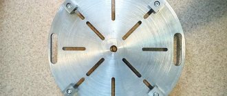
| Table working surface width | mm | 320 |
| Table working surface length | mm | 560 |
| Number of T-slots | 5 | |
| Distance between grooves | mm | 63 |
| Groove width | mm | 12 |
| Maximum longitudinal movement of the table | mm | 400 |
| Maximum lateral movement of the table | mm | 250 |
| Adjusting the table feed | steps | 16 |
| Table feed limits | mm/min | 22…600 |
| Table speed value | mm/min | 1600 |
| Distance from spindle axis to column | mm | 375 |
| The shortest distance from the end of the spindle to the working surface of the table | mm | 120 |
| The greatest distance from the end of the spindle to the working surface of the table | mm | 500 |
| Maximum spindle sleeve stroke | mm | 150 |
| Maximum movement of the spindle head | mm | 230 |
| Number of spindle speed steps | 17 | |
| Spindle speed limits | mm | 75-3000 |
| Number of spindle feed rates | 6 | |
| Spindle feed | mm/rev | 0,02;0,03;0,06;0,08;0,12;0,2 |
| Spindle inner taper | Morse 3 | |
| Outer cone diameter | 60 | |
| Outer cone taper | 7:24 | |
| Largest drilling diameter for steel in solid material | mm | 18 |
| Largest boring diameter | mm | 125 |
| The largest mass of the workpiece | kg | 250 |
| Overall dimensions of the machine (LxWxH) | mm | 2120x1250x2430 |
| Total weight of the machine | kg | 3735 |
Attention! The technical specifications given in the above table are for reference only. Machines produced by different manufacturers and in different years may have characteristics that differ from those given in the table.