MINISTRY OF COMMUNICATIONS OF THE UNION SSR
SPECIALIZED DESIGN AND TECHNOLOGICAL BUREAU OF CONSTRUCTION COMMUNICATION EQUIPMENT
I APPROVED
Deputy head of the GRSS
A. I. Polnikov
"27" March 1989
TECHNOLOGICAL MAP FOR INSTALLATION OF METAL STRUCTURES OF ATS BY ARC WELDING METHOD
MOSCOW - 1989
1.1. The technological map has been developed for the installation of metal structures of automatic telephone exchanges using the arc welding method using welding equipment and fixtures. The technological map can be used as a guide for the technologically correct performance of work when welding assemblies and parts for various purposes in the workshop, cross-country, mine and power supply installations.
1.2. The scope of work performed during the installation of metal structures of automatic telephone exchanges using the welding method, discussed in the technological map, includes:
— welding open-type gutters in straight sections at the butt and welding them to wall brackets or angles;
— welding of open gutters at an angle of 90°, welding of gutters to wall angles when passing through a wall, welding of gutters vertically on brackets in the wall;
— welding of open-type gutters during their descents in the frame row and when passing through the floor slab;
— installation and welding of brackets in the shaft;
— installation of metal structures by welding in the shaft and cross-section;
— fastening by welding of main gutters to ordinary gutters and the main gutter in a span of up to 2.5 m;
— fastening by welding of open-type air channels for cross-connecting wires and frames with test sockets in the subscriber distribution box.
1.3. Work on welding components and parts of metal structures can be carried out in the premises of a car showroom, a mine, a crossover, a rectifier and a battery. When performing welding work, especially in winter, flow-exhaust ventilation must be turned on, and when performing welding work in a mine, it is recommended to use portable ventilation devices.
In the battery room, welding of metal structures must be completed before installation of battery vessels begins. When performing welding work in rooms with installed equipment, the equipment must be protected from drops of metal and scale.
1.4. When linking the technological map to a specific object and construction conditions, the scope of work, calculation of labor costs, technical and economic indicators and mechanization means are specified, taking into account the maximum use of the existing fleet of installation mechanisms and devices.
APPLICATION AREA
1. A standard flow chart has been developed for a set of works on the installation of metal trusses.
2. The scope of work sequentially performed during the installation of metal structures includes:
— geodetic breakdown of the location of metal structures;
— installation of finished metal structures;
— alignment and fastening of metal structures in the design position.
3. Work should be carried out in accordance with the requirements of the following regulatory documents:
SNiP II-23-81*. Steel structures;
SNiP 3.03.01-87. Load-bearing and enclosing structures;
RD 34.15.132-96 Welding and quality control of welded joints of metal structures of buildings during the construction of industrial facilities.
The technological map is intended for use in the development of Work Performance Projects (WPP), Construction Organization Projects (COP), other organizational and technological documentation, as well as for the purpose of familiarizing workers and engineers with the rules for carrying out work on installing roofing from asbestos-cement sheets.
When linking the map to specific objects and conditions of work, the volume of work, the need for material and technical resources, the calculation of labor costs and the work schedule are subject to clarification. The technological map has been developed in accordance with the requirements of the following regulatory documents:
1. SP 48.13330.2011 “Construction organization”;
2. GOST 24297-87 “Incoming inspection of products. Basic provisions";
3. SNiP 12-03-2001 “Labor safety in construction. Part 1. General requirements";
4. SNiP 12-04-2002 “Labor safety in construction. Part 2. Construction production";
5. SP 12-135-2003 “Labor safety in construction. Industry standard instructions on labor protection."
6. PPB 01-03 “Fire Safety Rules in the Russian Federation”;
7. SanPiN 2.2.4.548-96 “Hygienic requirements for the microclimate of industrial premises”
8. GOST 7502-98 “Metal measuring tapes. Technical conditions".
9. GOST 9416-83 “Construction levels. Technical conditions".
10. GOST 12.4.011-89 SSBT “Means for protecting workers. General requirements and classification";
11. GOST 12.4.103-83 SSBT “Special protective clothing, personal protective equipment for legs and arms. Classification";
12. ENiR “Unified standards and prices for construction, installation and repair work. A common part";
13. “Guide to the development of technological maps in construction” (M.: TsNIIOMTP, 2004);
2.1. Requirements for the quality of previous work
Before installing roof trusses, there must be:
- all columns and connections are finally secured
- must be delivered to the workplace: installation equipment, fixtures and tools.
— appointment of a person responsible for high-quality and safe work;
— production and technical documentation was received;
— permits to carry out work have been obtained from the organization operating this structure;
— briefings on safety precautions and industrial sanitation were carried out;
— construction of entrances to the work site and planning of the installation site;
— mobile trailers were installed for storing tools and household needs;
— workplaces have been prepared and equipped with protective equipment, medical kits and fire-fighting equipment;
— agreed upon delivery schedules for equipment, products and materials;
— preparation of places for storing materials, inventory and other necessary equipment;
— tools, fixtures, and equipment were selected and delivered to the installation site and their technical condition was checked;
— geodetic breakdown of the transition axis with the execution of an act with diagrams of the location of benchmarks and other geodetic signs;
— construction zones are fenced off with warning signs illuminated at night;
— provided with communications for operational dispatch control of work;
— the construction site was provided with fire-fighting equipment and alarm systems;
— an act of readiness of the facility for work has been drawn up.
— before lifting, metal trusses should be cleaned of dirt, ice, rust, and, if necessary, primed and painted.
— check that the geometric dimensions correspond to the drawing and that there are no burrs.
— preparation of the joining surfaces consists of cleaning them from dirt, rust, snow, ice, oil and dust.
- use a file or chisel to cut off burrs on the edges of parts, and also carefully straighten any irregularities, dents, or bent parts of the connection that could have occurred during transportation of structures, as well as during their loading and unloading.
— representatives of the construction organization (foreman) and the customer’s organization (technical supervision), before the start of installation work, must jointly inspect and sign an act for hidden work (accept factory-made structures).
2.3. Work technology
Sequence of work:
1. Before lifting, metal trusses should be cleaned of dirt, ice, rust, and, if necessary, primed and painted. Check that the geometric dimensions correspond to the drawing and that there are no burrs. Preparation of the joining surfaces consists of cleaning them from dirt, rust, snow, ice, oil and dust. In addition, it is necessary to file or cut off the burrs on the edges of the parts with a chisel, and also carefully straighten any irregularities, dents, or bent parts of the connection that could have occurred during transportation of the structures, as well as during their loading and unloading.
2. Before lifting to the truss, guys are attached (ropes that will allow the slinger to control the beam while lifting, while in a safe area).
3. The slinger slings the truss and then, leaving the danger zone, gives a signal to the crane operator to begin lifting. The metal structure supplied by crane to the installation site should be kept from swinging and turning by hemp guys.
4. The trusses should be brought to the installation site in the design position by a crane from the side opposite to where the slingers are located.
6. The raised element is lowered above the installation site no more than 0.3 m above the design position, after which the slingers approach the installation site (climb onto towers) and point it at the installation site.
7. The element is fastened using a bolted connection.
8. The metal structure element is unfastened.
— Before installing the structure, it is necessary to equip: rafter trusses with a safety rope and guys.
— For slinging trusses and beams, traverses equipped with grips with remote automatic or semi-automatic slinging should be used.
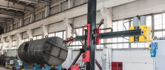
— When lifting the truss, its position in space is adjusted using guy ropes. At a height of about 0.6 m above the support areas, the truss is accepted by installers (located on the installation platforms attached to the columns), guided along the axial marks and installed in the design position. Then the embedded parts are welded, after which the truss is unfastened. For the installation of beams and trusses, mobile and self-propelled telescopic and articulated towers and lifts are often used.
Figure 2 - Truss installation diagram.
TECHNOLOGY AND ORGANIZATION OF WORK EXECUTION
2.1. Requirements for the quality of previous work
Before installing roof trusses, there must be:
- all columns and connections are finally secured
- must be delivered to the workplace: installation equipment, fixtures and tools.
— appointment of a person responsible for high-quality and safe work;
— production and technical documentation was received;
— permits to carry out work have been obtained from the organization operating this structure;
— briefings on safety precautions and industrial sanitation were carried out;
— construction of entrances to the work site and planning of the installation site;
— mobile trailers were installed for storing tools and household needs;
— workplaces have been prepared and equipped with protective equipment, medical kits and fire-fighting equipment;
— agreed upon delivery schedules for equipment, products and materials;
— preparation of places for storing materials, inventory and other necessary equipment;
— tools, fixtures, and equipment were selected and delivered to the installation site and their technical condition was checked;
— geodetic breakdown of the transition axis with the execution of an act with diagrams of the location of benchmarks and other geodetic signs;
— construction zones are fenced off with warning signs illuminated at night;
— provided with communications for operational dispatch control of work;
— the construction site was provided with fire-fighting equipment and alarm systems;
— an act of readiness of the facility for work has been drawn up.
— before lifting, metal trusses should be cleaned of dirt, ice, rust, and, if necessary, primed and painted.
— check that the geometric dimensions correspond to the drawing and that there are no burrs.
— preparation of the joining surfaces consists of cleaning them from dirt, rust, snow, ice, oil and dust.
- use a file or chisel to cut off burrs on the edges of parts, and also carefully straighten any irregularities, dents, or bent parts of the connection that could have occurred during transportation of structures, as well as during their loading and unloading.
— representatives of the construction organization (foreman) and the customer’s organization (technical supervision), before the start of installation work, must jointly inspect and sign an act for hidden work (accept factory-made structures).
2.2 General instructions for work
Work on the installation of the metal frame of the building in the developed technical complex is planned to be carried out using a KS-45722 truck crane with a three-section boom 8.75 - 20.75 m long and a maximum lifting capacity Q
= 16 t.
Use construction tours type TT1600 as scaffolding equipment.
Before starting frame installation work, contractors must:
— deliver metal structures from the manufacturer’s plant to the construction site,
— carry out the layout (storage) of metal frame elements directly at the places of their installation.
The unloading of trusses on site, the layout and installation of elements is usually carried out by a truck crane within the range of the installation crane. Installation of these structures can be carried out with preliminary layout of the elements (or directly from vehicles). The layout of trusses and beams is carried out in such a way that a crane from the assembly parking lot can install them in the design position without changing the boom radius. To ensure the stability of the mounted elements on the ground, they are stored in special cassettes. When structures are delivered to the site in significant quantities, temporary storage in group cassettes without layout in the installation area is allowed. If it is intended to install crane beams in an independent flow, then it is preferable to install truss trusses with them in the same flow.
Figure 1 - Truss slinging diagram
2.3. Work technology
Sequence of work:
1. Before lifting, metal trusses should be cleaned of dirt, ice, rust, and, if necessary, primed and painted. Check that the geometric dimensions correspond to the drawing and that there are no burrs. Preparation of the joining surfaces consists of cleaning them from dirt, rust, snow, ice, oil and dust. In addition, it is necessary to file or cut off the burrs on the edges of the parts with a chisel, and also carefully straighten any irregularities, dents, or bent parts of the connection that could have occurred during transportation of the structures, as well as during their loading and unloading.
2. Before lifting to the truss, guys are attached (ropes that will allow the slinger to control the beam while lifting, while in a safe area).
3. The slinger slings the truss and then, leaving the danger zone, gives a signal to the crane operator to begin lifting. The metal structure supplied by crane to the installation site should be kept from swinging and turning by hemp guys.
4. The trusses should be brought to the installation site in the design position by a crane from the side opposite to where the slingers are located.
6. The raised element is lowered above the installation site no more than 0.3 m above the design position, after which the slingers approach the installation site (climb onto towers) and point it at the installation site.
7. The element is fastened using a bolted connection.
8. The metal structure element is unfastened.
— Before installing the structure, it is necessary to equip: rafter trusses with a safety rope and guys.
— For slinging trusses and beams, traverses equipped with grips with remote automatic or semi-automatic slinging should be used.
— When lifting the truss, its position in space is adjusted using guy ropes. At a height of about 0.6 m above the support areas, the truss is accepted by installers (located on the installation platforms attached to the columns), guided along the axial marks and installed in the design position. Then the embedded parts are welded, after which the truss is unfastened. For the installation of beams and trusses, mobile and self-propelled telescopic and articulated towers and lifts are often used.
Figure 2 - Truss installation diagram.
REQUIREMENTS FOR QUALITY AND ACCEPTANCE OF WORK
Incoming control
Quality control of the materials used is entrusted to the construction laboratory, and the execution of work is the responsibility of the foreman or foreman.
The materials used for the installation of coatings must comply with the requirements of the technical specifications. To do this, a random check (incoming inspection) is carried out on each batch of materials received at the construction site. If materials do not comply with the requirements of regulatory documents, the batch is rejected and returned to the supplier.
The results of the incoming inspection of the materials used must be recorded in the protocols of the testing laboratories, and the data of the acceptance inspection are recorded in the work logs of the organization performing the installation of the frame, profiled sheet and sandwich panels, as well as in acts for hidden work and inspection reports for critical structures.
Operational control
| № | Name of operations subject to control | Quality control of performed operations | |||
| Compound | Way | Time | Involved services | ||
| 1 | 2 | 3 | 4 | 5 | 6 |
| 1 | Preparatory work | Correct storage of structures. Availability of passports and quality certificates. Completeness of structures. Compliance of structural elements with the project. Presence of external defects. | Visual steel tape measure | Before installation work begins | — |
| 2 | Preparation of installation sites | Marking the support areas of the columns and the assembly tower. Applying alignment axes and marks to the support areas of columns and the assembly tower. | Theodolite, steel meter and tape measure | Before installation work begins | Geodetic |
| 3 | Enlarged assembly of semi-trusses | Compliance of assembly technology with the work project. Displacement of truss elements in support nodes. Compliance of truss sizes with the project. Quality of welds. | Theodolite, tape measure and meter | During installation work | Geodetic |
| 4 | Installation of farms | Correct and reliable slinging and temporary fastening. Compliance of installation technology with the work project. Deviations from the centers of the tower support platforms. Vertical installation of semi-trusses. Distance between truss axles. Displacement of the lower chord in the docking unit. Quality of welds. | Visually with theodolite, steel tape measure and meter | During installation work | Geodetic |
Acceptance control and as-built documentation
An assessment of the work performed, the results of which affect the safety of the facility and its compliance with operational characteristics, but in accordance with the adopted technology becomes unavailable for control after the start of subsequent work, must be carried out according to certificates of inspection of hidden work.
An assessment of the work performed, the results of which affect the safety of the facility and its compliance with operational characteristics, must be carried out according to inspection reports of critical structures.
When installing the frame, intermediate acceptance of completed elements and final acceptance of the frame as a whole are carried out. Quality control of the materials used is entrusted to the construction laboratory, and the execution of work is the responsibility of the foreman or foreman.
The materials used for mounting the frame must meet the requirements of the technical specifications. To do this, a random check (incoming inspection) is carried out on each batch of materials received at the construction site. If materials do not comply with the requirements of regulatory documents, the batch is rejected and returned to the supplier.
The results of the incoming inspection of the materials used must be recorded in the reports of the testing laboratories, and the data of the acceptance inspection of individual welds must be recorded in the logs of the organization performing the installation of the frame.
Defects or deviations from the design discovered during inspection of joints of structures, walls made of sandwich panels, abutments, flooring made of profiled sheets must be corrected before starting work on the installation of overlying, adjacent or subsequent structures.
Acceptance of the completed frame structure is accompanied by a thorough inspection of its surface, especially the places of bolted connections, the correct installation of elements, and the installation sequence.
The work is considered completed and is subject to payment when the customer, general contractor and contractor sign the as-built documentation.
4.1. General provisions
When carrying out installation work, it is necessary to comply with the requirements of the following regulatory documents:
— SNiP 12-03-2001 “Labor safety in construction. Part 1. General requirements";
— SNiP 12-04-2002 “Labor safety in construction. Part 2. Construction production";
— SP 12-135-2003 “Labor safety in construction. Industry standard instructions on labor protection."
When several organizations are working at a construction site, it is necessary to provide for occupational safety measures in accordance with the “Regulations on the relationship between organizations - general contractors and subcontractors.”
All new workers entering organizations (enterprises) can be allowed to work only after undergoing introductory training and initial training at the workplace on labor protection, regardless of the nature and degree of danger of production. All types of briefing and training on occupational safety should be carried out and registered in accordance with GOST 12.0.004-79 “Organization of occupational safety training for workers.”
Workers, managers, specialists and employees must be provided with special clothing, safety footwear and other personal protective equipment that comply with GOST 12.4.011.
Workplaces and approaches to them must be illuminated in accordance with the requirements of GOST 12.1.046 (see Table 1, section 2.3. “Requirements for the organization of work meta” of this TTK).
If violations of labor safety standards and rules are detected, workers must take measures to eliminate them on their own, and if this is impossible, stop work and inform the official.
In the event of a threat to the safety and health of workers, responsible persons are obliged to stop work and take measures to eliminate the danger, and, if necessary, ensure the evacuation of people to a safe place.
SAFETY AND OCCUPATIONAL HEALTH REQUIREMENTS
4.1. General provisions
When carrying out installation work, it is necessary to comply with the requirements of the following regulatory documents:
— SNiP 12-03-2001 “Labor safety in construction. Part 1. General requirements";
— SNiP 12-04-2002 “Labor safety in construction. Part 2. Construction production";
— SP 12-135-2003 “Labor safety in construction. Industry standard instructions on labor protection."
When several organizations are working at a construction site, it is necessary to provide for occupational safety measures in accordance with the “Regulations on the relationship between organizations - general contractors and subcontractors.”
All new workers entering organizations (enterprises) can be allowed to work only after undergoing introductory training and initial training at the workplace on labor protection, regardless of the nature and degree of danger of production. All types of briefing and training on occupational safety should be carried out and registered in accordance with GOST 12.0.004-79 “Organization of occupational safety training for workers.”
Workers, managers, specialists and employees must be provided with special clothing, safety footwear and other personal protective equipment that comply with GOST 12.4.011.
Workplaces and approaches to them must be illuminated in accordance with the requirements of GOST 12.1.046 (see Table 1, section 2.3. “Requirements for the organization of work meta” of this TTK).
If violations of labor safety standards and rules are detected, workers must take measures to eliminate them on their own, and if this is impossible, stop work and inform the official.
In the event of a threat to the safety and health of workers, responsible persons are obliged to stop work and take measures to eliminate the danger, and, if necessary, ensure the evacuation of people to a safe place.
4.2. Safety precautions when working with electrical machines
The rated voltage of Class I electrical machines should not exceed 220 V for DC machines and 380 V for AC machines.
The machines should be used only in accordance with the intended purpose specified in the passport. The use of hand-held electric machines of class G in construction is prohibited.
Before starting work you should:
— determine storage locations for materials, equipment, and tools at the construction site;
— provide all workers with personal protective equipment.
When working with electrical machines you must:
— monitor the condition of the cable insulation, the absence of sharp bends in the hoses, the formation of loops, and the cable and hose getting under the wheels;
— connection (disconnection) of auxiliary equipment (step-down transformers, frequency converters, protective circuit-breakers), as well as faults in them, should only be carried out by the electrician on duty.
4.3. Safety precautions when performing installation work
General safety requirements
1.1. Individuals who are at least 18 years old, who have professional training, who have undergone introductory instructions and on-the-job occupational safety instructions, a medical examination and who are recognized as fit for health reasons for these types of work, who have at least 1 year of experience in steeplejack work and a tariff grade are allowed to perform independent steeplejack work. not lower than 3rd.
1.2. It is not allowed to carry out installation work at height in open areas with a wind speed of 15 m/s or more, during icy conditions, thunderstorms or fog that excludes visibility within the work front.
1.3. Familiarize all workers with the organization of the workplace, developed in technological maps, according to the profile of the work performed, against signature.
1.4. When carrying out construction and installation work, comply with the requirements of GOST 12.3.002-75 and provide for a technological sequence of production operations so that the previous operation does not constitute a source of industrial hazard when performing subsequent ones.
1.5 Lifting devices, slings and other equipment must be equipped with tags indicating the load capacity. They are tested for double load at least twice a year, and based on the results of the examination, special passports are issued.
1.6 Warning posters must be posted at the construction site and signal and work lighting must be installed. All workplaces must be illuminated in the evening and at night.
1.7 For the movement of people on a construction site, the width of passages must be at least 1 m if loads are not carried along these passages, and at least 2 m if loads are carried. In passages located on slopes or slopes with a slope of more than 20°, install stairs or stepladders at least 0.3 m wide with one-sided strong railings 1 m high.
1.8 All passages and driveways must be constantly cleared of debris and construction materials, and in winter of snow and ice and sprinkled with sand, slag or ash.
1.9 Sites for storing materials must be carefully planned and leveled, and in winter cleared of snow and ice. To remove surface water, it is necessary to install drainage systems.
1.10 Stacks should be stacked and dismantled mechanically.
Safety requirements before starting work.
2.1. Inspect and put on special clothing. shoes, helmet, personal protective equipment, safety belt.
2.2. Check the condition of the workplace, the presence of scaffolding, the serviceability of lifting devices, their compliance with the work plan, the presence and serviceability of tools.
2.3. Make sure that there are safety signs (signal fencing) indicating dangerous zones near the building and dangerous zones near the places where cargo is moved by cranes in accordance with the PPR.
2.4 Conduct a briefing with an entry in the briefing log, comply with the requirements of GOST 24258-88 Scaffolding means. General technical conditions. GOST 12.4.059-89 SSBT. Construction. Inventory protective fences. General technical conditions.
Safety requirements when performing work
3.1. Inspect the readiness of the site for installing the column.
3.2. Before lifting, the structure should be cleaned of dirt, ice, rust, and, if necessary, primed and painted. Lifting columns covered with snow, earth, pinched by other structures, with people on them, is unacceptable. It is forbidden to carry structures over people or the driver’s cabin when unloading from vehicles.
3.3. In the area (occupancy) where installation work is being carried out, other work and the presence of unauthorized persons are not allowed.
3.4. Slinging of the metal structure should be carried out in accordance with the work plan using lifting equipment.
3.5. During movement, the column must be kept from swaying and rotating by flexible stays.
3.6. At the installation site, a procedure must be established for the exchange of conventional signals between the person in charge of the lift and the crane operator. In the presence of the slinger, the serviceability of the crane safety devices is checked. All signals are given by only one person - the foreman of the installation team, the team leader or the slinger. The “Stop” signal is given by any employee who notices the danger. The crane operator must be aware of whose commands he is obeying.
When installing out of sight of the crane operator, reliable radio communication must be established between him and the installers. In the absence of such communication, a signalman is appointed from among the slingers who knows the sign signaling and is able to give signals correctly.
2.3. Sequence and methods of performing work
2.3.1. Assemble the welding station (see Fig.), for which:
Rice. 4. Connection diagram of a welding station for manual welding
a) install the welding transformer in a specially equipped place in accordance with the “Safety and Fire Safety Rules”. Select the brand of welding transformer according to the table. .
table 2
| Transformer brand | Welding current, A | Voltage, V | Rated power, kVA | Overall dimensions, mm | Weight, kg | ||
| rated operating | idle move | ||||||
| nominal | regulatory limits | ||||||
| TD-306U2 | 160 | 60 — 175 | 26,4 | 70 | 11,4 | 570×325×530 | 38 |
| TD-06U2 | 250 | 100 — 300 | 30 | 70 | 17,5 | 630×365×590 | 65 |
| TD-251U2 | 250 | 100 — 260 | 30 | 80 | — | 420×260×450 | 49 |
| TD-500-4U2 | 500 | 100 — 560 | 40 | 60 — 76 | 32 | 570×720×835 | 210 |
| TDM-317U2 | 315 | 60 — 360 | 32,6 | 80/62 | — | 585×555×818 | 130 |
| TDM-401U2 | 400 | 80 — 460 | 36 | 80/64 | — | 585×760×848 | 160 |
| TDM-503U2 | 500 | 75 — 580 | 40 | 75/65 | 135 | 555×585×888 | 175 |
| TDM-502U2 | 500 | 100 — 550 | 40 | 75 | 26,5 | 720×845×780 | 240 |
Note. The table shows commercially produced transformers for manual arc welding. It is allowed to replace transformers with others similar in application;
b) connect the installed welding transformer to the power supply network through a switch or magnetic starter using wires PRG (GOST 20520-80), AKRPT or AKPRTN (GOST 13497-77E);
c) ground the housing of the welding transformer using the wires specified in paragraph b;
d) connect one of the terminals of the welding transformer to the part being welded using a clamp (see Fig.) with wires PRG (GOST 20520-80), AKRPT or AKPRTN (GOST 13497-77E);
Rice. 5. Clamps for connecting the welding wire to the product being welded:
a) external, b) screw
e) connect the second terminal of the welding transformer to the electric holder (see Fig.) with PRGD or PRGDO wires (GOST 6731-77E);
Rice. 6. Types of electrode holders
f) select the cross-section of wires for welding work with a length of no more than 30 m according to the recommended standards:
| The highest value of welding current, A | 200 | 300 | 450 | 600 |
| Cross-sectional area of wires, mm2: | ||||
| single | 25 | 50 | 70 | 95 |
| double | — | 2×16 | 2×25 | 2×35 |
g) for welding wire lengths up to 100 - 150 m, determine the voltage drop using the formula:
Ul = 1.73Jρl/s,
where Ul is the voltage drop, V;
J—welding current, A;
ρ—wire resistivity, Ohm m;
l—wire length, m;
s is the cross-sectional area of the wires, mm2.
If the Ul value exceeds the permissible value by more than 5%, it is necessary to increase the cross-sectional area of the wires;
h) use shields, masks or helmets (GOST 1361-69) to protect your eyes and facial skin when performing welding work (see fig.).
Rice. 7. Means of protection against the effects of the welding arc and metal splashes
2.3.2. Fasten in accordance with the design and instructional documentation all the necessary wall brackets, brackets in the car room, crossover, shaft and power supply installations.
2.3.3. Lay sections of open-type gutters on the brackets attached to the walls, move them towards each other so that there is a gap between them equal to 1 ÷ 2 mm, weld individual sections of gutters with a one-sided seam (see Fig. and weld the resulting route of gutters to the brackets on both sides sides (see Fig. 9) with a gutter width of 400 ÷ 600 mm or on one side in a checkerboard pattern - with a gutter width of 150 ÷ 300 mm.
Rice. 8. Butt welding of gutters
The ends of the main gutters are welded to the wall angles on both sides as shown in Fig. .
Rice. 9. Attaching the gutter to a bracket or square along the wall
2.3.4. Pass the main gutter through the hole in the wall of the room, move it to the main gutter, laid and secured (see paragraph 2.3.3) so that the gap between the gutters is 1 ÷ 2 mm, and weld the main gutters into the joint at an angle of 90 ° (see fig. and fig. ). In this case, each side strip of the gutter is boiled from all sides.
Rice. 10
Rice. 11. Fastening the main gutter at a 90° joint
2.3.5. Weld the main gutter in the passage through the wall to the wall brackets (see fig.). Welding is done on one side of the gutter using a one-sided seam in a checkerboard pattern.
Rice. 12. Passage of the main complaint through the wall
2.3.6. Weld the vertical main gutters to the brackets fixed to the wall of the room (see fig.). Welding is done to each bracket on three sides.
Rice. 13. Attaching the vertical main gutter to the wall
2.3.7. Mount the descents of the main gutters in the frame row (see Fig. ), while welding the gutters to the brackets of the frame row on three sides of each side strip of the gutter.
Rice. 14. Descent of gutters in a frame row
2.3.8. Install the descents of the main gutters in the places where they pass through the floor covering (see fig.). When carrying out work, weld the main gutters to the frame of the passage opening on both sides of the side strips of the gutter.
Rice. 15. Passage device for main gutters through the ceiling
2.3.9. Install metal structures in the mine room. The bases of the slotted brackets are welded to the foundation angles. At the top, the brackets are welded to a 30x4 steel strip. An example of installing brackets in a shaft is shown in Fig. .
Rice. 16. Example of installing brackets in a shaft
The rows of slotted brackets are fastened to each other and to the walls of the premises using main angles 40×50×4, which are welded to the top of the slotted brackets and the wall angles. Ordinary gutters in the mine room are welded to the main angles, and the gutters are welded to the outer angles on both sides (see Fig.), and to the remaining angles - on one side in a checkerboard pattern (see Fig. and Fig.).
Rice. 17. Location and welding locations of gutters in the shaft (approximate)
Rice. 18. Location and places of welding of gutters in the shaft (approximate)
2.3.10. The main angles for fastening the rows of brackets in the shaft are joined by butt welding (see Fig. a) or overlap (see Fig. b).
Rice. 19. Examples of splicing main angles
2.3.11. Install air chutes along the walls of the shaft room. An example of the location and place of welding of gutters is shown in Fig. and rice .
Rice. 20. Location and places of welding of gutters in the shaft (approximate)
Rice. 21. Location and places of welding of gutters in the shaft (approximate)
2.3.12. The installation of metal structures in a cross-section is carried out similarly to the installation of metal structures in a shaft. The rows of cabinets in the cross-connection are attached to each other and to the wall angles of the room using main angles 40×50×4, which are welded to the frame of the cross-country and the wall angles. Fastening ordinary gutters in a cross by welding is carried out similarly to fastening in a shaft. An example of installing gutters over cross cells is shown in Fig. .
Rice. 22. An example of installing gutters over cross cells
2.3.13. The main gutters are fastened to the ordinary ones by welding using a rod, which is welded to the side strips of the ordinary and main gutters on both sides (see Fig. 23).
Rice. 23. Attaching the main gutter to the private gutter
2.3.14. Fastening the main gutters to the main gutters in a span of up to 2.5 m is carried out by welding, and the main gutter is reinforced for strength with steel rods welded to both side strips of the gutter (see Fig.).
Rice. 24. Fastening the gutter in a span of up to 2.5 m
3.3.15. The fastening of gutters for cross-connecting wires is carried out similarly to the fastening of main gutters in a span of up to 2.5 m, also by welding, only without the use of steel stiffeners. An example of gutter fastening is shown in Fig. .
Rice. 25. Example of fastening a trench for chrome-plating wires
2.3.16. The frame with test sockets is attached to the subscriber distribution box by welding. An example of fastening a frame by welding is shown in Fig. .
Rice. 26. Fastening the frame with test sockets in the subscriber distribution box
2.3.17. After the installation of metal structures is completed, the welded joints are cleaned of scale, the quality of their work is checked, and they are painted with gray enamel.
2.3.18. In the process of checking the quality of welded joints by external inspection using a magnifying glass with 10x magnification, defects may be detected. The types of defects resulting from the welding process are shown in Fig. .
Rice. 27. Types of welding defects
2.3.19. Defects in welded joints are corrected by welding, followed by descaling and coating with one layer of gray enamel.
5.1. Ensuring environmental safety
All environmental protection activities are carried out in accordance with Federal Law dated January 10, 2002 No. 7-FZ “On Environmental Protection”.
To prevent dust contamination in the areas surrounding the construction site, construction debris and waste should be systematically removed. Construction waste should only be stored in waste containers specifically designed for this purpose.
Waste from carpet installation is disposed of in the usual manner like all similar materials in specially designated areas. The burning of all combustible waste is prohibited to avoid air pollution.
Cleanliness of the air in the working area of production premises and monitoring the air condition of the working area in accordance with GOST 12.1.005-88*.
5.2. Ensuring fire safety
When carrying out installation work, the requirements of SNiP 21-01-97* “Fire safety of buildings and structures” and PPB 01-03 “Fire safety rules in the Russian Federation” must be observed.
Work sites must be provided with fire extinguishing equipment - fire extinguishers, barrels of water, boxes of sand, crowbars, axes, shovels, hooks, buckets.
Each worker must know his responsibilities in the event of a fire and extinguishing it, be able to use fire extinguishing equipment, and quickly notify the fire brigade using communications equipment.
Fire-fighting equipment must be kept in good working order. Passages to fire-fighting equipment must always be clear and marked with appropriate signs.
All electrical installations must be turned off after completion of work, and cables and wires must be de-energized.
Drying of clothes and shoes should be carried out in rooms, buildings or structures specially adapted for these purposes with central water heating or using water heaters. The installation of dryers in vestibules and other rooms located at exits from buildings is not permitted.
It is not allowed to accumulate flammable substances (greasy oily rags, plastic waste, etc.) on construction sites; they should be stored in closed metal containers in a safe place.
By the time work begins on laying carpet, fire-fighting water supply must be provided from fire hydrants on the water supply network or from reservoirs (reservoirs). The well with the fire hydrant must be in good condition and illuminated at night. Access to it must always be free.
There should be special places for smoking, equipped with trash cans, barrels of water, and boxes of sand.
To prevent fires, it is necessary to strictly observe fire safety requirements and regularly instruct workers.
ECOLOGICAL, FIRE AND ELECTRICAL SAFETY
5.1. Ensuring environmental safety
All environmental protection activities are carried out in accordance with Federal Law dated January 10, 2002 No. 7-FZ “On Environmental Protection”.
To prevent dust contamination in the areas surrounding the construction site, construction debris and waste should be systematically removed. Construction waste should only be stored in waste containers specifically designed for this purpose.
Waste from carpet installation is disposed of in the usual manner like all similar materials in specially designated areas. The burning of all combustible waste is prohibited to avoid air pollution.
Cleanliness of the air in the working area of production premises and monitoring the air condition of the working area in accordance with GOST 12.1.005-88*.
5.2. Ensuring fire safety
When carrying out installation work, the requirements of SNiP 21-01-97* “Fire safety of buildings and structures” and PPB 01-03 “Fire safety rules in the Russian Federation” must be observed.
Work sites must be provided with fire extinguishing equipment - fire extinguishers, barrels of water, boxes of sand, crowbars, axes, shovels, hooks, buckets.
Each worker must know his responsibilities in the event of a fire and extinguishing it, be able to use fire extinguishing equipment, and quickly notify the fire brigade using communications equipment.
Fire-fighting equipment must be kept in good working order. Passages to fire-fighting equipment must always be clear and marked with appropriate signs.
All electrical installations must be turned off after completion of work, and cables and wires must be de-energized.
Drying of clothes and shoes should be carried out in rooms, buildings or structures specially adapted for these purposes with central water heating or using water heaters. The installation of dryers in vestibules and other rooms located at exits from buildings is not permitted.
It is not allowed to accumulate flammable substances (greasy oily rags, plastic waste, etc.) on construction sites; they should be stored in closed metal containers in a safe place.
By the time work begins on laying carpet, fire-fighting water supply must be provided from fire hydrants on the water supply network or from reservoirs (reservoirs). The well with the fire hydrant must be in good condition and illuminated at night. Access to it must always be free.
There should be special places for smoking, equipped with trash cans, barrels of water, and boxes of sand.
To prevent fires, it is necessary to strictly observe fire safety requirements and regularly instruct workers.
5.3. Ensuring electrical safety
When performing work on the production site, the requirements of GOST 12.1.013 and GOST 12.1.030 must be observed.
The installation and maintenance of temporary and permanent electrical networks on the production site should be carried out by electrical personnel who have the appropriate electrical safety qualification group.
General lighting lamps with voltage of 127 and 220 V must be installed at a height of at least 2.5 m from the floor. When the suspension height is less than 2.5 m, it is necessary to use lamps of a special design or use a voltage no higher than 42 V. Power supply of lamps with a voltage of up to 42 V must be carried out from step-down transformers, machine converters, and batteries. It is prohibited to use autotransformers, chokes and rheostats for these purposes. The housings of step-down transformers and their secondary windings must be grounded.
It is prohibited to use stationary lamps as hand lamps. Only industrial-made hand-held lamps should be used.
Sockets and plugs used in networks with voltages up to 42 V must have a design different from the design of sockets and plugs with voltages over 42 V.
Definition
What is a technological map for welding work (also known as technical specifications for welding, a welding technological map, or simply a technical map)? In simple words, this is simply an instruction document issued to the welder to perform the work correctly. The technical map can also be used by a quality control specialist. Everything is written down in the technical sheet: from the type of welding to geometric calculations.
Simply put, a technical map is a “collection” of all technological features that need to be taken into account when welding. A properly developed technical map allows you to improve the quality of the welded joint and, in general, make the work of the welder or other specialists more productive and better.
The technological map was invented and implemented not so long ago, namely in the late 80s of the last century. This is due to a major technological breakthrough in the field of welding, when new modern technologies appeared and rare metals became available.
MATERIAL AND TECHNICAL RESOURCES
List of basic tools and devices used in the installation of metal structures 2. If necessary, the tools listed below can be replaced with similar technical characteristics.
table 2
| No. | Name | Type, brand, GOST | Qty | Notes |
| 1. | Metal measuring tape | GOST 7502-80* | 2 | R20N2K |
| 2. | Steel wire brush | OST 17-83-80 | 1 | |
| 3. | Bench hammer with square head | GOST 2310-71 | 1 | |
| 4. | Folding metal meter | GOST 7253-54 | 1 | |
| 5. | Hacksaw blades | GOST 6645-68 | 10 | |
| 6. | Manual hacksaw frame | GOST 17270-71 E | 1 | |
| 7. | Hand scissors for cutting metal | GOST 7210-75 | 2 | |
| 8. | Electrodes | E42 | 0.2 per 1 t | 4 mm |
| 9. | Sling | USK 1 - 1.5 L = 1.5 m | 2 | |
| 10. | Sling | USK 1 - 3.2 L = 1.5 m | 2 | |
| 11. | Two-leg sling | 2SK-3.2 L = 2000 mm | 2 | |
| 12. | Two-leg sling | 2SK-3.2 L = 7000 mm | 2 | |
| 13. | Four-leg sling | 4SK-5 L = 7000 mm | 1 | |
| 14. | Hemp rope | L = 500 m | D = 22 mm | |
| 15. | Clean wiping rags | GOST 5354-79 | 4 kg | |
| 16. | Construction helmet | GOST 12.4.087-84 | 18 | |
| 17. | Boots | GOST 12.4.011-89 | 18 | |
| 18. | Mittens | GOST 12.4.011-89 | 18 | |
| 19. | Workwear | GOST 12.4.011-89 | 18 | |
| 20. | Safety glasses | GOST 12.4.013-97 | 10 | |
| 21. | Special mittens (KRAGI) | 8 | ||
| 22. | Welder mask | 4 | ||
| 23. | Tura construction | TT1600 | 2 | |
| 24. | Ladder | 2 | Width 0.3 m, | |
| length 1.6 m | ||||
| 25. | Step ladder | "KRAUSE" Corda | 1 | Unassembled length 8.57 (m) |
| Number of steps 3×12 | ||||
| 26. | Level | 2N-KL | 1 | |
| 27. | Theodolite | 2T-30P | 1 | |
| 28. | Tool set for manual arc welding | 1 | ||
| 29. | Electric impact drill | Bosch GSB 90-2E | 1 | |
| 30. | Screwdriver | Hammer ACD 144 Li 2.8 PREMIUM | 1 | |
| 31. | Electric hammer drill | BOSH GBH 2-24 | 1 | |
| 32. | Manual grinding machine | Bosch GWS 14-125С | 2 | |
| 33. | Signal guardrail | 200 l.m. | ||
| 34. | Set of safety signs | GOST R 12.4.026-2001 | 1 |
2.2. General information about welding joints
2.2.1. A welded joint is a welded structural element consisting of two or more structural parts and a weld connecting these parts (see GOST 5264-80. “Weld joints”).
2.2.2. When installing metal structures, the following main types of connections are encountered: butt, lap, T, and corner.
2.2.3. Butt joints are the most typical welded joints, in which the ends or edges of the parts to be joined are positioned so that there is a distance of 1 - 2 mm between them. Parts with a thickness of up to 6 mm are welded with a one-sided seam, and parts with a thickness of up to 6 mm are welded with a double-sided seam.
2.2.4. Lap connections are made by superimposing one connection element on another. The amount of overlap must be at least twice the sum of the thicknesses of the welded edges of the product. When welding, parts are welded on both sides.
2.2.5. T-joints are connections in which the end of one element adjoins the surface of another element of the structure being welded at a certain angle. To obtain a strong seam, the gap between the welded elements should be 2 ÷ 3 mm.
2.2.6. Corner connections are made when the elements to be welded are located at a right or arbitrary angle and welding is performed along the edges of these elements on one or both sides.
2.2.7. All welded joints described above are made with a seam, which is a hardened weld metal that connects the elements of the welded structure. Welds are divided according to the following characteristics: by position relative to the acting force (see Fig.), by position in space (see Fig.), by external shape (see Fig.).
Rice. 1. Position of welds relative to the current force:
a) flank, b) frontal, c) oblique
Rice. 2. Position of welds in space:
a) bottom, b) horizontal, c) vertical, d) ceiling
Rice. 3. External shapes of welds:
a) convex, b) normal, c) concave
2.2.8. The diameter of the welding electrode is set depending on the thickness of the edges being welded, the type of welded joint and the size of the seam. For butt joints, practical recommendations have been adopted for choosing the diameter of the electrode depending on the thickness of the edges being welded:
| Thickness of welded edges, mm | 2,3 — 5 | 6 — 8 | 9 — 12 | 13 — 15 | 16 — 20 | > 20 |
| Electrode diameter, mm | 2,3 — 4 | 4 — 5 | 5 — 6 | 6 — 7 | 7 — 8 | 8 — 10 |
2.2.9. When making corner and T-joints, take into account the size of the weld leg: with a weld leg of 3 ÷ 5 mm, welding is performed with an electrode with a diameter of 3 ÷ 4 mm, and with a leg of 6 ÷ 8 mm, electrodes with a diameter of 4 ÷ 5 mm are used.
2.2.10. Based on the selected diameter of the electrode, the value of the welding current is determined, which should be indicated on the factory label glued to the pack of electrodes.
2.2.11. The value of welding current for electrodes 4 ÷ 6 mm can be determined by the formula:
Y = (40 ÷ 60) De,
where Y is the welding current value, A;
De—electrode diameter, mm.
2.2.12. The magnitude of the welding current for electrodes with a diameter of less than 4 mm and more than 6 mm can be determined by the formula:
Y = (20 + 6De) · De.
In this case, corrections should be made taking into account the thickness of the metal and the position of the weld.
With an edge thickness of 1.3De to 1.6De, the calculated value of the welding current is reduced by 10 ÷ 15%, and with an edge thickness of more than 3De, it is increased by 10 ÷ 15%. Welding of vertical and ceiling seams is carried out with a current 10 ÷ 15% less than the calculated one.
2.2.13. Metal electrodes for arc welding are manufactured in accordance with GOST 9466-75. “Coated metal electrodes for manual arc welding and surfacing. Classification, dimensions and general technical requirements."
Dimensions established by GOST:
Table 1
| Electrode diameter, mm | Electrode length, mm | ||
| made of carbon and alloy wire | made of high alloy wire | ||
| 1,6 | 200; 250 | 150; 200 | |
| 2,0 | 250 | 200; 250 | |
| 2,5 | 250; 300 | 250 | |
| 3,0 | 300; 350 | 300; 350 | |
| 4,0 | 350; 450 | 350 | |
| 5,0 | 450 | 350; 450 | |
| 6,0 | |||
| 8,0 | |||
| 10,0 | |||
| 12,0 | |||
2.2.14. Permissible deviations in the length of the electrode for manual production are up to ±7 mm, and for machine production up to ±3 mm. Permissible deviations in diameter range from -0.12 to +24 mm, depending on the diameter value and the established degree of accuracy.