Home / Useful
Back
Reading time: 25 min
0
205
- What is a technological map?
- What data should a technological map contain?
- Technological map for welding work:
- Welding process map: standard map for arc welding of metal structures Example of technological map design
- Process description
Welding process map
Welding is a complex process, the implementation of which must be carried out in a strict sequence of certain actions that are associated with the preparation of the metal, the execution of the welded joint and subsequent control.
The weld, if not given proper attention, is a weak spot in any welded structure. The reason for this may be shortcomings in the development of welding technology or its absence at all, insufficient control, and poor choice of welding equipment and materials. The result is a large number of defects and losses incurred by the organization to eliminate them. Losses can be prevented by correctly developing instructions for performing welding work and monitoring its implementation. So what is a welding flow chart? A welding process map, or as it is also called a welding process map, is a document that is the result of the development of a welding technology for a specific joint, which specifies the most important technological parameters for creating a welded joint; in fact, it is an instruction for welding joints. The welding technological map was approved and put into active use on January 1, 1984, more than 30 years ago. When developing a technology for welding metal structures, each welded joint must be made in accordance with the welding flow chart developed for it.
The welding process sheet must contain the following data:
1. Information about the base metal.
2. Information on the quality and preparation of the joint for welding: data on the cutting (gap size, bluntness size, angle of inclination of the cutting, etc.), on the number and location of tacks, data on preliminary cleaning of the edges, dimensions of the seam.
3. Data on fixation of the welded product and possible heating. As well as the sequence of passes in the weld.
4. Information about the welding equipment and welding materials used. The selection of welding materials and equipment is based on various information obtained from literature, including professional welding literature (magazines, articles), personal experience, as well as feedback from organizations.
5. Information about the welding mode, depending on the welding method, may include: welding current, arc voltage, welding speed, welding polarity, shielding gas consumption, wire feed speed, etc. Violation of the recommended welding modes can lead to embrittlement of the weld metal and heat-affected zone.
6. Information about the shape of the welded joint, methods and scope of quality control of the welded joint.
The development of a welding process map begins with an analysis of the material being welded and the selection of a welding method. After this, an analysis is made of the conditions under which the welded structure will operate and it is determined which regulatory documents regulate the production and operation of this structure. Next, according to the normative literature and calculated data, the welding mode is determined, the required number of passes, the geometry of the welded joint and other parameters are calculated.
Each welding process sheet receives its own identification number, which is subsequently used to indicate in technical documentation and project specifications. The developer himself endorses the welding process map, and he also puts his signature at the bottom of the form.
During the construction of a facility, a set must be available at the production site
technological maps of all types of welded joints used. A complete set of welding process cards is stored in the chief welder's department. When a welder goes on shift, he receives technological maps for the welded joints that he performs during the work process. Inspection and control of prepared edges and finished welded joints is carried out by the technical control service in accordance with the section on quality control and testing of welded joints. Thus, there is no confusion between services, since everything necessary is indicated in the welded joint flow sheet.
At each enterprise, when organizing welding production, maps of the welding technological process must be drawn up, otherwise it is difficult to maintain the parameters required for the quality of the work performed. Some enterprises cannot afford to maintain expensive engineering staff for welding production. Engineering minimizes your costs for maintaining engineering and technical workers and, based on a contract and technical specifications, will develop a set of welding process sheets in the shortest possible time, as well as select equipment and materials.
To obtain a high-quality result of the work done during welding work, the welder must be guided by a document that correctly describes all stages of welding at the construction site. Failure to comply with the recommendations given in the technological map can lead to destruction of the welded joint during operation, which can lead to irreversible consequences.
Welding of metal structures and technical process maps
Metal structures – metal structures is a generally recognized designation for metal products and alloys. For example, parts made of profiled metal in the automotive industry, load-bearing frames made of steel buildings in construction.
If at the beginning of the last century, in most cases parts cast from cast iron were used, modern ones are made of steel or light alloys, for example, aluminum. Their advantage:
- ease;
- resistance to corrosion processes (zinc or metal alloys);
- ease of production;
- volumetric strength, rigidity;
- decorativeness;
- installation speed.
Welding is one of the most important and widely used methods of joining metal structures. This process is much cheaper than screws and rivets and is more reliable than soldering or gluing.
Welded parts acquire durability properties, are considered reliable, are easy to repair and convenient to manufacture.
It is impossible to simultaneously combine welding and riveting procedures in the same structure due to different attitudes to loads. Welded structures are better than riveted or glued ones due to a much lower production cost, material savings, good reliability when developing seam tightness, etc.
The disadvantages are caused by the formation of defects in the seams due to the appearance of internal stress due to temperature changes and poor welding.
Based on the nature of the requirements for the welded product, materials, element geometry, type of weld seam, and technique are selected.
Download document
MAP OF
THE LABOR PROCESS OF CONSTRUCTION PRODUCTION
Developed by the Laboratory of Installation Works at DISI of the Ministry of Montage and Special Construction of the Ukrainian SSR *
Corrected and recommended by the VNIPI of Labor in Construction of the USSR State Construction Committee for implementation in construction production
SEMI-AUTOMATIC WELDING OF JOINTS OF REINFORCED CONCRETE H-FRAME REINFORCEMENT
Included in the set of cards KKT-4.1-0
Installation of reinforced concrete frames of multi-storey buildings
* Dnepropetrovsk-92, st. Chernyshevsky, 24a.
Sale and installation of steel (metal) pipes
| Name and technical characteristics | Qty | Unit. | Materials and equipment, ₽ |
| Pipe electric welded straight seam ⌀ 89*3.5-4 | 1,00 | m | 442,64 ₽ |
| Pipe electric welded straight seam ⌀56*3.0 | 1,00 | m | 272,27 ₽ |
| Flanges Art. ⌀ 80 RU 10 | 1,00 | PC. | 545,45 ₽ |
| Paronite gasket ⌀ 80 | 1,00 | PC. | 80,36 ₽ |
| Flanges art. ⌀ 50 RU 10 | 1,00 | PC. | 447,35 ₽ |
| Paronite gasket ⌀ 50 | 1,00 | PC. | 36,06 ₽ |
| Bolt M16*70 | 1,00 | kg. | 880,11 ₽ |
| Nut M16 | 1,00 | kg. | 835,77 ₽ |
| Steel bend ⌀ 89 | 1,00 | PC. | 855,95 ₽ |
| Steel bend ⌀ 57 | 1,00 | PC. | 453,23 ₽ |
Sale and installation of steel (metal) pipes
Insulation for steel pipes
Sales and installation
| Name and technical characteristics | Qty | Unit. | Materials and equipment, ₽ |
| Aluminum coated cylinder 57x30 min wat | 1,00 | m/linear | 451,44 ₽ |
| Aluminum coated cylinder 89x30 min wat | 1,00 | m/linear | 555,50 ₽ |
| Cylinder for outlet with aluminum coating. 57x30 | 1,00 | PC | 369,00 ₽ |
| Cylinder for outlet with aluminum coating. 89x30 | 1,00 | PC | 495,00 ₽ |
| Reinforced tape 50 mm | 1,00 | PC | 380,00 ₽ |
Sale and installation of steel (metal) pipes
Our company is a manufacturer of sewer and pressure pipes made of PVC (gray and red) in accordance with GOST 51613-2000, as well as HDPE pipes. We also provide a full range of plumbing equipment for construction projects. We provide free delivery. Special discounts for regular customers and regional representatives.
CONDITIONS AND PREPARATION FOR THE PROCESS
2.1. Before starting work, it is necessary to: install and secure the frame on the conductor in the design position; carry out a geodetic check of the position of the frame; prepare the joining rods for welding.
Note: The jig may only be removed after all joining rods have been welded.
2.2. Before use, the flux must be calcined for an hour at a temperature of 200 - 300? C.
2.3. Work should be carried out in strict compliance with the safety and labor protection rules for workers in accordance with SNiP III-A.11-70, § 5.
Peculiarities
At large production associations, engineers are involved in drawing up technological maps. In small enterprises, welders do this work themselves. Regardless of the identity of the compiler, the work begins with a careful analysis of the material that needs to be welded.
It is the material that determines the choice of the type of welding equipment, consumables and operating parameters. If the metal was initially analyzed correctly, then there will be no surprises in the work, and the final result will be of high quality.
Each technological map is assigned an original code. It is needed to identify the map among other archival materials. This number is recorded in the technical documentation for the finished structure. The map is signed by the specialist who compiled it.
PERFORMERS, OBJECTS AND TOOLS OF LABOR
electric welder of the V category (E1) – 1
electric welder of IV category (E2) – 1
construction installer II category (M) – 1
3.2. Tools, devices and equipment
Name, purpose and main parameters
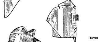
Portable steel booth for placement and transportation of welding station equipment, 2×2 m and 5×2 m in size, with a spotlight
Drawing 5950 PI Promstalkonstruktsiya *
DC welding arc power source
Semiautomatic hose with a set of starting and measuring equipment, control cabinet, platform with reels
Electric welder tool kit
Electric oven for calcination and drying of electrodes
Detachable copper inventory mold, for bathroom welding of vertical joints of fittings
Clamp for fastening half-forms
Flux container
Pliers for carrying hot molds
Container for molds and clamps
* 125080, Moscow, A-80, Volokolamskoe highway, 1
TECHNICAL REQUIREMENTS
1.1.
Requirements for pipeline materials. 1.1.1. For the manufacture of steel process pipelines, it is necessary to use pipes made of materials that comply with the instructions of the customer’s design documentation and, in terms of their chemical composition and mechanical properties, meet the requirements of state standards and technical specifications in accordance with mandatory Appendix 1.
1.1.2. The use of pipes made of other materials is permitted only by agreement with the design organization, provided that the technological and operational characteristics of the replacement materials are not lower than those of the ones being replaced.
1.1.3. The manufacturer must confirm the quality of the pipe material with appropriate certificates.
1.1.4. In the absence of a certificate, the supplier (customer) must, before welding, subject the pipe materials to inspection to confirm compliance of the chemical composition and mechanical properties of the steel grade in accordance with the requirements of the standards or technical specifications given in the mandatory Appendix 1.
1.1.5. Pipe materials that are subject to requirements for resistance to intergranular corrosion, regardless of the availability of a certificate, must be tested for susceptibility to intergranular corrosion in accordance with GOST 6032-75 before being put into production.
1.2. Requirements for welding materials
1.2.1. For manual argon arc welding, the following welding materials must be used:
steel welding wire according to GOST 2246-70;
argon gas according to GOST 10157-73 (highest, first or second grade);
lanthanum tungsten according to TU 48-19-27-77;
tungsten, titrated according to TU 48-19-221-76;
flux paste FP8-2 according to TU 14-4-737-76 and TU 14-4-736-76.
1.2.2. Each batch of welding wire must have a certificate indicating the manufacturer, brand, diameter, heat number and chemical composition of the wire. A tag indicating the manufacturer, heat number and wire designation in accordance with the standard must be attached to each coil (coil) of welding wire.
1.2.3. Each coil of welding wire that does not have a certificate must be checked before welding for compliance with the grade composition by steeloscopy to determine alloying elements. To analyze alloyed and high-alloy welding wire, both ends of the coil are subjected to steeloscopy. In case of unsatisfactory steeloscopy results, a chemical analysis of the wire is carried out. If the chemical composition does not comply with the certificate, this coil of welding wire cannot be used for welding.
1.2.4. Welding wire must be stored in a dry, closed room under conditions that protect it from rust, contamination and mechanical damage in accordance with GOST 2246-70.
1.2.5. The quality of argon in accordance with GOST 10157-73 is certified by the accompanying document, which is placed in the capped valve handwheel of each cylinder.
1.2.6. Before using an argon cylinder, you must check the quality of the gas. To do this, a welding bead 100-150 mm long is fused onto the plate or pipe and the reliability of the gas protection is determined using a technical inspection in accordance with GOST 3242-79 of the weld surface and weld fracture. If there are pores in the weld metal, the gas in this cylinder is rejected.
1.2.7. As non-consumable electrodes for manual argon arc welding, it is necessary to use tungsten rods or wire with a diameter of 0.8 to 4.0 mm in accordance with OST 1.41710-77.
1.2.8. Each batch of non-consumable electrodes must have a certificate from the manufacturer indicating the brand.
1.2.9. The non-consumable electrode must be sharpened into a cone before work. The cone angle (φ) should be equal to 28 - 30°, the length of the conical part (Lz) should be 5-6 electrode diameters (De). The cone after sharpening must be blunted, the diameter of the bluntness (dn) must be equal to 0.2 - 0.5 mm (Fig. 1).
Tungsten electrode sharpening diagram
1.2.10. FP8-2 flux paste should be prepared, transported and stored in accordance with TU 14-4-737-76 and TU 14-4-736-76.
1.3. Requirements for welding equipment
1.3.2. Torches for manual argon arc welding are selected in accordance with mandatory Appendix 3.
1.3.3. To facilitate arc ignition, it is necessary to use oscillators, which are selected in accordance with mandatory Appendix 4.
1.3.4. To reduce the pressure of argon coming from the cylinder to the operating pressure and maintain it constant, it is necessary to use argon reducers with indicating flow meters of the brands AR-10, AR-40 and AP-150 according to TU 26-05-196-74 and an oxygen cylinder reducer DKM -1-70 according to TU 26-05-251-71 with a rotameter of the RS-3 brand, as well as gearboxes of the BKO type according to GOST 6268-78.
1.4. Qualification requirements for welders
1.4.1. Welders of at least 5-6 categories who have passed theoretical and practical tests in accordance with the current “Rules for the Certification of Welders” approved by the USSR State Mining and Technical Supervision on June 22, 1971, and who have a certificate of the established form for the right to perform the relevant welding work are allowed to perform argon arc welding of process pipelines .
Welders who have experience in welding these steels and have passed preliminary tests on welding the corresponding pipes are allowed to weld pipelines made of alloy steels.
1.4.2. Welders who are starting to weld pipelines for the first time during the installation of a given facility or who have had a break in work for more than 2 months, as well as all welders in cases of using new welding materials or equipment, regardless of whether they have test documents, must weld test joints in the presence of master inspector in conditions identical to those in which pipeline welding is carried out.
1.4.3. Test joints must be subjected to technical inspection in accordance with GOST 3242-79, continuity testing using physical control methods and mechanical tests for rupture and bending, and for category I pipelines (SNiP ΙΙΙ-31-78) - also for impact strength.
1.4.4. Welders who fail the test may be allowed to weld pipelines only after passing repeated tests, which are carried out no earlier than 10 days from the date of their removal from welding pipelines.
1.4.5. Each welder must have a personal mark (numeric or letter).
PROCESS TECHNOLOGY AND LABOR ORGANIZATION
4.1. Operations for welding vertical joints of reinforcement of reinforced concrete H-shaped frames are performed in the following order: inspect the joint prepared for welding, install copper forms of two halves on the joining rods and fasten them with clamps; pour flux into the melting space of the molds; charge the semi-automatic hose machine with electrode wire; weld the joints by adjusting the welding mode; remove molds and clean molds and joints from slag; inspect the welded joint and put a mark.
PREPARATION OF SEMI-AUTOMATIC MACHINE FOR WELDING; 20 minutes; E1, E2; welding equipment
Electric welders E1 and E2 roll semi-automatic hose machines to the prepared frame joint and install them on both sides of the conductor at equal distances from the frame joints. Then they fill the semi-automatic machines and flexible hoses with electrode wire, set the semi-automatic machines to the specified welding mode and check their operation
ELECTROSLAG WELDING OF VERTICAL RODS; 25 min; E1, E2, M; welding equipment
The installer turns on the DC generator for driving semi-automatic machines and sets the required voltage using a portable regulator. Electric welders E1 and E2, located at the corners of the column, insert the end of the electrode wire into the melting space of the mold and excite an arc under the flux layer. During the first period, welding is carried out at a voltage of 40 - 45 V, and then, as the joint is filled with weld metal, the installer, using a portable regulator, gradually reduces the voltage to 20 - 25 V in order to avoid undercuts in the upper part of the joined rod. After completing welding of the rods of one vertical joint of the frame, electric welders transfer the hoses to the second joint and weld its rods
REMOVING FORMS; 20 minutes; M; pliers, bucket of water, electric welder tools
20 – 30 minutes after the end of welding (when the molds are cooled to 100 °C), the installer removes the molds. To do this, he unscrews the clamp, lightly taps the rods near the mold with a hammer, separates the mold into two halves, removes them from the rod with pliers and lowers them into a bucket of water. After cooling the molds and joints of the rods, the installer cleans them of slag using a chisel, hammer and steel brush
CONTROL OF WELDING JOINTS OF REINFORCEMENT; 20 minutes; E1, E2; welding equipment, gas cutting machine, set of electric welder tools
Electric welders E1 and E2 inspect the joints, checking the quality of welding and in the presence of defects (undercuts, lack of fusion, weakened weld cross-section, swelling, sharp transition from the deposited metal to the base metal, shrinkage cavities) they weld these places with electrodes using manual electric arc welding. If welding is not sufficient to eliminate defects, electric welders use a gas cutting machine to cut out the defective joint (the total length of the cut section must be at least 150 mm) and join the rods using an insert. Having eliminated all defects, electric welders put marks on their joints and hand them over to the inspection master
Sample technological map for types of welding
For each welding method, there are a number of unique details that are included in the document in order to fully reflect the nuances of the future work.
Manual arc welding with infusible and consumable electrodes
Consumable electrode welding (code 141) is welding in which an electric arc is the source of energy. The welder can work comfortably even in hard-to-reach places. When using non-consumable (coated) consumables (code 111), the output is better welded joints. The advantage of this method is that it becomes possible to alloy ferrous metal with workpieces that differ in structure.
| Name of organization and manufacturing facility | ||
| Welding method | RD 111 | |
| Code NTD, GOST | PB 03-585-03, RD 38.13.004-86, SNiP 3.05.05-84, 16037-80 | |
| Main material (brand) | (M01) steel 20 | |
| Standard size | Diameter - 70 mm, thickness - 5 mm | |
| Seam type | SS (butt weld) | |
| Connection type according to NTD | T (pipe) | |
| Seam position | B1 (vertical) | |
| Type of connection | OS (welded on one side) | |
| Tack Requirements | 3 tacks 10-15 mm long | |
| Materials | Electrode SE 46 GOST 9467-75 | |
| Equipment | Three-phase inverter "FORSAZH-301" | |
| Connection sketches | ||
| Design | Structural elements of prepared edges of parts and seams | Welding order |
| Technological parameters | ||
| Roller (seam) number | I | |
| Electrode or wire diameter | 3 mm | |
| Type and polarity of current | Constant, reverse | |
| Current strength | 80-140 A | |
| Voltage | — | |
| Welding time | 8 minutes | |
| Electrode consumption | 6 items | |
| Quality control requirements | ||
| Control method | NTD code | Control volume (%, number of samples) |
| Visual and measuring | RD 03-606-03 | 100% (1 sample) |
| Radiographic | GOST 23055-78 | 100% (1 sample) |
| Date and signature of the chief engineer |
Gas arc welding
| Name of organization and manufacturing facility | |
| Way | G - gas welding |
| NTD for welding, GOST | PB 12-529-05, SNiP 42-01-2002, SP 42-101-2003, SP 42-102-2004, 16037-80 |
| Main material | Groups - I, II, III, brand - St2sp |
| Method for creating gas protection | Jet |
| Gas type | Inert |
| Electrode type | Non-melting |
| Type of current | Constant |
| Standard size | Diameter - 15-100 mm, thickness - 2-3 mm |
| Type of connection | Butt |
| Type of cutting | Without cutting |
| Connection type | C2 according to GOST 16037-80 |
| Edge preparation form | With bevel >15° |
| Sketches of construction seams and connections | |
| Quality check values | |
| Approval number and specialist signature |
Automatic and semi-automatic using additives or gas
The degree of worker participation in the welding process is the main difference between automatic and semi-automatic equipment. Human functions when working with automation include setting up and monitoring the correct execution of tasks.
Automatic joining of materials can be performed on flux pads. Better results are obtained by using gas ones. They promote the formation of the weld root and, when working with active metals, protect the heated solid material from exposure to air.
The composition of gases supplied to the pad may be similar to those used to protect the welding zone. Gas consumption depends on the composition and thickness of the working surface, joint design, and welding speed. The higher the level of quality of the seam, the more successfully it was possible to push the air away from the welding zone.
| Name of organization and manufacturing facility | |
| Way | Root of the weld: AMA - automatic argon arc welding with a non-consumable electrode. Filling and lining: AADP - automatic welding with a consumable electrode in an environment of inert gases and mixtures |
| NTD for welding, GOST | PB 03-585-03, SNiP 3.05.05-84, 16037-80 |
| Base metal | Group index - carbon steel, grade - 20 |
| Standard size | Diameter - 140 mm, thickness - 20 mm (pipe walls), 23 mm (pipe), 16.5 mm (in the welding zone) |
| Type of connection | Butt |
| Type of cutting | Single-sided, cutting angle - over 15° |
| Connection type | C10 according to GOST 16037-80 |
| Sketches | |
| Quality Control Inspection | |
| Date of drawing up the TC, signature of the responsible person |
Regarding other types of welding work
The route map is developed by specialists for all types of welding work. In this case, additional data is indicated for each individual type according to the specifics of working with it and an unchanged list is entered, which is present in any document:
- a header where the names of the enterprise and object are reflected;
- procedure code;
- base metal parameters;
- type of energy;
- temperature conditions;
- equipment data, etc.
Download document
MAP OF
THE LABOR PROCESS OF CONSTRUCTION PRODUCTION
Developed by the Laboratory of Installation Works at DISI of the Ministry of Montage and Special Construction of the Ukrainian SSR *
Corrected and recommended by the VNIPI of Labor in Construction of the USSR State Construction Committee for implementation in construction production
SEMI-AUTOMATIC WELDING OF JOINTS OF REINFORCED CONCRETE H-FRAME REINFORCEMENT
Included in the set of cards KKT-4.1-0
Installation of reinforced concrete frames of multi-storey buildings
* Dnepropetrovsk-92, st. Chernyshevsky, 24a.
PVC pipe
| PVC pipe 160x3.6x1,000m | PC | 264,37 |
| PVC pipe 160x3.6x2,000m | PC | 503,75 |
| PVC pipe 160x3.6x3,000m | PC | 775,41 |
| PVC pipe 50x3.2x0.500m | PC | 42,30 |
| PVC pipe 50x3.2x1,000m | PC | 70,68 |
| PVC pipe 50x3.2x2,000m | PC _ | 131,85 |
| PVC pipe 110x2.7x1,000m | PC | 104,87 |
| PVC pipe 110x2.7,000m | PC | 195,12 |
| PVC pipe 110x2.7,000m | PC | 298,25 |
PVC pipe
Arc welding is used when connecting galvanized steel heating pipes or pipes made of ferrous metals, and the welding technology can be manual or automatic submerged arc. All types of welding are often used - manual arc, contact, butt.
When connecting parts of the same edge cutting size, it is necessary to comply with all accepted requirements of SNiPIII-42-80. For example, the size of the edge can shift by no more than 80. That is, the displacement of the edges should not exceed 0.15 S + 0.5 mm, where S is the wall thickness.
Manual arc welding is most often used for welding water pipes. Also, for this purpose, automatic or semi-automatic welding technology can be used; the initial workpiece will be hot-rolled sheet steel with a measured length. Recently, powder welding, butt welding with high-frequency heating, is often used.
Arc welding is used for joining profile stainless steel. How is arc welding for a profile pipe divided: with a profile pipe thickness of 0.8 mm, joint welding with a short arc is used, from 0.8 to 3 mm - conventional arc welding, more than 3 mm - arc welding with electrodes melting in an inert gas. For a profile pipe, a current value of 40-60 A is suitable. Welding of the root of the seam of the profile pipe is required, but the metal itself in the joint area should not be burned. That is, manual wiring of the electrode is required without tearing it off along the pipe.
When welding, during heating of a profile pipe of large or small cross-section, heat spreads in depth, the pressure on the pieces being welded is almost zero. After this, the heater should be removed in such a way that damage or contamination of the heated joint surfaces does not occur.
The contact surfaces must be connected, avoiding a long time interval between removing the electrode and connecting, otherwise the heated surface will harden, which will negatively affect the quality of the seams. During this time, the final grant and bonds between molecules are formed, which will ensure the uniformity of the pipe joint seam. Next comes cooling.
Features and types of welding steel pipes
Welding is an extremely popular type of work with heating pipes, water supply pipes and any other purpose. Different types are used for welding steel
We work around the clock
+7 — DESIGN PRESTIGE LLC
+7 Holding SpetsStroyAlliance
CONDITIONS AND PREPARATION FOR THE PROCESS
2.1. Before starting work, it is necessary to: install and secure the frame on the conductor in the design position; carry out a geodetic check of the position of the frame; prepare the joining rods for welding.
Note: The jig may only be removed after all joining rods have been welded.
2.2. Before use, the flux must be calcined for an hour at a temperature of 200 - 300? C.
2.3. Work should be carried out in strict compliance with the safety and labor protection rules for workers in accordance with SNiP III-A.11-70, § 5.
Features of the welding process
Before assembling the pipes, they are first cleaned by removing dirt, soil and snow from the internal area. After this, the parts of the pipe adjacent to the edges with the edges themselves, as well as the parts for the connection, are cleaned until the metal shines (more than 1 cm). The same distance from the joint is required by the rules of pipeline welding to grind the section of reinforcement of its external seam, made at the factory, adjacent to the connected end of the pipe.
Typically, factory pipes are supplied with edges already cut for manual arc welding. However, for pipelines of significant diameters, special cutting is required to perform an internal weld.
When assembling pipes, it is necessary to strictly observe the perpendicularity of the pipeline axes with joints with a deviation of no more than 2 mm. In this case, the gap must be uniform throughout the entire perimeter of the connection, and possible displacements of the edges and longitudinals of factory seams must comply with the permissible values established for welding high-pressure pipelines or distribution lines. If it is not possible to comply with standard values, additional monitoring of the resulting connection at the joint using ultrasound is necessary.
PERFORMERS, OBJECTS AND TOOLS OF LABOR
electric welder of the V category (E1) – 1
electric welder of IV category (E2) – 1
construction installer II category (M) – 1
3.2. Tools, devices and equipment
Name, purpose and main parameters
Portable steel booth for placement and transportation of welding station equipment, 2×2 m and 5×2 m in size, with a spotlight
Drawing 5950 PI Promstalkonstruktsiya *
DC welding arc power source
Semiautomatic hose with a set of starting and measuring equipment, control cabinet, platform with reels
Electric welder tool kit
Electric oven for calcination and drying of electrodes
Detachable copper inventory mold, for bathroom welding of vertical joints of fittings
Clamp for fastening half-forms
Flux container
Pliers for carrying hot molds
Container for molds and clamps
* 125080, Moscow, A-80, Volokolamskoe highway, 1