• The ends of the cellular polycarbonate are treated with vapor-permeable tape.
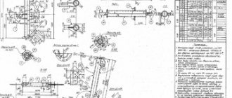
Drawings of metal structures are combined into a set of drawings of the KM brand - metal structures. The drawings of this brand include: General data - title page; Drawings of views, plans, sections; Layout diagrams of structural elements; General data on metal structures include various statements and specifications necessary for completing documents and products, as well as installation of metal structures. Layout diagrams of structural elements are made on a scale of 1:100, 1:200, 1:400. The diagrams show the location of individual structural elements and indicate their brands. If the dimensions of the longitudinal structural elements significantly exceed the dimensions of the transverse elements, then the latter are drawn on a larger scale. Working drawings of the KM brand must contain complete data for the development of detailed KMD drawings, drawing up estimates and ordering metal. KMD drawings are developed, as a rule, in the design departments of factories metal structures and contain all the necessary data for the manufacture and installation of structures. Drawings of metal structures are made in accordance with the requirements of GOST 2.410-68 ESKD standards “General rules for the execution of drawings”, as well as the State Standard of the Republic of Belarus “Metal structures. Rules for the execution of drawings of the KM brand." And GOST 21.101-93 “Basic requirements for working drawings”. One of the features of drawing drawings of metal building products (structural elements) is the system of arrangement of views: top view in projection connection above the main view; bottom view - under the main view; right view - right from the main view; view to the left - to the left of the main view. In this case, each view (except the main one) must be marked on the drawing with a capital letter. The direction of view is indicated by an arrow marked with the corresponding letter (Fig. 5.1). Fig. 5.1. Location of views on construction drawings Drawings of metal structures, views and sections depict all visible parts of structures and their connections, located on the face closest in the direction of view. Of the invisible parts, only those that are located close to the visible ones are shown (Fig. 5.1). If necessary, its geometric diagram is drawn with solid main lines on the drawing of the metal structure (Fig. 5.2).
Rice. 5.2. Geometric diagram of a truss For symmetrical structures, draw a diagram of half of the structure. The dimensions of the distances between the intersection points of the axial lines of the rods are plotted above the diagram lines without extension and dimension lines (Fig. 5.3).
Rice. 5.3. Geometric diagram of half of the structure In addition to the dimensions, if necessary, the geometric diagram is marked with calculated forces with the corresponding signs. If the simultaneous application of dimensions and forces in diagrams of symmetrical structures makes it difficult to read the diagram, then it is drawn out completely, with the dimensions applied on one half of the diagram and the forces - on the other (Fig. 5.4).
Rice. 5.4. Geometric design of the structureChoosing the outline of the trusses is the first stage of their design. The outline of the trusses depends on the purpose of the arms, the type of roof, the type of connection of the trusses with the columns (hinged or rigid) and other features of the design situation. The outlines of some types of trusses are shown in Fig. 5.5.
Rice. 5.5. Outlines of trusses: a) trapezoidal; b) polygonal; c) triangular; d) with parallel chords. Individual elements of metal structures are connected to each other by welding, rivets or bolts. Conventional images and designations of seams of welded joints are carried out in accordance with GOST 2.312-72. ESKD. This GOST is used when making mechanical engineering drawings, drawings of the KZh brand. On the drawings of building metal structures, conventional images of seams of welded joints are used in accordance with GOST 21.504-2005 “System of design documentation for construction. Metal structures. Rules for the execution of drawings of the KM brand", which was introduced in connection with the abolition of SN 460-74 on the territory of the Republic of Belarus (Table 5.1). In accordance with this GOST, seam designations are placed directly above or below the image of the corresponding weld, regardless of whether the seam is visible or invisible (Fig. 5.6).
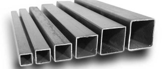
For example, the inscription 6-80 above the image means: the seam has a length of 80 mm with a leg of 6 mm. Metal structures are used in all types of buildings and engineering structures. Fig. 5.6. Designation and sizing of welds The required materials for all structures are: rolled steel (angular, I-beam, channel), sheet steel, steel pipes. In Fig. Figure 5.7 shows the most common rolled steel profiles.
Rice. 5.7. Rolled steel profiles: a) equal angle; b) unequal angle; c) T-profile; d) I-beam; e) channel; e) zeta profileElements determined by b
and
h
are called the flange and wall of the profile, respectively.
In Fig. 5.8 gives the names of the elements of the corner profile, Z 0
is the distance from the butt to the center of gravity of the corner.
Rice. 5.8 Elements of a corner profile A metal truss is made of steel profiles; a corner is most often used for this. If a heavier structure is to be installed, the profile should have a T-section or I-beam section. For hydraulic structures, a round cross-section is used, as well as a profile pipe. Metal truss trusses are widely used in structures for roofing buildings, most often the span width exceeds 24 meters.
Several forces act on the frame at once; it is necessary to accurately determine the equilibrium points so that the structure can withstand even high loads.
Technological process
1. Preparing metal for welding: low-alloy steels are cut into blanks by gas, plasma or air-arc cutting, followed by cleaning of heating areas with cutting or abrasive tools until traces of fire cutting are removed.
Before assembling the joint, welded edges up to a width of 20 mm are cleaned to a metallic shine and degreased. The joints are assembled using assembly jigs or using tacks. They are installed using filler wires of the same brand that will be used for welding. The tack height is equal to 0.6 - 0.7 of the thickness of the parts being welded, but not less than 3 mm, with a wall thickness of up to 10 mm, or 5-8 mm with a wall thickness of more than 10 mm. Tack welding must be done with full penetration. Their surface must be thoroughly cleaned. Tacks with unacceptable defects should be removed mechanically. The welding wire is calcined for 1.2 - 2 hours at a temperature of 150 - 250? C. Rust on the wire dramatically reduces the stability of the welding process. It is recommended to remove rust by etching the wire in a 5% solution of hydrochloric acid, followed by calcination for 1.5 - 2 hours at a temperature of 150 - 250? C.
2. The technological process of welding a metal truss begins with the manufacture of its elements - corners, channels, gussets, etc. according to specified drawings. The manufactured truss elements are assembled on a rack or in stocks and fastened with short welds. The sequence of applying welds when welding a tack-assembled truss must be carried out in accordance with a technology that provides for obtaining minimal warpage that is permissible without subsequent straightening of the truss - the order of welding of units should always be from the middle of the truss to its ends.
1. On the racks, using clamps, limiters and fastening devices, lay out the first branches of the upper and lower chords of the truss according to the drawing.
2. At the nodal points of the belts, scarves are installed, pressed with clamps or brackets to the branches of the belts and grabbed.
3. Check the correct position of the belts and nodal points, measuring with a ruler or string in the direction of the posts, braces and connections their theoretical length between mutually opposite points and at the same time marking marks on the gussets in the direction of the lattice elements.
4. Lay out the first branches of the racks and braces, maintaining the minus value at each node and, guided by the coincidence of the marks on the gussets and at the ends of the lattice rods, press the rods to the gussets and place tacks.
5. Turn the assembled branch of the truss 180°, lay out the gaskets on the belts and lattice elements according to the drawing, press them and grab them.
6. Lay out the second branches of the belts, racks, braces and ties, guided by the first branch of each element, press them and grab them to the gussets and spacers.
7. The assembled truss is welded. Welding of the nodes begins from the middle of the truss and proceeds symmetrically to its ends. In each unit, first the gussets are welded to the belts, and then the posts and braces are welded to the gussets.
8. Turn the truss 180° a second time and weld the nodes on the side of the first branches of the chords, racks and braces in the same order.
9. After welding all the seams, the truss undergoes final operations, after which it enters the finished product warehouse.
Why is it better from a profile?
Welding trusses from profile pipes has a number of advantages over other materials:
- such structures are fire-resistant and do not require special treatment with fire-resistant impregnations;
- the frame is able to withstand the loads of its own weight, as well as from wind or snow pressure;
- the pipe bends well in fixtures, which allows you to create a variety of shapes and design solutions;
- To prevent corrosion, it is enough to paint the material;
- the profile is easy to buy in any region of the country;
- if an erroneous cut was made during installation, the beam can be restored by welding (which will not work on wooden beams);
- the profile is relatively light due to its hollow structure;
- the frame does not deform over time and can serve for a very long time.
Features of the technology for manufacturing lattice structures - trusses
What is common to lattice structures is the presence of several separate rods of one or another section at the joints.
Trusses, like beams, work in transverse bending. The structural forms of beams are simpler, however, with sufficiently large spans, the use of trusses turns out to be more economical. Typical truss lattice designs are shown in Fig. 39. Triangular (a) and diagonal (b) patterns are the main ones. Trusses that take loads along the upper or lower chord, in order to reduce the length of the panel, are manufactured according to the diagrams shown in Fig. 39, c, d. Sometimes they use trusses without braces with rigid nodes (Fig. 39, e). According to the outline of the belts, trusses can have parallel belts or belts formed by a broken line (Fig. 39, e). According to their purpose, trusses are divided into trusses and bridges.
Rafter trusses operate under static load. Rolled and, less commonly, bent closed welded profiles and pipes are used as rods. In the total production volume, trusses made from paired rolled angles account for about 90%. The rods in the nodes are connected either directly or with the help of auxiliary elements by arc welding. The use of spot resistance welding is promising. Due to the static nature of the loading of trusses, the sensitivity to stress concentration in point connections is low; at the same time, resistance welding provides a significant increase in the productivity of assembly and welding work.
Bridge trusses operate under variable loads and often at low climatic temperatures, which determines the high sensitivity of their welded joints to stress concentrations. Therefore, in the process of designing and manufacturing welded bridge spans, special attention is paid to preventing and eliminating stress concentration in welded joints and assemblies.
Lattice spans with a ride underneath are used for railway bridges. For road bridges, it is more typical to use steel and steel-reinforced concrete solid-wall span structures with a ride on top.
Due to their high height, tower-type spatial lattice structures (for example, radio masts, radio towers, drilling rigs) are subject to significant wind loads, so they are made mainly from tubular elements. Since the dimensions of these structures exceed the dimensions of railway rolling stock, they are assembled from sections welded at the factory. The main pillars of the tower are located at the corners of the sections' faces and are the belts of flat trusses. The racks are made up of separate pipes of standard length and are connected to each other with bolts through flanges welded to their ends.
Drilling rigs for oil and gas production in the open sea operate in particularly difficult conditions at depths of about 150,200 m. In addition to wind, they experience significant loads from wave impacts. Therefore, large diameter pipes are used in these structures. Thus, the supports of drilling rigs for oil production in the North Sea at depths of more than 150 m are constructed from pipes with a diameter of up to 4270 mm and a wall thickness of up to 64 mm.
Advantages of profile pipes
The choice of a rectangular profile for the construction of a canopy is recommended by experts, as it has the following advantages:
- does not require treatment with fire-resistant compounds,
- the profile bends easily without deformation using simple devices, which allows you to create complex shapes,
- protection against corrosion is carried out by simple painting,
- Availability of purchase in all regions,
- an error during cutting is corrected by welding the section to its original place,
- low weight compared to other rolled metal of equal strength,
- long service life.
Factors affecting the calculation
Before starting work, you will need to determine the size and height of the structure. This work is carried out in several stages.
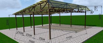
First you need to decide on the covering material. Polycarbonate canopies are most in demand due to their lightness and strength. The number of trusses and the installation pitch of the racks depend on the choice of material. For a small canopy, making trusses is not required.
Before welding and other work, it is necessary to make a sketch of a canopy made of profile pipes, on which the size and type of trusses and the dimensions of parts are determined. It is better to make a separate specialization, with profile sizes and part lengths.
When cutting, such a scheme will help you avoid mistakes and save material. Drawings or a sketch of the canopy can be done on a laptop using a special program or drawn by hand.
Exact dimensions can only be obtained at the site of installation and manufacture of the canopy. In this case, it is necessary to take into account the method of installation and fastening of all stand-up parts.
If the canopy is adjacent to the wall on one side, you can make embedded parts and secure them in the places where the trusses are installed.
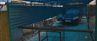
Performing installation
To carry out the installation, you will need to fasten trimmed corners with 30 mm shelves to the wall of the house every 1500 mm from the outer truss with 3-4 self-tapping screws.
There will be 5 such attachment points, depending on the number of trusses. On the contrary, at a distance of 3060 mm from the wall, holes are dug or drilled for racks from a profile pipe with a shelf width of 80 or 100 mm.
Five pieces with a length of 2900 mm are cut. A piece of sheet metal must be welded to the upper end of the profile pipe. This will prevent water and snow from getting inside and will ensure reliable welding of the rack and truss. They are installed in the holes and buried 800 mm.
From the level of the main finished floor, the height of the canopy posts should be 2100 mm for a passenger car. The stands must be installed strictly in a vertical position and secured with the help of jibs. Then fill the holes in the ground with concrete. Now you can take a break for a day to allow the concrete to completely harden.
Requirements depending on the angle of inclination
All metal trusses used for the construction of roofs are divided into three categories:
- with slope angle from 6 to 15°;
- from 15 to 22°;
- from 22 to 33°.
It is believed that it is advisable to install roofs of the first type using trapezoidal trusses with a height of 1/7 to 1/9 of the span. If the construction does not intend to hem the ceiling in the future, the braces in such a structure are installed in the form of a triangular lattice.
To assemble roofs with a slope angle from 15 to 22°, trusses with a height of 1/7 of the span are usually used. This allows you to mount the most reliable structure. If a greater height is required (0.16-0.23 parts of the span length), the lower chord is made broken. Using this method, the weight of the frame can be reduced by 30%.
Installing trusses from steel angles with a broken bottom chord is allowed only on structures with a span length of no more than 20 m. Otherwise, it is necessary to install Polonso structures.
For trusses with a slope angle of 22-30°, a height of 1/5 of the span length is usually chosen. In this case, the structure will be optimally light and rain and snow will quickly drain from it. Triangular trusses made from corners are usually mounted on such buildings.
Roofs with such slope angles are covered in most cases with slate or metal sheets. For long spans from 14 m, trusses with downward braces are most often used. Such structures can withstand significant snow and wind loads well.
What are Polonso Farms?
Such structures consist of two triangular parts connected by a screed. The main advantage of such trusses is that there is no need to use long braces. Thanks to this, the design is not only durable, but also lightweight.
Such trusses, as already mentioned, are installed for long spans. Most often they are used in the construction of large industrial buildings.
How to create a project
Before starting to independently assemble a truss from paired angles, single angles or pipes, you should decide:
- with roof configuration;
- slope angle.
The number of metal truss slopes may vary. Using such structures, it is also possible to build multi-gable complex roofs. However, in private farms, most often when constructing small architectural forms, single- or double-slope trusses are installed. Such designs are easy to assemble and at the same time reliable.
The angle of inclination of roof slopes with a metal truss is determined depending on wind and snow loads and some other factors. It is difficult to independently calculate this parameter for steel rafter systems according to all the rules, unlike wooden ones, without special knowledge. Therefore, in most cases, owners of suburban areas simply find a standard formula for a farm of one design or another. Next, the necessary indicators are substituted into it.
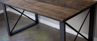
Shape selection
In order to properly weld trusses from a profile pipe as quickly as possible, you need to decide on its shape. It depends on the type of future construction. For a canopy, a beam truss is suitable, in which the belts are located parallel, or the roof has a pitched slope. Arched trusses look more beautiful. The profile is bent using a pipe bender, and the ceiling is made of polycarbonate, which easily follows the shape of the roof.
If you need to create a huge canopy for a large number of cars, then a shed structure is suitable. And for a gazebo or pool, a portal or double-hinged truss will look more elegant. Such hipped or gable options add nobility to this simple structure and add variety to the surrounding buildings.
Important points
Before starting work, you need to decide on the dimensions of the structure, profile and the required amount of material. Welding of a canopy made of profile pipes is carried out using a manual arc apparatus. Be sure to wear protective clothing and a mask.
You should not rush when welding; you must ensure reliable penetration of the metal. It is better to use MP-3 or ANO-21 electrodes. It is necessary to correctly position the parts when joining and welding the structure.
When the canopy is used and rust forms on it, the damaged area is cleaned with sandpaper and painted with primer. In case of heavy snowfalls, snow is removed from the roof of the canopy.
Source of the article: https://svaring.com/welding/v-bytu/kak-svarit-naves-iz-profilnoj-truby
Frame assembly
At the next stage, the trusses prepared in this way are lifted onto the racks or box of the building. The upper frame of the structure and support beams are pre-assembled from a corner or pipe. The trusses are welded and then connected to each other with a ridge element and intermediate jumpers. The latter are usually mounted at a distance of at least 1.5 m from each other.
At the final stage, all truss structures made from a metal angle or pipe are sanded, coated with a primer and painted. After this, they begin to actually sheath the roof.