Figure 1 - Main types of welded joints: a - butt;
b - tee; c - angular; d - lap welds Welds are divided according to the cross-sectional shape into butt (Figure 2.a) and corner (Figure 2.b). A variation of these types are cork seams (Figure 2.c) and slotted seams (Figure 2.d), made in overlap joints. Based on their shape in the longitudinal direction, continuous and intermittent seams are distinguished.
With the help of butt welds, mainly butt joints are formed (Figure 1.a), with the help of fillet welds - T-, cross, corner and lap joints (Figure 1.b - 1.e), with the help of plug and slotted seams lap joints can be formed and sometimes T-joints.
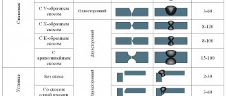
Butt welds are usually made continuous; A distinctive feature for them is usually the shape of the cutting of the edges of the parts being connected in cross section. Based on this feature, the following main types of butt welds are distinguished: with flanged edges (Figure 3.a); without cutting edges - one-sided and two-sided (Figure 3.b); with cutting of one edge - one-sided, two-sided; with a straight or curved cutting shape (Figure 3.c); with one-sided cutting of two edges; with a V-shaped groove (Figure 3.d); with two-sided cutting of two edges; X-shaped cutting (Figure 3.d). The groove can be formed by straight lines (beveled edges) or have a curved shape (U-shaped groove, Figure 3.e).
Figure 2 - Main types of welds: a - butt; b - angular; c - cork; g - slotted
The butt connection is most common in welded structures, as it has a number of advantages over other types of connections. It is used in a wide range of thicknesses of welded parts from tenths of a millimeter to hundreds of millimeters in almost all welding methods. With a butt joint, less filler material is consumed to form a seam, and quality control is easy and convenient.
Fillet welds are distinguished by the shape of the preparation of the welded edges in cross section and the continuity of the seam along the length.
According to the cross-sectional shape, fillet welds can be without edge grooves (Figure 4.a), with one-sided edge grooves (Figure 4.b), with double-sided edge grooves (Figure 4.c). In terms of length, fillet welds can be continuous (Figure 5.a) or intermittent (Figure 5.b), with a staggered (Figure 5.c) and chain (Figure 5.d) arrangement of seam sections. T-joints, lap joints and corner joints can be made with short sections of seams - spot welds (Figure 5.e).
Figure 4 - Preparation of the edges of fillet welds of T-joints: a - with flanging of the edges; b - without cutting edges; c, d, e, f - with edge grooves
Figure 4 - Preparation of the edges of fillet welds of T-joints: a - without cutting the edges; b, c - with edge cutting
Plug seams in their plan form (top view) usually have a round shape and are obtained as a result of complete melting of the top and partial penetration of the bottom sheets (Figure 6.a) - they are often called electric rivets - or by melting the top sheet through what was previously done in the top sheet hole (Figure 6.b).
Figure 5 - Fillet welds of T-joints
Figure 6 — Cross-sectional shape of plug and slotted seams
Slotted seams, usually of an elongated shape, are obtained by welding the top (covering) sheet to the bottom with a fillet weld around the perimeter of the slot (Figure 6. c). In some cases, the slot may be filled completely.
The shape of the edges and their assembly for welding are characterized by four main structural elements (Figure 7): gap b, blunting c, bevel angle b and cutting angle a, equal to b or 2b.
Existing methods of arc welding without cutting edges make it possible to weld metal of limited thickness (for one-sided manual welding - up to 4 mm, mechanized submerged arc welding - up to 18 mm). Therefore, when welding thick metal, it is necessary to cut the edges. The bevel angle of the edge provides a certain value for the cutting angle of the edges, which is necessary for the arc to penetrate deep into the joint and completely penetrate the edges to their entire thickness.
Figure 7 — Structural elements of edge preparation and assembly for welding
The standard cutting angle of the edges, depending on the welding method and type of connection, varies from (60±5) to (20±5) degrees. The type of groove and the angle of the edges determine the amount of additional metal required to fill the groove, and therefore the welding performance. For example, X-shaped cutting of edges compared to V-shaped allows reducing the volume of deposited metal by 1.6 - 1.7 times. The time required for edge processing is reduced. However, in this case it becomes necessary to weld on one side of the seam in an awkward ceiling position or to turn over the products being welded.
Bluntness c is usually (2 ± 1) mm. Its purpose is to ensure proper formation and prevent burns at the top of the seam. The gap b is usually equal to 1.5 - 2 mm, since at the accepted cutting angles the presence of a gap is necessary for penetration of the top of the seam, but in some cases, with a particular technology, the gap can be equal to zero or reach 8 - 10 mm or more.
For all types of seams, complete penetration of the edges of the elements being connected and the external shape of the seam, both on the front side (strengthening the seam) and on the back side, i.e. the shape of the reverse bead, are important. In butt welds and especially one-sided welds, it is difficult to weld the blunting edges to their entire thickness without special techniques to prevent burn-through and ensure good formation of the return bead.
Welds are classified according to a number of characteristics. Based on their appearance, seams are divided into convex, normal, and concave (Figure 8). As a rule, all seams are made with slight reinforcement (convex). If joints without reinforcement are required, this should be indicated on the drawing. Fillet welds are made weakened (concave), which is also noted in the drawing. Such seams are required to improve the performance of welded joints, for example under variable loads. Butt seams are not weakened; concavity in this case is a defect. An increase in the size of the welds compared to the specified ones leads to an increase in the weight of the welded structure and excessive consumption of electrodes. As a result, the cost of welded structures increases and the labor intensity of welding work increases.
Figure 8 - Classification of seams by appearance: a - convex; b - normal; c - concave
The formation of a smooth transition of the metal of the front and back rollers to the base metal is also of great importance, as this ensures high strength of the connection under dynamic loads. In fillet welds, it can also be difficult to weld the root of the seam to its full thickness, especially when welding with an inclined electrode. For these seams, a concave cross-sectional shape of the seam with a smooth transition to the base metal is recommended, which reduces the stress concentration at the transition site and increases the strength of the connection under dynamic loads.
Based on the number of layers and passes, single-layer, multi-layer, single-pass, and multi-pass seams are distinguished (Figures 9, 10).
Figure 9 - Classification of seams according to execution: a - one-sided; b - bilateral
Figure 10 - Classification of seams by the number of layers and passes: I - IV - number of layers; 1 - 8 - number of passes
Weld layer - part of the weld metal, which consists of one or more beads located at the same level of the cross-section of the weld. Bead - weld metal deposited or remelted in one pass.
When welding, each layer of a multilayer seam is annealed when the next layer is applied. As a result of this thermal effect on the weld metal, its structure and mechanical properties are improved. The thickness of each layer in multilayer seams is approximately 5 - 6 mm.
According to the effective force, seams are divided into longitudinal (flank), transverse (frontal), combined, and oblique (Figure 11). The front seam is located perpendicular to the force P, the flank seam is parallel, and the oblique seam is at an angle.
Figure 11 - Classification of seams according to the effective force: a - longitudinal (flank); b - transverse (frontal); c - combined; g - oblique
Based on their position in space, there are lower, horizontal, vertical and ceiling seams (Figure 12). They differ from each other in the angles at which the surface of the welded part is located relative to the horizontal. The ceiling seam is the most difficult to perform; the seam is best formed in the lower position. Ceiling, vertical and horizontal seams usually have to be made during manufacturing and especially during installation of large-sized structures.
Examples of designating welds by their position in space are given in Figure 13.
Figure 12 — Classification of welds according to their position in space
Figure 13 - Designation of welds according to their position in space: H - lower; P - ceiling; Pp - semi-ceiling; G - horizontal; Pv - semi-vertical; B - vertical; L - in a boat; PG - semi-horizontal
Classification of welds
There are numerous types and types of welds and welds. This created a need for their clear classification. It is designed depending on many factors. The classification takes into account the technological features of the seams, their spatial position, and dimensions. The advantage of this differentiation is the use of designations for each type of weld.
There are many different positions for which there is a classification, including existing types of welding and types of welded joints.
Seam position in space
The location of the seam in space plays an important role.
The bottom position is the most advantageous. The seam is thus strong and reliable. In the upper position, which is otherwise called the ceiling position, the welder has to take an unnatural position. It is very difficult to maintain it for a long time. But one of the conditions for obtaining a high-quality seam is the continuity of the process.
To increase accuracy, a short arc should be used, and the width of the seam should not exceed the diameter of the electrode. To perform a ceiling seam, it is necessary not only to obtain a specialized education, but also to acquire practical skills under more favorable conditions.
When making seams in all positions, there is a problem of molten metal flowing down. The bottom position is the most advantageous. The ceiling and bottom positions are considered horizontal. Excessive metal dripping is reduced by lowering the heating temperature. This can be done by increasing the speed of movement of the electrode, or regularly interrupting the arc, allowing the metal to cool.
A vertical seam is often found in designs, but it is not the simplest option. If the seam is located vertically, then not the entire weld pool will rush down, but only individual droplets. If welding is carried out from top to bottom, then these droplets will begin to quickly solidify, forming a kind of barrier. Therefore, welding with the vertical method should be carried out from the bottom up. The parts to be welded must be securely fixed in a vertical position.
Seam length
Welding seams and connections are divided according to their length. According to this feature, the seam can be continuous or intermittent. When making an intermittent seam, certain intervals are provided in it, having a constant size. Intermittent welds come in a variety of types. They, just like continuous ones, can be one-sided or two-sided.
This gradation is reflected in the seam designation in the drawings. In this case, such a concept as seam pitch is introduced.
Surface shape
Types of welds are divided according to the shape of their outer surface.
Each type has its own advantages. It plays a role in how much load the weld can withstand. When static loads are expected, it is advisable to use a convex seam. It has several layers, which leads to additional consumption of electrodes and increased cost of the welding process.
If you have to weld thin metal sheets, it is better to use a concave shape. If the welded product will be subject to dynamic loads during operation, then flat or concave seams should be made. This choice is explained by the fact that there will not be a large difference between the surfaces of the seam and the base material.
Depending on the operating conditions, the types of welds are divided into working and non-working. Workers have to withstand significant loads, which makes increased demands placed on them. Non-working ones simply perform the connection function. However, if they are intended to be used in less than favorable weather conditions, then careful monitoring of the absence of cracks and internal voids is necessary.
When you have to weld thin metal sheets, it is better to do it with a thread seam. For the surfacing method, the widened version is more suitable.
Number of layers
The types of seams in welding depend on the number of layers performed. Single-layer seams are performed in one pass, while multi-layer seams are multi-pass. The multilayer version is used for connections that have a specific configuration.
Making a multi-pass seam is more difficult. Each new layer should be applied quickly before the previous one has cooled down. In addition, you need to have time to remove the slag that formed earlier. The mechanical characteristics of a multilayer seam have a positive effect because when a subsequent seam is applied, annealing occurs in the previous one.
Shape and extent
The shape of the seam can be convex, even (flat). Sometimes it becomes necessary to make a concave shape. Convex joints are designed for increased load.
The concave areas of the alloys withstand dynamic loads well. Flat seams, which are made most often, are characterized by versatility.
The length of the seams is continuous, without intervals between the fused joints. Sometimes interrupted stitches are sufficient.
An interesting industrial variation of the intermittent seam is the joint formed by resistance seam welding. It is done on special equipment equipped with rotating disk electrodes.
They are often called rollers, and this type of welding is called roller welding. Continuous connections can also be made using such equipment. The resulting seam is very strong and absolutely airtight. The method is used on an industrial scale for the manufacture of pipes, containers, and sealed modules.
Connections
Welded joints are divided into various types.
Types of welded joints:
- Butt . The parts are located in the same plane.
- Angular _ The parts to be connected are placed at the required angle. The most common is the right angle.
- T-bars . The end of one part is placed perpendicularly or at a slight angle relative to the main surface of the second part.
- Overlapping . The position of the parts in space is parallel. In this case, one part partially overlaps another.
- End . The two ends of the elements are welded together.
The butt weld is used for welding pipelines, various pipes and metal sheets. The end surfaces are subject to welding. Butt welding requires preparatory work, which consists of carefully adjusting the end surfaces to each other. To ensure accuracy, a preliminary weld can be used. Butt welding can be carried out either suspended or on a backing - steel or copper. For butt joints, various types of edge bevels or welding without them are possible.
The advantages of this method include reduced consumption of auxiliary material, in particular electrodes. Equal thickness of elements is not a requirement. But in this case, the electrode should be directed to a thicker part. This will ensure stronger heating and protect the thin part from burns.
Fillet welds are used to connect parts of various containers and tanks. To obtain a high-quality corner connection, it is recommended to install the parts in a “boat” manner.
T-welds are used when welding load-bearing structures. The surfaces of the parts require careful preparation. This type of welding is one of the most durable. The advantage of a T-joint is that it can be used in hard-to-reach places. This type of weld helps to withstand increased loads.
The overlap connection is used when it is necessary to weld metal sheets with a thickness of no more than 12 mm. A necessity is the absence of gaps between the surfaces of the parts. A tight fit is necessary for a quality connection. Making an overlap connection is not difficult and can be carried out by welders with a low level.
With the overlap method, the two seams are spaced apart. This gives the connection additional strength. If fracture loads are possible during operation, then it should not be used. End types of welding joints involve welding the ends of parts. In this way it is possible to connect parts of any thickness. The advantage is minimal deformation of the elements being welded.
general characteristics
Butt joints for steels and metal alloys, as well as plastics, are extremely popular.
The process is characterized by productivity and ease of mechanization, and the result is strength and tightness, so the technology is used:
- in serial production and for one-time repair operations;
- in enterprises and in the construction sector;
- in various sectors of the economy - transport, mechanical engineering, mining enterprises, etc.
Electrode position during the welding process
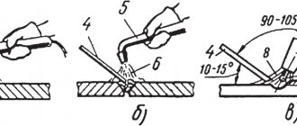
The inclination of the electrode depends on the types of welded joints and seams. The angle of inclination affects the rate of heating of the metal. When arc welding, in order for the arc to light, the electrode must be held perpendicular. Then you need to perform a slight tilt. The welding seam will be of better quality if welding is carried out with a short arc.
It makes sense to use the “forward angle” welding method when the process is carried out in hard-to-reach places. However, the method is not without drawbacks. The welding process will be interfered with by liquid slag, which is always in front. The welding arc may either go out completely or begin to “wander.” The quality of the seam can be significantly reduced if missing areas appear.
The “back angle” method is used in the corner version and when connecting joints. When welding at right angles, the electrode is held perpendicular to the surface. This allows you to control the liquid slag and ensure that it follows the weld pool. This will have a beneficial effect on the quality of the seam. If the slag ends up in front of the electrode, this can be corrected by switching to the “back corner” method for a while.
Electrode movements
The types of welds and methods of their application, in particular, depend on the way in which the electrode moves. The trajectory of its movement can be chosen by the welder himself, depending on the thickness of the elements and types of welded joints.
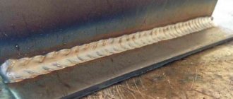
If the electrode moves along the seam, a thin bead is obtained. Such a thread-like seam can be used as the first layer in a multi-pass method.
When the electrode vibrates transversely, the connection becomes stronger. Oscillatory movements provide good heating of the root of the seam and its edges. The amplitude of oscillation allows you to obtain a seam of a given size. The nature of the electrode movement in this case is reciprocating. The end of the electrode can describe different shapes - “stairs”, “triangles”, “herringbones”, “crescent”, “loop”.
The choice depends on the types of welding joints. For example, for butt and fillet welds, a “crescent” would be appropriate, and a “loop” would provide a connection between thin sheets of metal.
How is a joint indicated in the drawings?
The Unified System of Design Documentation (ESKD) clearly defines the designation of welds.
Butt welding is also indicated. The symbol then takes the following form:
- remote shelf with one-way arrow;
- seam type according to the standard used;
- seam width information.
Preparation for welding
An important factor that determines the properties of a welded joint is preparatory actions. They include several stages.
Edit
It is a restoration operation and is carried out when parts are deformed during transportation to the welding site. It is also necessary to return parts of the product to their original shape if, during storage, distortions in the form of dents, bulging, waviness, warping of the surface, and various types of curvature have occurred.
It can be carried out by heating or cold, which depends on the complexity of the resulting defect and its size. Editing can be done either manually or by machine in industrial production.
For manual straightening, tools such as a hammer, sledgehammer or hand press are used. If the damage is more serious, then presses equipped with electric motors can be used. Convenient to use an anvil. Steel or cast iron plates are also suitable.
The straightening hammer is made of soft material. Depending on the defect, a rubber one may be suitable. You should not use a hammer whose head is square in shape, as this may leave dents in the metal. A round shape is preferred. You should check that the surface of the striker is polished. If the metal is hardened, then a straightened hammer must be used. Alternatively, you can use a wooden or metal trowel.
Different defects are corrected in different ways. Waviness and convexity can be corrected by striking the surface. In this case, you need to move from the edges to the central part. When approaching the center, the frequency of blows increases, but their strength decreases. Fine details are corrected with smoothing bars.
Marking
The dimensions of the part must be in accordance with those indicated in the drawings on them. To be able to trim off excess pieces, the required dimensions can be set using markings.
Markings can be applied with a pencil, pen, chalk, thin felt-tip pen, or any sharp object. The tools you will need are a ruler or tape measure, a caliper, and a square. When a batch of similar parts is produced, a template can be used. In addition to the contours of the part, you can use markings to mark the expected bend locations.
cutting
The workpieces are cut to obtain the desired size. Cutting is carried out according to previously applied markings. Particular care should be taken - an incorrectly cut part is considered defective or used for other purposes.
This operation is carried out not only mechanically with metal scissors or a grinder, but also by melting the metal. Arc welding can be used for thermal cutting. Another tool is an oxygen backpack.
Stripping
It is an important preparatory operation. There should be no dirt, paint or grease stains, foreign inclusions, or oxide film left on the surface, which can lead to defects in the form of cracks, pores, and foreign inclusions.
The tools used are metal brushes and a grinder. When using a chemical method, you can clean a small part by immersing it in a container with chemicals. Using this method, rust and oxide films are removed well. The parts must be dried before welding.
Edge preparation
The key to getting a good seam is proper edge preparation. This rule applies to all types of welds. The result of this operation is to obtain a shape that is suitable for a better welded joint. Preparation becomes especially important when pipes and parts of large thickness are subject to welding. With the correct bevel, stress is removed from the product during its operation. Cutting the edges allows you to get a wide, and therefore more reliable seam.
The main parameters are the bevel angle, the gap width, and the amount of bluntness. For cutting, use a file, metal scissors, a grinder, and a chisel. Milling and special edge-planing machines are used in industrial production. Flame cutting can be used.
The bevel begins to play an important role when welding parts of different thicknesses. Blunting of edges is resorted to when they have a sharp shape at the end, since this can cause the formation of burns, creating tension in these places and deformation of the seam, which will reduce the strength of the joint.
For different types of welded joints and seams, different types of bevels are performed:
- The "V" has a bevel on one side of one or both edges. It is the most popular and can be used for different thicknesses of parts. When both edges are cut, the angle is 60 degrees, and when one edge is cut, it is 50 degrees.
- The letter “X” has both edges beveled on both sides. It is used for products with a thickness of 10-60 mm. The cutting angle is 60 degrees.
- The bevel, shaped like the letter “U,” is made on one side. This curved shape is suitable for metals with a thickness of 20-60 mm.
- A bevel shaped like the letter “K” is rarely used. The bottom line is that a double-sided bevel is made for one edge, and a one-sided bevel for the second.
The edges must be given the required geometric shape. If thin parts are to be joined, then the edge is made flat. For parts with significant thickness, the edges are made in the shape of the letters “V” or “X”. The depth of the removed layer depends on the grade of metal.
In the drawings, the bevel is indicated by the letter “β”, and its opening angle is “α”. It is necessary that there are no differences at the edges. To control the correctness of cutting, templates are used.
Bending
If necessary, preparatory operations include metal bending. Sheet bending machines are used to give the desired shape to metal sheets or strips. Special presses will be used for profile parts.
Preheating will make the metal more pliable and less effort will be required to bend.
Fixation
Before starting welding, it is necessary to securely fix the joint to be welded. This ensures that there is no movement during the welding process. Fixation can be done using potholders. This term refers to small seams made across the direction of the main seam. Their cross-section should not be more than half the width of the seam.
The length of each tack should not be more than 2 cm. Longer tacks are allowed only when welding pipelines. Depending on the length of the seam, the distance between the tacks ranges from 10 to 80 cm. For short seams, point connections at the edges are acceptable.
Tacks are performed in one pass. The presence of tacks gives the welded joint structure additional rigidity, which is especially important for large products.
Temporary tacks are removed after welding, but permanent ones remain. The tack work takes place on the reverse side of the product. Before starting, it is necessary to clean the surfaces.
Seam defects
Almost all types of welds and joints have defects after the welding process is completed. Some of them are subject to correction, while others have to be sent to marriage.
The regulatory documents specify the requirements for welds, which determine which defects in which types of welds are permissible and their geometric parameters. Compliance with these requirements is strictly necessary, since their presence can cause structural destruction during operation. GOST 5264 defines the classification of existing defects. Permissible deviations from the norm must be indicated in the drawing for the product.
There are reasons that cause different types of defects. These may include both objective ones, for example, poor-quality material or malfunction of the equipment used, and subjective ones - errors during the production process, insufficient qualifications of the welder, violation of the technological process.
The causes of defects also include: choosing electrodes of the wrong size, turning on a mode inappropriate for the type of welding on the equipment, voltage fluctuations in the electrical network, and inappropriate process speed. The occurrence of defects can be caused by the absence or insufficiency of preliminary preparation. When welding outdoors, bad weather conditions may adversely affect you.
Before starting welding, you must ensure that the equipment used is in good condition and is working properly. The deadline for the next verification must not be missed, which is indicated in the passport for it.
There are three types of defects resulting from welding:
- the location of which is the outer surface;
- inside the welded joint;
- end-to-end.
External defects are clearly visible during visual inspection, from which inspection of the resulting welding joint should begin. External defects include sagging, cracks, bulges and depressions, undercuts, and fistulas. These also include the presence in the weld of sections that differ in width, and in corner joints - different sizes of legs.
The causes of internal defects may be insufficient quality of the base material or violation of welding technology. Cracks can appear not only on external surfaces, but also inside joints, where they can become sources of increasing stress, which can lead to structural failure. One of the reasons for their appearance is too rapid cooling.
Internal defects include lack of penetration, which can appear when rust or scale has been left on parts. Another reason for lack of penetration can be a small amount of current. If a large unmelted section is found, then remelting of the joint will be required. Gas-filled pores may form inside the weld. The reason for their appearance is foreign impurities and excess moisture. If the technology is violated, then inclusions of tungsten and slag may appear inside the weld.
Through defects are pores that extend through the entire thickness of the seam. Such a defect can be detected by visual inspection.
Advantages
Butt welding is characterized by the following advantages:
- there is no need for pre-processing (with rare exceptions) of the connected ends;
- the weld is of high quality and decent solidity;
- the uniformity of the structure and chemical composition of the finished seam is almost identical to the base material, which positively describes the mechanical properties of the joint;
- simplicity of technology - there is no need for highly qualified welders;
- enormous possibilities for automation - assembly and welding production uses this technology within a wide range;
- high speed of obtaining results with configured equipment.
The method is well suited for assembling connections with a low linear dimensional error, and is suitable for assembling pipes due to the simplicity and mobility of the equipment.
Useful article - NAKS register of welders - how to find yourself or check your ID
Control methods
All types of welding seams must undergo inspection after completion of the process. Particularly stringent requirements are imposed on structures with increased responsibility. In addition to visual inspection, there are other control methods.
Capillary
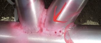
The most commonly used method is the capillary method. To use it, you must have special liquids called penetrants or indicators. These liquids have the ability to penetrate cracks of any size, even the smallest ones. Penetrants are brightly colored, so the presence of cracks becomes noticeable upon visual observation.
The application of indicators is carried out after cleaning the surfaces and drying them. The liquid is applied by wetting or spraying. If the product is small in size, it can be immersed in a container with penetrant. With the vacuum method, the liquid is drawn into the void, and with the compression method, it is forced inside by air pressure. The ultrasonic method consists of filling voids with indicators with ultrasound, and the deformation method drives the penetrating liquid with vibrations of the sound wave.
Magnetic flaw detection
This method can only be used for ferromagnetic compounds. With its help, cracks located inside and inclusions of foreign bodies are identified. To create a magnetic field, you need a device called a flaw detector. It can be used to detect microscopic cracks.
There are several testing methods using magnetic flaw detection:
- Magnetic particle . Ferrimagnetic powder is used, usually consisting of iron particles. It can be dry, or presented in the form of an aqueous emulsion or suspension. When the powder moves uniformly over the surface, it encounters a defect and forms an aggregation. Its size and shape correspond to the parameters of the defect.
- Magnetographic . Surface examination is carried out in conjunction with a magnetic carrier tape. Recording of information from the tape is carried out by special flaw detector devices.
Induction method
Control occurs using induction coils. They are connected to registrars. During the movement of the induction coil, when it meets the location of the defect, the magnetic flux changes and an electromotive force appears. A special device registers the induced current.
Ultrasonic method
Ultrasound, encountering a defective area, changes its direction, which is recorded by a special device. The ultrasound method has several varieties. The method allows you to identify a large number of different defects. It can control all main types of welded joints. The method is safe and can be used for field work.
Radiation method
Allows you to detect pores, areas of lack of penetration, foreign inclusions, cracks. Illumination is carried out with x-rays and gamma rays. The passage of the rays is recorded by a special device. Defects are identified by studying the resulting x-ray image.
Calculation of standards
Regulatory documents define existing types of welding, types of welds and joints and their calculations. First of all, SNiP refers to such a document. It contains rules and regulations that must be followed when carrying out the welding process. SNiP specifies the requirements for the following standards:
- time;
- workings;
- electricity consumption;
- components.
The concept of time consumption includes not only the time spent on the production process itself, but also the auxiliary time necessary for delivering product parts, equipment, tools, and gas cylinders to the welding site.
The time required for the welder to change into a protective suit is taken into account, as well as the time for breaks for rest and lunch. This also includes time for preparatory work before welding and cleaning up after welding.
Additional time is given to set the necessary parameters on the equipment, check its performance, ignite the arc, and apply flux. When making calculations, the qualifications of the performer and his experience are taken into account, which affect the speed of all operations. Tables and formulas are used to calculate time.
Performance standards refer to work that must be completed within a certain time. The unit of measurement can be the value of meters of weld made in one hour, or the number of connections made during this time.
Electricity consumption is an important planning component. The unit of measurement is kilowatt-hours. In addition to the electricity required to operate the equipment, the costs of lighting the welder’s workplace are taken into account.
Necessary expenses include the cost of components. These include tools and accessories, including those necessary for preparatory work. The cost of components includes the cost of purchasing electrodes, flux, and gas.
The standard cost components include wear and tear of equipment and individual components such as roller guides. To avoid different interpretations, all regulatory documents provide a clear definition of what types of welded joints there are and what types of welds there are.
Welding methods
The most common method is manual arc welding. It is applicable to almost all types of weld joints. When the electrode comes into contact with the base metal, an electric arc is formed, which must be maintained during the entire welding process.
How long a weld will withstand depends, in particular, on the correctly selected electrode. There is a wide variety of electrodes of different diameters and coatings available on the market. For critical structures, you should purchase a more expensive, but reliable tool. The types of seams made by arc welding have practically no restrictions. Depending on the electrodes, products from various metals, including high-alloy steel, can be welded in this way. The most common use of arc welding is when connecting products made of structural steel of small thickness.
There are different types of electrode coatings, each of which solves its own problem. Electrodes with basic and rutile coatings are widely used. Cellulose coating is used in DC welding. The advantage of acid coating is easy ignition and minimized splashing of hot metal.
The choice of electrode diameter depends on the thickness of the parts to be welded.
One of the important circumstances when arc welding is the correct choice of current, as well as setting the required distance between the end of the electrode and the metal surface.
Progressive methods include producing welding seams using a semi-automatic machine. The productivity of work using this method is high. Power sources for semi-automatic machines are inverters or rectifiers. The cost of inverters is higher, but their use is more preferable.
Instead of electrodes, semi-automatic welding uses wire of the required diameter. It is supplied automatically using a special device to the work site. In addition to the wire, gas and coolant are supplied through the welding hose.
The wire is wound onto spools of various diameters. The wire tension can be adjusted manually. The wire diameter is selected depending on the thickness of the parts. Deformations of the seam with this method are insignificant, and the welding seams themselves are of high quality. This method is convenient to use for all main types of welded joints.
Scope of application (where used)
Butt welding is an effective technical solution, but it requires the use of highly specialized equipment, which is expensive and can process a limited number of parts.
It is advisable to use it for the following purposes:
- production of plastic and metal structures from rolled products;
- installation of pipelines of any diameter (including the common diameter of 1420 mm);
- construction of buildings and engineering structures (work with reinforcement);
- mechanical engineering and metallurgy (for connecting wires and sheets);
- tool production (metal-cutting tools are created precisely in this way);
- construction and modernization of railways (jointless rails are more modern technology);
- transport and automotive industry (for the manufacture of parts of complex shapes, the implementation of which is difficult with other methods).
At home, there is no need for such technologies - it would be optimal to manually weld the butt seam using more affordable equipment.
When connecting workpieces (or parts of workpieces to each other) using filler material, the method helps to qualitatively produce shells, cylinders, tanks and other reservoirs, shaped (closed) profiles and structures.
State standard requirements
The FNP regulatory standard defines the basic requirements for welding work. It explains what types of welds there are and describes the requirements for each of them. The document contains a rationale for exactly what requirements different types of welded joints and types of seams must meet.
The regulatory documents also explain the designations that all welded joints and types of welding have. All performers need to understand them. Compliance with these requirements guarantees that the seams of welded joints will be strong and reliable.
