Content
- Features of choosing a non-destructive testing method
- Visual and measuring control of welding by external inspection
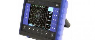
- Ultrasonic flaw detection of welds
- Magnetic flaw detection of welded joints
- Radiographic testing with X-rays and gamma rays
- X-ray control
- Gamma radiation control
- Video: non-destructive testing methods
Non-destructive methods for testing welded joints include external inspection and various types of flaw detection. Non-destructive testing is based on obtaining information about the materials being tested using electromagnetic and acoustic fields, as well as from various substances penetrating into the metal of the product.
To identify internal weld defects, X-ray flaw detection, gamma radiation flaw detection, ultrasonic flaw detection, magnetic flaw detection methods (for example, magnetic particle flaw detection), weld permeability testing (including the capillary flaw detection method), and vacuum flaw detection are widely used.
Requirements for welds
Any welds in the pipeline must not have cracks, craters, burns or other defects of poor quality welding. Undercuts with a depth of more than 0.5 mm will also be very critical. This requirement is especially important for pipelines that operate under pressure from 10 MPa.
The quality of welded joints of different thicknesses of metals is carried out using our own method. For example, when the steel thickness is 16 mm or more, the radiographic method is used. And connections from steels ХМ, С and ХГ are made using the ultrasonic method, during which final flaw detection is carried out.
It is important to follow the sequence of quality control of welded joints. For example, before performing radiography or applying the same ultrasonic flaw detection, it is necessary to use a magnetic particle or color method. This requirement applies to areas near the seam at a distance of 20 mm.
Features of choosing a non-destructive testing method
The choice of the optimal non-destructive testing method depends on the following factors:
1. On the physical properties of the metal being tested 2. On the thickness of the welded joint 3. On the type of welded joint and its thickness 4. On the condition of the joint surface 5. On the manufacturing features of the welded structure 6. On the technical and economic indicators of the testing method and other factors.
A characteristic feature of most non-destructive testing methods is that defects are detected only indirectly, as a result of the analysis of certain physical properties of the welded joint, which do not affect the performance of the product.
For example, during radiation flaw detection, defects of the “continuity” type are determined by the intensity of ionizing radiation passing through the seam. The results of such control methods are often difficult to decipher, so they must be carried out by qualified personnel.
Since among the existing control methods there is no universal one that would guarantee the detection of all defects, it is important, first of all, to detect unacceptable defects. Each method has its own advantages and disadvantages. In most cases, several methods are used. This approach allows you to detect a defect with a high degree of probability. Next, we will consider each of the control methods separately.
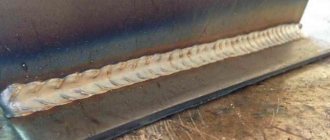
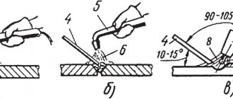
Visual and measuring control of welding by external inspection
External inspection can only reveal external defects in the weld. Inspection can be done both with the naked eye and with the help of a magnifying glass with multiple magnification. The dimensions of the welds are checked using templates and measuring tools.
External inspection is usually applied to all welds, regardless of the degree of structural responsibility and whether other inspection methods are used. More details about this control method are described on the page: “Control of welds by external inspection and measurement.”
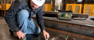
Ultrasonic flaw detection of welds
The ultrasonic flaw detection method is based on the property of ultrasonic waves to pass through a large thickness of metal and be reflected from accumulations of slag, non-metallic inclusions and other defects in the weld.
Ultrasonic flaw detectors operate on the following principle: a plate of quartz or Rochelle salt is exposed to a high-frequency electric field. Under the influence of the field, the plate emits ultrasonic waves, which are directed to the welded joint.
At the boundary between the homogeneous metal and the defect, ultrasonic vibrations are reflected, and the reflected wave is perceived by the second plate. Under the influence of the reflected wave, a variable potential difference is formed on this plate, the magnitude of which depends on the intensity of the reflected wave.
Next, the electrical vibrations emanating from the plate are amplified and transmitted to an oscilloscope. On the oscilloscope screen, the pulses of the wave directed to the weld and the wave reflected from the defect in the weld are simultaneously displayed. The location and nature of the weld defect is determined by the location of these pulses.
The ultrasonic flaw detection method allows you to identify all known defects in welded joints. This non-destructive testing method is described in more detail in the article: “Ultrasonic testing of welds. Ultrasonic flaw detection".
Magnetic flaw detection of welded joints
The essence of the magnetic flaw detection method is to excite a non-uniform magnetic field passing through the welded joint with the formation of scattered magnetic fluxes in areas containing welded defects.
There are several methods of magnetic testing: magnetic particle flaw detection, magnetographic testing and induction testing. Magnetic particle flaw detection is the simplest of them, but the reliability of control of this method is lower than that of others.
In magnetic particle flaw detection, the joint being tested is magnetized, magnetic powder (iron scale or fine iron filings) or a suspension is applied to its surface, and a magnetic field is passed through the joint. Magnetic powder or suspension, under the influence of a magnetic field, will be distributed evenly. But in places where defects are located, accumulations of magnetic powder (suspension) will be observed.
During magnetic testing, the magnetic field passed through the welded joint is recorded on magnetic film. To do this, a magnetic film is applied to the connection while a magnetic field passes through it. Next, using magnetic flaw detectors, I read the recorded information from the film and convert it into sound or into an image on the monitor of the flaw detector. In addition to these methods, there is an induction method of magnetic flaw detection.
More detailed information about these control methods can be found on the page: “Magnetic methods for testing welds. Magnetic flaw detection of welding.”
Magnetic control
This is a set of NDT methods needed to detect defects in ferromagnetic metals and alloys. Magnetic flaw detection allows you to detect inclusions of non-metallic origin, cracks, hairlines, flakes. Defects can be found if they are on the surface of the product or if they lie at a shallow depth (2-3 mm).
The essence of magnetic methods is to study magnetic stray fields near magnetized ferromagnetic materials. The location of the defect is indicated by redistributed magnetic fluxes and generated magnetic stray fields.
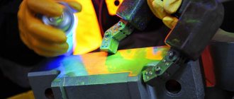
Radiographic testing of welded joints. X-ray and gamma ray control
X-ray control
X-rays propagate differently in different materials. For example, such rays will pass differently through a homogeneous metal, through slag inclusions, or through a void in the metal. The X-ray flaw detection method is based on this property of X-ray radiation, the diagram of which is shown in the figure.
To control the weld, a radiation source is installed on one side and a detector on the opposite side. X-rays, passing through the seam from the source, irradiate the detector (photographic film or photographic paper), which displays a complete picture of the passage of the rays through the metal. The presence of darkened areas on the film indicates that the intensity of the rays in these areas was high, therefore, there are defects in these areas of the welded joint. For more complete information about this non-destructive testing method, see the page: “Radiographic method of testing welded joints Part 1 X-ray testing.”
Gamma radiation control
Gamma ray inspection, like X-ray inspection, is based on the ability of gamma rays to pass differently through metal, non-metallic inclusions, and voids in metal.
The gamma control scheme is as follows: from an ampoule containing radioactive isotopes, a stream of gamma rays is directed to the controlled connection. On the reverse side of the connection there is a cassette with film or photographic paper, which displays a complete picture of the passage of rays through the metal. In places where defects are detected, darkened areas will appear on the film. In order to regulate the flow of radioactive radiation, the ampoule is placed in a lead container with a small hole through which the flow of gamma rays exits.
Radiation flaw detection has advantages over x-ray scanning. For example, gamma rays have greater penetrating power, which allows them to be used when inspecting large metal thicknesses, more than 300 mm thick. In addition, gamma radiation control is more cost-effective because has a lower cost. But, it also has its drawbacks. For example, radiation poses a great danger to human health. More details about this method of welding control are described on the page: “Radiographic method of testing welded joints Part 2 Radiation testing by gamma radiation.”
How important is quality control?
Damage to pipelines may be related to their appearance or their technical characteristics. Any defects reduce the reliability of the entire system. Damage may occur when creating seams or during metallurgical work.
The condition of the pipes of water supply and sewerage systems must be checked in several stages. Correctly following the sequence will ensure safe operation.
Non-destructive testing of pipeline welded joints is divided into the following stages:
- production supervision;
- workers checking the appearance of welds;
- control of corrosion, tightness, insulation;
- mechanical control tests.
Verification must be multi-level. For example, to check the insulation of a pipeline, the first non-destructive testing is carried out during welding work. Next, the integrity and thickness of the insulating coating are monitored. Devices required at all stages:
- Thickness gauges for pipeline coating.
- Electric spark flaw detectors.
- Adhesion meters.
Adhesion meter
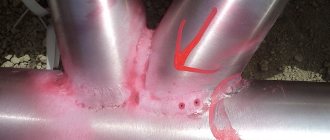
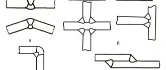
Welded seams in structures require especially careful inspection. If they have defects, they will lead to a violation of the tightness of the system. Types of defects can be distinguished by type:
- external or subsurface damage located at close range;
- internal destruction, deep, which cannot be seen with the naked eye.
Both varieties are divided into:
- on cracks;
- surges;
- undercuts;
- craters.
Cracks are considered the most dangerous damage to pipelines. They instantly destroy welded joints. Defects may appear during welding or after.
When molten metals build up one above the other, and a single seam is not formed, leaky sagging results.
The areas where welds transition to metal are called undercuts. The defect often appears at joints under heavy load. The tension in these places is so high that the pipeline is bursting.
When the welding arc breaks, craters appear, which are small depressions. They reduce the cross-sectional area, which reduces strength. Dirt accumulates in the craters, which also destroys the pipeline.
Internal defects
Internal defects include:
- lack of penetration;
- porosity;
- particle accumulations;
- through cracks;
- burns.
Lack of fusion is a small area of unmelted metal. There is no seam in this place or it is smaller in area. This causes increased stress and, under load, pipeline ruptures.
When liquid alloy leaks through a hole in the joint, a burn occurs. In this place you can observe a leak, which reduces the tightness. This requires urgent repair, as do through-and-through cracks.
Non-destructive testing can be called methods that improve quality and preserve the integrity of the structure. It can be organized both during system installation and after.